AETEK VR-486 Series User manual

Installation Guide
VR-486 / VW-486 / VR-806 Series
Vari-Angle Illuminator
Rev. 1.0
2
Revision History:
* Rev. 1.1: Initial Release
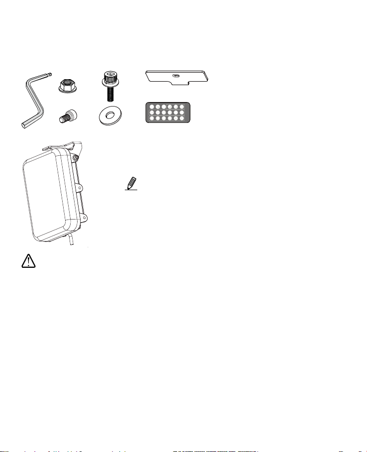
Package Contents
X3
X1
X2
X2
• The wall-mount , laser alignment kit , remote controller , and
other accessory are separately purchased.
• The screws and anchors for securing the illuminator to wall are
user-supplied. Apply M6 anchors or screws.
NOTE:
The 1/4" screws and washers are used to secure the illuminator
to an external camera housing.
• Please avoid eye exposure or apply appropriate protection, such as wearing a pair of Infrared
protection glasses, when working with the product. Always use camera live view to oberve IR
lighting effects.
WARNING:
• The luminaire should be positioned so that prolonged staring into the luminaire at a distance
closer than 2.5 m is not expected.
• Theexternalexiblecableorcordofthisluminairecannotbereplaced;ifthecordisdamaged,
the luminaire shall be destroyed.
• Thelightsourceofthisluminaireisnotreplaceable;whenthelightsourcereachesitsendoflife
the whole luminaire shall be replaced.
• Please make sure Reinforce/Double insulation shall be maintained between LV supply and control
circuits after installation.
• ThisoodlightshallbeusedwithaIEC/EN61347-2-13approvedLEDdriverwithSELVoutput
equaltoratedvoltageoftheluminaire,andoutputpowerofLEDdriversshallbeatleastequalto
rated power of the luminaire.
• Terminalblockisnotincluded.Installationmayrequireadvicefromaqualiedpersonnel.
Dimming
LED
Status
LED
On/Off
T
W
Zoom
50%
20%
10%
100%
75%
50%
25%
VR-486 series only
VR-806 series only

3
• Do not install the product with unstable brackets, or installed on fragile mount surfces.
• This product shall be used in compliance with local laws and regulation.
• Please avoid using chemical oraerosolcleaninguidstocleantheproduct. Use a clean cloth
slightly moistened with water.
• Thisproductcontainsnopartsrepairablebytheusers.ContactVR-486forservices.
• Power off the Illuminator as soon as smoke or unusual odors are detected.
• Do not place the Illuminator on unsteady surfaces.
• Replacing or failing to properly install the waterproof components, e.g., cables or cable glands,
willvoidourIP67warranty.
• Refer to your datasheet for the operating temperature.
• Do not touch the Illuminator during a lightning storm.
IMPORTANT:
ClassIIIluminaires
Do not stare at the operating light source.
This marking indicates that this product should not be disposed with other household
wastesthroughouttheEU.Topreventpossible harm totheenvironmentorhumanhealth
from uncontrolled waste disposal, recycle it responsibly to promote the sustainable reuse
of material resources. To return your used device, please use the return and collection
systems or contact the retailer where the product was purchased. They can take this
product for environmental safe recycling.
RISK GROUP 3
WARNING IR emitted from this product,
Do not look at operating lamp.
IRilluminatorsRISKGRORP3/WARNINGIR emitted from this product. /Avoideyeexposure.Use
appropriate shielding or eye protection. Do not look at operating lamp.

4
69.4mm(2.73")
90mm(3.54")
50mm(1.97")
236mm(9.3")
160mm(6.3")
220mm(8.66")
49mm(1.93")
73mm(2.87")
93.4mm(3.68")
27.4mm(1.08")
117.4mm(4.62")
69.4mm(2.73")
43mm(1.7")
Standard Small U bracket
50
R60
15 ~
25
9.85
9.5
M6x1
134
23
6.2
24
36
90
5.9
n6.2
3
31
18.5
46
54
48
24
20
3
Mechanical Drawings
Standard Small U bracket

5
Hardware Overview
I
Reserved mounting holes for
external camera housing
Ubracket
Optionalmountingpointsfor
Ubracket
Light sensor
Combocable
Dehumidier
membrane
Reserved
Mounting holes
Unit Weight:2.1KG.
Max. Project Area:34684.7mm2.
160mm(6.3")
220mm(8.7")
6
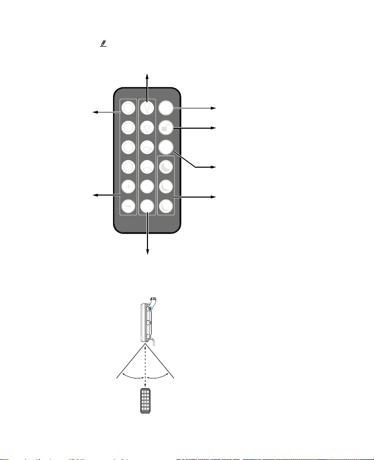
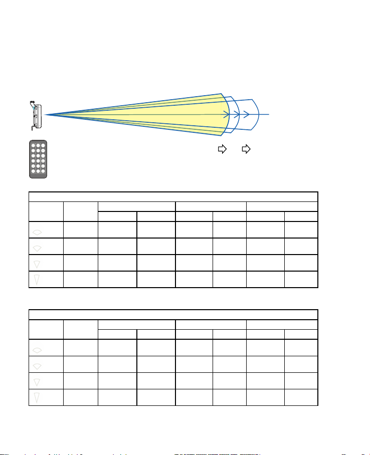
Beam angle selectors
Only function in VR806 series
These buttons provide quadruple proportions of adjustable
angles from the narrowest, 33%, 66%, to the widest. These angles vary
with different models. When a beam angle is selected, you can use
the fine-tune buttons below to tune for a desired effect.
Angle fine-tune
After a preset beam angle is selected, use these buttons
to fine-tune. T stands for tele, W for wide.
Dimming
LED
Status
LED
On/Off
T
W
Zoom
50%
20%
10%
100%
75%
50%
25%
LED on/off
Unlock
Remote control is disabled by default.
Unlock the remote control by pressing this button for
2 seconds. The control is automatically locked after
being idle for 5 mins.
LED status
The button toggles the LED indicators on or off.
The LEDs are only visible on the non-IR illuminators,
such as w5.
Light sensor sensitivity
These buttons provide direct access to the pre-
defined light sensor thresholds that turn the LEDs on.
LED dimming
These are four pre-defined lighting
strength levels.
LED dimming fine-tune
These buttons can be used to
change the lighting strength levels
from 100% to 20%.
Using the Remote Controller
Dimming
LED
Status
LED
On/Off
T
W
Zoom
50%
20%
10%
100%
75%
50%
25%
15m
Effective range
45° 45°
Effective range for remote controller

7
VR-486 series
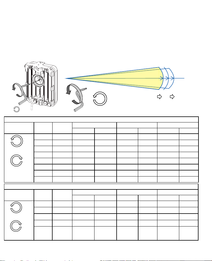
Beam angle adjust:
Youmustrstsurveytheinstallationsiteanddeterminetheilluminationdistance.
Useacoinoratbladescrewdrivertoopenthewaterproofcoveratthebackoftheilluminator.
35-Kg-cm
Beam angle
selector
Angle wider
Angle narrower
Longer distance
Shorter distance
Usethe4mmsideoftheallenwrenchtoturnthebeamangletoanestimatedilluminationdistance,e.g.,
200meters.Seethetablesonthenextpageforhowtodoit.
You may forget your current beam angle
conguration. In this case, turn many full circles
clockwise until the rotation resistance is felt (returns
to the widest angle, reaches its mechanical stops),
and then turn the selector counter-clockwise
accordingtotheanglelistedonthetables.Eachfull
circle corresponds to a preset beam angle.
Tips:
Installation
II
8
VR-486-1040
Rotate
direction
Full circle Beam angle Single mount Double mount Triple mount
Distance(m) Width(m) Distance(m) Width(m) Distance(m) Width(m)
0 40° 100 72.8 141.4 102.9 173.2 126.1
1 36° 107 69.5 151.3 98.3 185.3 120.4
2 30° 127 68.1 179.6 96.3 220.0 117.9
3 27° 137 65.8 193.7 93.0 237.3 113.9
4 24° 150 63.8 212.1 90.2 259.8 110.4
5 16° 206 57.9 291.3 81.9 356.8 100.3
6 15° 215 56.6 304.1 80.1 372.4 98.1
7 10° 250 43.7 353.6 61.9 433.0 75.8
Counter-clockwide
Narrower
Clockwide
Wider
VR-486-2040
Rotate
direction
Full circle Beam angle Single mount Double mount Triple mount
Distance(m) Width(m) Distance(m) Width(m) Distance(m) Width(m)
0 40° 120 87.4 169.7 123.5 207.8 151.3
1 36° 125 81.2 176.8 114.9 216.5 140.7
2 29° 150 77.6 212.1 109.7 259.8 134.4
3 27° 158 75.9 223.4 107.3 273.7 131.4
4 20° 200 70.5 282.8 99.7 346.4 122.2
Counter-clockwide
Narrower
Clockwide
Wider
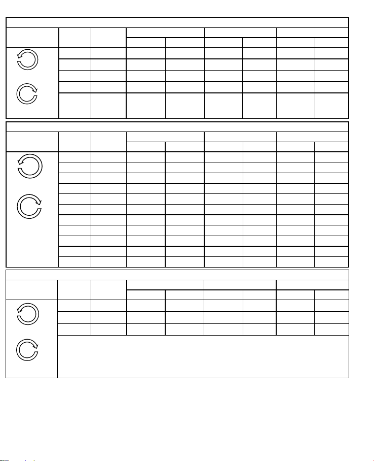
The factory default for the beam angle selector is always at the Widest angle.Whenyouturnthe
selector many rounds to its widest or the narrowest position, a rotation resistance can be felt. That
means the mechanical stop is reached, and you should not use more force.
RefertothetablesbelowforthecongurableIRlightbeam angles and the number of full circles
neededtochangetothepreferredbeamangles.Eachfullcirclecorrespondstoapresetbeamangle.
Forexample,ifyouneedtochangeVR-486-1040'sbeamangleto30°(127m),turnthebeamangle
selector Counter-clockwise 2 full circles.Ifyouareatthenarrowestangle(10°)andprefertoturnto
24°,turn3fullcirclesclockwise.Whendone,installthewaterproofcover.
X2
Width
Distance
Angle
X2 30°36°
40°

9
VR-486-4080
Rotate
direction
Full circle Beam angle Single mount Double mount Triple mount
Distance(m) Width(m) Distance(m) Width(m) Distance(m) Width(m)
0 80° 60 100.7 84.9 142.4 103.9 174.4
1 77° 62 98.6 87.7 139.5 107.4 170.8
2 74° 64 96.5 90.5 136.4 110.9 167.1
3 66° 67 87.0 94.8 123.1 116.0 150.7
4 63° 69 84.6 97.6 119.6 119.5 146.5
5 60° 71 82.0 100.4 115.9 123.0 142.0
6 55° 75 78.1 106.1 110.4 129.9 135.2
7 52° 79 77.1 111.7 109.0 136.8 133.5
8 50° 82 76.5 116.0 108.2 142.0 132.5
9 45° 86 71.2 121.6 100.8 149.0 123.4
10 40° 90 65.5 127.3 92.7 155.9 113.5
VR-486-90120
Rotate
direction
Full circle Beam angle Single mount Double mount Triple mount
Distance(m) Width(m) Distance(m) Width(m) Distance(m) Width(m)
0 120° 45 155.9 63.6 220.5 77.9 270.0
1 105° 50 130.3 70.7 184.3 86.6 225.7
2 90° 55 110.0 77.8 155.6 95.3 190.5
Counter-clockwide
Narrower
Clockwide
Wider
Counter-clockwide
Narrower
Clockwide
Wider
VR-486-180
Rotate
direction
Full circle Beam angle Single mount Double mount Triple mount
Distance(m) Distance(m) Distance(m)
Fixed angle N/A 180° 40 56.6 69.3
VW-486-1040
Rotate
direction
Full circle Beam angle Single mount Double mount Triple mount
Distance(m) Width(m) Distance(m) Width(m) Distance(m) Width(m)
0 40° 100 72.8 141.4 102.9 173.2 126.1
1 36° 107 69.5 151.3 98.3 185.3 120.4
2 30° 127 68.1 179.6 96.3 220.0 117.9
3 27° 137 65.8 193.7 93.0 237.3 113.9
4 24° 150 63.8 212.1 90.2 259.8 110.4
5 16° 206 57.9 291.3 81.9 356.8 100.3
6 15° 215 56.6 304.1 80.1 372.4 98.1
7 10° 250 43.7 353.6 61.9 433.0 75.8
Counter-clockwide
Narrower
Clockwide
Wider
10
VW-486-2040
Rotate
direction
Full circle Beam angle Single mount Double mount Triple mount
Distance(m) Width(m) Distance(m) Width(m) Distance(m) Width(m)
0 40° 120 87.4 169.7 123.5 207.8 151.3
1 36° 125 81.2 176.8 114.9 216.5 140.7
2 29° 150 77.6 212.1 109.7 259.8 134.4
3 27° 158 75.9 223.4 107.3 273.7 131.4
4 20° 200 70.5 282.8 99.7 346.4 122.2
Counter-clockwide
Narrower
Clockwide
Wider
VW-486-4080
Rotate
direction
Full circle Beam angle Single mount Double mount Triple mount
Distance(m) Width(m) Distance(m) Width(m) Distance(m) Width(m)
0 80° 60 100.7 84.9 142.4 103.9 174.4
1 77° 62 98.6 87.7 139.5 107.4 170.8
2 74° 64 96.5 90.5 136.4 110.9 167.1
3 66° 67 87.0 94.8 123.1 116.0 150.7
4 63° 69 84.6 97.6 119.6 119.5 146.5
5 60° 71 82.0 100.4 115.9 123.0 142.0
6 55° 75 78.1 106.1 110.4 129.9 135.2
7 52° 79 77.1 111.7 109.0 136.8 133.5
8 50° 82 76.5 116.0 108.2 142.0 132.5
9 45° 86 71.2 121.6 100.8 149.0 123.4
10 40° 90 65.5 127.3 92.7 155.9 113.5
VW-486-90120
Rotate
direction
Full circle Beam angle Single mount Double mount Triple mount
Distance(m) Width(m) Distance(m) Width(m) Distance(m) Width(m)
0 120° 45 155.9 63.6 220.5 77.9 270.0
1 105° 50 130.3 70.7 184.3 86.6 225.7
2 90° 55 110.0 77.8 155.6 95.3 190.5
Counter-clockwide
Narrower
Clockwide
Wider
Counter-clockwide
Narrower
Clockwide
Wider
11
Usetheremotecontrollertoadjustthebeamangle.
VR-806-1040
Button Beam angle Single mount Double mount Triple mount
Distance(m) Width(m) Distance(m) Width(m) Distance(m) Width(m)
40° 140 101.9 198.0 144.1 242.5 176.5
30° 178 95.4 251.7 134.9 308.3 165.2
20° 250 88.1 353.5 124.7 433.0 152.6
10° 350 61.2 495.0 86.6 606.2 106.1
The factory default for the beam angle selector is always at the Widest angle.
RefertothetablesbelowforthecongurableIRlightbeam anglesandthedenitionsoftheremote
controllerbuttons.Eachbuttonchangestoapresetbeamangle.
Width
Distance
Angle
27°33°
40°
Dimming
LED
Status
LED
On/Off
T
W
Zoom
50%
20%
10%
100%
75%
50%
25%
Example:
VR-806-2040
Button Beam angle Single mount Double mount Triple mount
Distance(m) Width(m) Distance(m) Width(m) Distance(m) Width(m)
40° 170 123.7 240.4 175.0 294.4 214.3
33° 190 112.6 268.7 159.2 329.1 195.0
27° 221 106.1 312.5 150.1 382.8 183.8
20° 280 98.7 396.0 139.6 485.0 171.0
VR-806 series

12
Name Color Gauge Description
V+ Red (20AWG) Power input
24VDC±10%
24VAC±10%(50/60Hz)
V- Black (20AWG)
DI+ Green (26AWG) LEDON/OFFcontrol
* Dry contact
Logiclevel1(Open)=LEDoff
Logiclevel0(ClosetoGND)=LEDon
*Wetcontact
Logiclevel1:4V~40V=LEDoff
Logiclevel0:0.8VMAX=LEDon
DI- Yellow (26AWG) Ground
DO+ Purple (26AWG) Light sensor status output
1.Open=Day
2.Short=Night(300luxforIRON)
DO- Blue (26AWG) Ground
RS485+ Orange (26AWG) RS485interfacecontrol
RS485- Brown (26AWG)
Cable Pinouts
13
External
power source
Relay
NO NC
+3.3V+3.3V
R
R
R
GND GND GND
Switch
+3.3V
R
GND
Fuse/50mA
GND
Camera DI pins
DI+
DI-
DO+
DO-
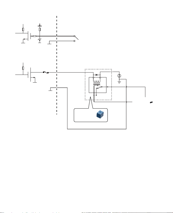
Coordination with Cameras via the DI and DO Pins
IR LED ON/OFF control (Green & Yellow wires)
This mode means that illuminatorOn/Offcontrolistriggeredbycameraorotheralarmsystem.Users
can decide using the appropriate dry/wet contacts depending on wiring condition.
DI+:Green=TTL+voltage
DI-:Yellow=TTL–voltage(GND)
* Dry contact
Logiclevel1(Open)=LEDoff
Logiclevel0(ClosetoGND)=LEDon
*Wetcontact
Logic level 1: 4V~40V=LEDoff
Logiclevel0:0.8VMAX=LEDon

14
Light sensor status output (Purple & Blue wires)
ThismodemeansthatcameraDay/Nightmodeswitchingiscoordinatedwithandistriggeredbythe
illuminator'slightsensorviatheDO(Digitaloutput)connection(connectedtothecamera'sDIpins).
UserscancongurethecameracongurationtocontrolthecorrespondingilluminatorOn/Offstatus.
DO+:Purple=Opendrainoutput,45VMax.(currentmustbeunder100mA)
DO-:Bule=GND
Light sensor status output
1.Open=Day
2.Short=Night(lowerthan300luxforIRtoturnON)
Stand-alone illuminator mode
Thismodemeansthattheilluminator'sOn/Offcontrolistriggeredbyitslightsensor,inthecase,the
default wiring is connecting the green wire with purple wire.
Somecamerashaverelatedsettingsthatneedtheinter-connectionwiththeilluminator.Forexample,
somecamerascomewithanIRcutlterthatneedtobeturnedoffwhenenteringnightmode;or,
automaticallyturnontheadjacentilluminatorwhenenteringnightmode.

15
SwivelPositionsandDirections
105 mm
502.8 mm
135.5 mm
158.5 mm
170 mm
400 mm
77.4 mm
USABLE
AREA
255 mm
USABLE AREA
400
170 502.8
Mounting Conguration & Dimensions
III
16
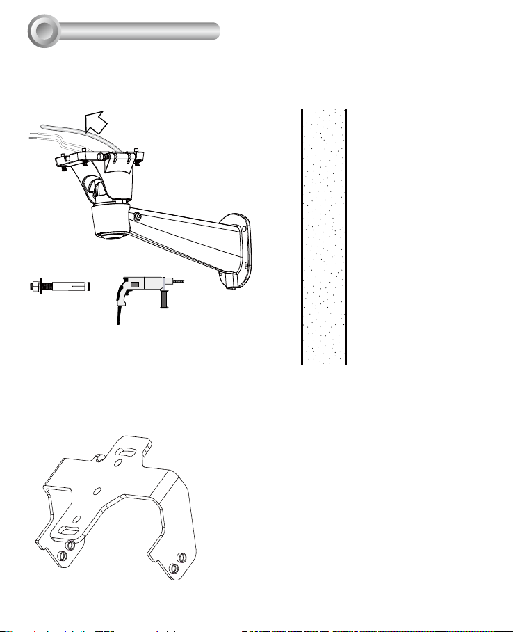
1. Install the wall-mount bracket to a preferred location at your installation site. Drill
mounting holes and a cable routing hole (if preferred) on a wall. Install the bracket.
Prepareandroutethewiring,Ethernetand24Vpowersource.
2.
Install the IR illuminator to the bottom of the housing. Attach the included grip stricker
to the U bracket.
IV Installation
17
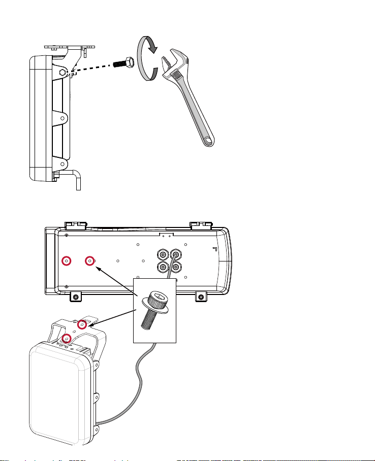
3.
Secure the U bracket to the IR illuminator using the included hex screws.
4.Flipthehousingoverandplaceitonaclean,stablesurface.SecuretheIRilluminator
to the bottom of the housing using the included wrench and a hex socket screw.
18
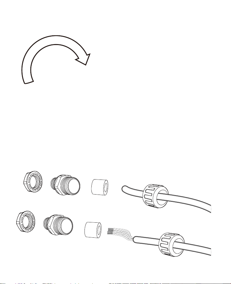
6.Preparepowerwires,agroundwire,andaCAT5eEthernetcable.Passthemthrough
the M16 waterproof connectors under the housing.
Ethernet cable Ø4 ~ 6.5mm
Power wires & DI/DO wires,
a combo cable from IR illuminator
(if applied)
5.YoucanturntheIRilluminatorsothatitsatsideisparallelwiththehousing,andthat
you can turn the assembly over and work on the inside of the housing. Put a foam pad
below before you work on the wiring to avoid scratching the surface.
19
7.Whendone,tightenupandinstallthewaterproofconnectors.
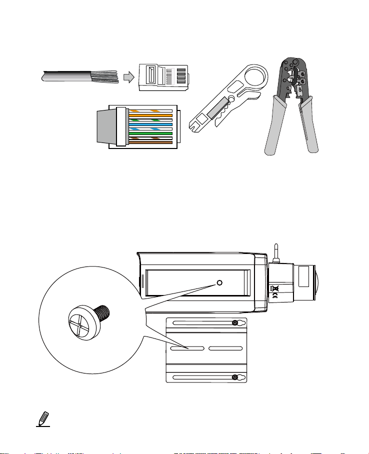
8.Assemblethecameracomponents,e.g.,theCSringandlensmodule.Securethe
mounting plate to the bottom of the camera (the label side) using the included screw.
There is a plastic mount pad in the package. You do not need the mounting pad
usingtheAETEKcamera.
o
O
g
B
b
G
br
BR
1
2
3
4
5
6
7
8
o: white/orange stripe
O: orange solid
g: white/green stripe
B: blue solid
b: white/blue stripe
G: green solid
br: white/brown stripe
BR: brown solid
You may need to remove the RJ45 connector, and use a crimping tool to connect the
EthernetwirestoanRJ45connectorinsidetheenclosure.UseanEthernetcableofthe
width of 4 ~ 6.5mm.

20
This page is intentionally left blank.
This manual suits for next models
13
Table of contents


