AEV Synapse User manual
AEV SYNAPSE
AEV Broadcast
Web site
AEV
Broadcast On Air Console
Broadcast On Air ConsoleBroadcast On Air Console
Broadcast On Air Console
AEV SYNAPSE
- ON AIR CONSOLE
AEV Broadcast
Srl – via della Tecnica 33 –
40050 Argelato (BO) Italy
Web site
www aev eu e-mail info@aev eu
AEV
SYNAPSE
SYNAPSESYNAPSE
SYNAPSE
Broadcast On Air Console
Broadcast On Air ConsoleBroadcast On Air Console
Broadcast On Air Console
40050 Argelato (BO) Italy
1
Broadcast On Air Console
Broadcast On Air ConsoleBroadcast On Air Console
Broadcast On Air Console

AEV SYNAPSE
AEV Broadcast
Web site
Guarantee
The equipment is warranted for a period of 2 years from the date of invoice
warranty does not cover faults provoked by carelessness, natural causes and parts subject to
wear In addition, the cost of shipment is not covered The arranty will be voided if the
equipment is mishandled
Technical Support
If you requir
e technical support, contact AEV SERVICE giving a clear and concise account of
your specifc problem Quote the serial number of your equipment by referring to the AEV
nameplate attached to the equipment itself as this is the most important piece of informa
to be provided
Telephone: +39 051892963 Fax: +39 051893605
Factory Service and Repairs
If problems arise while the equipment is being installed, consult this manual and check that
the installation is being carried out properly If the problems still cannot be solved, call the AEV
SERVICE Department for further information If the problem is
call will probably sufice If, on the other hand, the equipment is to be shipped to AEV for
service or repairs, the AEV SERVICE Dept will accept it only if the RMA return authorisation
number has been provided This number
recommend providing a detailed description of the fault which has occurred, the type of service
needed and (if required) the name of the employee at the AEV SERVICE Dept you have
spoken to No repairs wi
ll be made if the cost of shipment is charged to AEV In this case, we
will not accept the delivery
Shipping Instruction
When shipping the equipment to AEV, use the original package in order to be certain that it will
be fully protected during ndling I
If you ship the equipment in a different packing container, take care to provide a double
package by interposing padding material between the two containers in order to fully protect
the equipment dur
ing shipment. The package should be marked
IMPORTANT:
Carefully read this paragraph as it contains important instructions concerning
operator safety and directions regarding the installation, operation and maintenance of the
equipment
Failure to observe the safety instructions and information given in this manual
infringement of the safety rules and design
equipment
Futurcom srl declines all responsibility
observed
Futurcom srl declines all responsibility
The equipment is to be used by people capable of operating it in a trouble
is assumed that they are aware of the followin
• Keep this manual with the utmost care and close at hand so that it can be consulted
whenever needed
• After unpacking the equipment, check it for condition
• Avoid banging the equipment
• The packing material (plastic bags, polystyrene,
reach of the children, as
these items are potential sources of danger
• Do not use the equipment in places where the temperature is not within the
range, as speciied by the manufacturer
• Before connecting the equipment, make sure the nameplate specifications
mains electricity supply (the nameplate is located on the equipment enclosure)
• Do not remove the sticker from the equipment as it contains important
relevant serial number
AEV SYNAPSE
- ON AIR CONSOLE
AEV Broadcast
Srl – via della Tecnica 33 –
40050 Argelato (BO) Italy
Web site
www aev eu e-mail info@aev eu
The equipment is warranted for a period of 2 years from the date of invoice
warranty does not cover faults provoked by carelessness, natural causes and parts subject to
wear In addition, the cost of shipment is not covered The arranty will be voided if the
e technical support, contact AEV SERVICE giving a clear and concise account of
your specifc problem Quote the serial number of your equipment by referring to the AEV
nameplate attached to the equipment itself as this is the most important piece of informa
Telephone: +39 051892963 Fax: +39 051893605
If problems arise while the equipment is being installed, consult this manual and check that
the installation is being carried out properly If the problems still cannot be solved, call the AEV
SERVICE Department for further information If the problem is
a minor one we can a telephone
call will probably sufice If, on the other hand, the equipment is to be shipped to AEV for
service or repairs, the AEV SERVICE Dept will accept it only if the RMA return authorisation
number has been provided This number
must be included in the shipping documents We also
recommend providing a detailed description of the fault which has occurred, the type of service
needed and (if required) the name of the employee at the AEV SERVICE Dept you have
ll be made if the cost of shipment is charged to AEV In this case, we
When shipping the equipment to AEV, use the original package in order to be certain that it will
be fully protected during ndling I
f you need the original package, call us for a new one
If you ship the equipment in a different packing container, take care to provide a double
package by interposing padding material between the two containers in order to fully protect
ing shipment. The package should be marked
“FRAGILE”
in red.
Carefully read this paragraph as it contains important instructions concerning
operator safety and directions regarding the installation, operation and maintenance of the
Failure to observe the safety instructions and information given in this manual
infringement of the safety rules and design
specifications provided for this piece of
Futurcom srl declines all responsibility
if any one of the safet
y rules given herein is not
Futurcom srl declines all responsibility
if the end-
user resells the product
The equipment is to be used by people capable of operating it in a trouble
-
is assumed that they are aware of the followin
g safety rules.
• Keep this manual with the utmost care and close at hand so that it can be consulted
• After unpacking the equipment, check it for condition
• Avoid banging the equipment
• The packing material (plastic bags, polystyrene,
nails, etc ) must never be left within the
these items are potential sources of danger
• Do not use the equipment in places where the temperature is not within the
range, as speciied by the manufacturer
• Before connecting the equipment, make sure the nameplate specifications
mains electricity supply (the nameplate is located on the equipment enclosure)
• Do not remove the sticker from the equipment as it contains important
specificatio
40050 Argelato (BO) Italy
2
The equipment is warranted for a period of 2 years from the date of invoice
(ex-works) The
warranty does not cover faults provoked by carelessness, natural causes and parts subject to
wear In addition, the cost of shipment is not covered The arranty will be voided if the
e technical support, contact AEV SERVICE giving a clear and concise account of
your specifc problem Quote the serial number of your equipment by referring to the AEV
nameplate attached to the equipment itself as this is the most important piece of informa
tion
If problems arise while the equipment is being installed, consult this manual and check that
the installation is being carried out properly If the problems still cannot be solved, call the AEV
a minor one we can a telephone
call will probably sufice If, on the other hand, the equipment is to be shipped to AEV for
service or repairs, the AEV SERVICE Dept will accept it only if the RMA return authorisation
must be included in the shipping documents We also
recommend providing a detailed description of the fault which has occurred, the type of service
needed and (if required) the name of the employee at the AEV SERVICE Dept you have
ll be made if the cost of shipment is charged to AEV In this case, we
When shipping the equipment to AEV, use the original package in order to be certain that it will
f you need the original package, call us for a new one
If you ship the equipment in a different packing container, take care to provide a double
package by interposing padding material between the two containers in order to fully protect
in red.
Carefully read this paragraph as it contains important instructions concerning
operator safety and directions regarding the installation, operation and maintenance of the
Failure to observe the safety instructions and information given in this manual
constitutes an
specifications provided for this piece of
y rules given herein is not
user resells the product
-
free manner and it
• Keep this manual with the utmost care and close at hand so that it can be consulted
nails, etc ) must never be left within the
• Do not use the equipment in places where the temperature is not within the
recommended
• Before connecting the equipment, make sure the nameplate specifications
correspond to the
mains electricity supply (the nameplate is located on the equipment enclosure)
specificatio
ns and the

AEV Broadcast
Web site
• To join the equipment to the mains supply, use the power cord purchased with the
equipment
• The equipment must be used only for the purpose it was designed for
• Abuse or misuse of the equipment is
The manufacturer declines all responsibility for damage and injury resulting from
use and mishandling
• Certain basic safety rules must be observed when using electrical equipment, in particular:
Never touch the
equipment with wet and/or damp hands or other parts of the body
-
Keep the equipment away from drops of water or sprinkling systems
-
Never use the equipment near high heat sources or explosive material
-
Do not introduce any extraneous matter into the
-
Do not allow children or untrained people to use the equipment
• Before cleaning or servicing the equipment outside, disconnect it from the supply and wait at
least 2 seconds before working on it, as recommended by current safety regulations
• In the event of faults and/or improper operation, turn off the equipment, shut off the
electrical power and call your dealer
• Do not attempt to make repairs and/or adjustments when covers/guards or circuit boards are
to be removed
• Blown fuses insi
de the power supply indicate that there may be a fault in
itself The fuses must be replaced by qualiied and authorised
your nearest dealer
• Call your dealer for any repairs and be certain original spare
Failure to observe this rule may adversely affect the safety level of your equipment
• The equipment is to be connected to the mains supply and provided with
eficient earth conductors
• The electrical wiring must be done in c
“Electrical speciication for domestic buildings”
• When installing, leave a clearance of at least 1 cm around the equipment to
allow air to pass freely
NOTE. This piece of equipment has been manufactured
workmanship. t must be used
long-term
dependable operation.
The installation must be done in order to be able to guarantee an easy access to the cable of
feeding
The device of dis
section of the equipment is the cable of feeding, so it must be unconnected
from the equipment every time it is necessary to do any type of maintenance
AEV SYNAPSE - ON AIR CONSOLE
AEV Broadcast
Srl – via della Tecnica 33 – 40050
Argelato (BO) Italy
Web site
www aev eu e-mail info@aev eu
• To join the equipment to the mains supply, use the power cord purchased with the
• The equipment must be used only for the purpose it was designed for
• Abuse or misuse of the equipment is
extremely dangerous
for people, pets and property
The manufacturer declines all responsibility for damage and injury resulting from
• Certain basic safety rules must be observed when using electrical equipment, in particular:
equipment with wet and/or damp hands or other parts of the body
Keep the equipment away from drops of water or sprinkling systems
Never use the equipment near high heat sources or explosive material
Do not introduce any extraneous matter into the
equipment
Do not allow children or untrained people to use the equipment
• Before cleaning or servicing the equipment outside, disconnect it from the supply and wait at
least 2 seconds before working on it, as recommended by current safety regulations
• In the event of faults and/or improper operation, turn off the equipment, shut off the
electrical power and call your dealer
• Do not attempt to make repairs and/or adjustments when covers/guards or circuit boards are
de the power supply indicate that there may be a fault in
itself The fuses must be replaced by qualiied and authorised
persons It is advisable to call
• Call your dealer for any repairs and be certain original spare
parts are used
Failure to observe this rule may adversely affect the safety level of your equipment
• The equipment is to be connected to the mains supply and provided with
• The electrical wiring must be done in c
ompliance with current electrical codes
“Electrical speciication for domestic buildings”
• When installing, leave a clearance of at least 1 cm around the equipment to
NOTE. This piece of equipment has been manufactured
to the highest standards of
workmanship. t must be used
properly and serviced as recommended to ensure
dependable operation.
The installation must be done in order to be able to guarantee an easy access to the cable of
section of the equipment is the cable of feeding, so it must be unconnected
from the equipment every time it is necessary to do any type of maintenance
Argelato (BO) Italy
3
• To join the equipment to the mains supply, use the power cord purchased with the
for people, pets and property
The manufacturer declines all responsibility for damage and injury resulting from
improper
• Certain basic safety rules must be observed when using electrical equipment, in particular:
-
equipment with wet and/or damp hands or other parts of the body
• Before cleaning or servicing the equipment outside, disconnect it from the supply and wait at
least 2 seconds before working on it, as recommended by current safety regulations
• In the event of faults and/or improper operation, turn off the equipment, shut off the
• Do not attempt to make repairs and/or adjustments when covers/guards or circuit boards are
de the power supply indicate that there may be a fault in
the power supply
persons It is advisable to call
parts are used
Failure to observe this rule may adversely affect the safety level of your equipment
• The equipment is to be connected to the mains supply and provided with
adequate and
ompliance with current electrical codes
CEI 64-8
• When installing, leave a clearance of at least 1 cm around the equipment to
to the highest standards of
properly and serviced as recommended to ensure
The installation must be done in order to be able to guarantee an easy access to the cable of
section of the equipment is the cable of feeding, so it must be unconnected
from the equipment every time it is necessary to do any type of maintenance

AEV Broadcast
Web site
Guarantee........................................................1
Factory Service and Repairs .....................................1
Shipping Instruction ............................................1
Contenents.............................................
Features
.........................................................5
Input functions and channels ................................... 5
Outputs .........................................................5
External controls .........................
Monitoring ......................................................5
General functions ............................................. .5
Input Configuration
..............................................5
Micro -
Line Module ...........
Line -
Line Module ............................................. 7
Digital input Module.............................................8
Telephone module ................................................9
Tone Control module
Tone Control & Digital Outputs module .........................11
Master module ..................................................12
General functions ............................................. 13
Insert
........................................................ 13
Phantom ....................................................... 13
Start ......................................................... 13
Cue ..........................................................
Stop .......................................................... 13
Slider ........................................................ 13
Tally ......................................................... 13
Timer restart.....................................
Fader Auto Start/Stop.......................................... 13
No Echo on CMD Remote.......................................... 13
OUT/AUX Configuration
Direct Controls ......................
Control Room Section .......................................... 14
Control Studio Section ........................................ 14
Headphones Section ............................................ 14
Cue Speaker Section ......
Using the Talk Back Mode....................................... 14
Talk Back from Control Room (Master control) .................. 14
Talk Back from Control Studio (DJ) ............................ 14
Mic - Line Inp
ut & Insert Pin
Mic Input connection .......................................... 16
Line -
Line Input Pin
Line Input connection ......................................... 20
Digital Input Pin-
out ......................................... 21
Telephone Pin-
out / Setup ..................................... 22
GPI - GPO Pin-
out ............................................. 23
Master Setup .
................................................ 24
Master Pin-
out ................................................ 25
Master Output connection (PGM
Master Input connection (EXT 1
Master Digital Pin-
out ................ ........................28
Technical Specification
General Specifications......................................... 31
AEV SYNAPSE - ON AIR CONSOLE
AEV Broadcast
Srl – via della Tecnica 33 – 40050
Argelato (BO) Italy
Web site
www aev eu e-mail info@aev eu
Contents
Guarantee........................................................1
Factory Service and Repairs .....................................1
Shipping Instruction ............................................1
Contenents.............................................
.........................................................5
Input functions and channels ................................... 5
Outputs .........................................................5
External controls .........................
......................5
Monitoring ......................................................5
General functions ............................................. .5
..............................................5
Line Module ...........
................................. 6
Line Module ............................................. 7
Digital input Module.............................................8
Telephone module ................................................9
......................................... ..10
Tone Control & Digital Outputs module .........................11
Master module ..................................................12
General functions ............................................. 13
........................................................ 13
Phantom ....................................................... 13
Start ......................................................... 13
Cue ..........................................................
Stop .......................................................... 13
Slider ........................................................ 13
Tally ......................................................... 13
Timer restart.....................................
............. 13
Fader Auto Start/Stop.......................................... 13
No Echo on CMD Remote.......................................... 13
OUT/AUX Configuration
......................................... 13
Direct Controls ......................
......................... 14
Control Room Section .......................................... 14
Control Studio Section ........................................ 14
Headphones Section ............................................ 14
Cue Speaker Section ......
..................................... 14
Using the Talk Back Mode....................................... 14
Talk Back from Control Room (Master control) .................. 14
Talk Back from Control Studio (DJ) ............................ 14
ut & Insert Pin
-
out / Setup ..................... 15
Mic Input connection .......................................... 16
Line Input Pin
-
out ..................................... 19
Line Input connection ......................................... 20
out ......................................... 21
out / Setup ..................................... 22
out ............................................. 23
................................................ 24
out ................................................ 25
Master Output connection (PGM
- UTL -C.STUDIO -
C.ROOM).........26
Master Input connection (EXT 1
-
EXT 2) ........................27
out ................ ........................28
Technical Specification
....................................... 29
General Specifications......................................... 31
Argelato (BO) Italy
4
Guarantee........................................................1
Factory Service and Repairs .....................................1
Shipping Instruction ............................................1
Contenents.............................................
..........4
.........................................................5
Input functions and channels ................................... 5
Outputs .........................................................5
......................5
Monitoring ......................................................5
General functions ............................................. .5
..............................................5
................................. 6
Line Module ............................................. 7
Digital input Module.............................................8
Telephone module ................................................9
......................................... ..10
Tone Control & Digital Outputs module .........................11
Master module ..................................................12
General functions ............................................. 13
........................................................ 13
Phantom ....................................................... 13
Start ......................................................... 13
Cue ..........................................................
. 13
Stop .......................................................... 13
Slider ........................................................ 13
Tally ......................................................... 13
............. 13
Fader Auto Start/Stop.......................................... 13
No Echo on CMD Remote.......................................... 13
......................................... 13
......................... 14
Control Room Section .......................................... 14
Control Studio Section ........................................ 14
Headphones Section ............................................ 14
..................................... 14
Using the Talk Back Mode....................................... 14
Talk Back from Control Room (Master control) .................. 14
Talk Back from Control Studio (DJ) ............................ 14
out / Setup ..................... 15
Mic Input connection .......................................... 16
out ..................................... 19
Line Input connection ......................................... 20
out ......................................... 21
out / Setup ..................................... 22
out ............................................. 23
................................................ 24
out ................................................ 25
C.ROOM).........26
EXT 2) ........................27
out ................ ........................28
....................................... 29
General Specifications......................................... 31

AEV Broadcast
Web site
Features
16-channels audio inputs:
Line inputs
Faders:
Faders (100 mm) with A/B input selector
Tone Control:
The 3 bands Tone Control Module is one for all the inputs
nput
functions and channels
(All settings are independent for each input, via dip
- Input source selection
- Level control
-
Phantom Power supply (only for Micro inputs)
- Insert (only for Micro inputs)
-
Input mute enabling in the event of fail
- Bus assignment
- Timer Restart
- Tally 1
- Logic control for the START-
STOP functions
- Intercom
Outputs
PGM:
digital AES/EBU +
UTL:
digital AES/EBU +
CONTROL ROOM:
Analog Stereo
CONTROL STUD O:
Analog Stereo
HEADPHONES:
Analog Stereo
Digital PGM and UTL
with sample rate selection (Opt )
External controls
-
Remote Fader with logic controls, (TB, On
- GPI Opto-isolated logic inputs
- GPO Opto-
isolated logic outputs
- ON AIR Tally
- TalkBack Output
Monitoring
-
Level control for headphones, Control Room, Control Studio
- 2 External inputs for Monitor
-
Headphones with integrated ampliier
- Cue loudspeaker with built-
in ampliier
- VU-Meter on 4 instruments
General Functions
- Integrated Talk-
Back microphone
- Watch restart
nput Configuration
Four different types of input are provided: microphone, analog line, digital line (AES/EBU) and
telephone input
AEV SYNAPSE - ON AIR CONSOLE
AEV Broadcast
Srl – via della Tecnica 33 – 40050
Argelato (BO) Italy
Web site
www aev eu e-mail info@aev eu
Transformer balanced Micro inputs-
electronically balanced
Line inputs
-
Phone Inputs, Digital Inputs AESEBU, Tone Control
Faders (100 mm) with A/B input selector
The 3 bands Tone Control Module is one for all the inputs
functions and channels
(All settings are independent for each input, via dip
-switches (A/B)
Phantom Power supply (only for Micro inputs)
Input mute enabling in the event of fail
ure (only for digital inputs)
STOP functions
digital AES/EBU +
Analog stereo
digital AES/EBU +
Analog Stereo
Analog Stereo
Analog Stereo
Analog Stereo
with sample rate selection (Opt )
Remote Fader with logic controls, (TB, On
-Off, Cough)
isolated logic outputs
Level control for headphones, Control Room, Control Studio
Headphones with integrated ampliier
in ampliier
Back microphone
Four different types of input are provided: microphone, analog line, digital line (AES/EBU) and
Argelato (BO) Italy
5
electronically balanced
Phone Inputs, Digital Inputs AESEBU, Tone Control
The 3 bands Tone Control Module is one for all the inputs
Four different types of input are provided: microphone, analog line, digital line (AES/EBU) and

AEV Broadcast
Web site
Micro - Line Module
AEV SYNAPSE - ON AIR CONSOLE
AEV Broadcast
Srl – via della Tecnica 33 – 40050
Argelato (BO) Italy
Web site
www aev eu e-mail info@aev eu
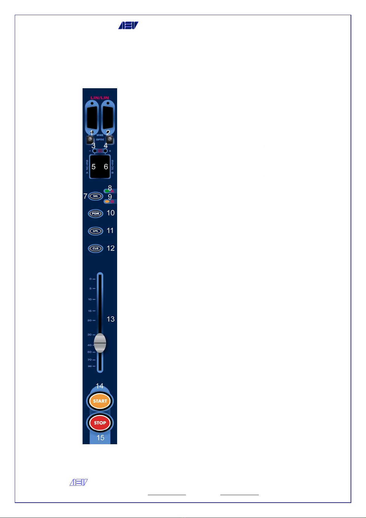
1 – 15-
pin connector (microphone input),
the pin-out out-
pin is provided in the
technical section
2 - 15-
pin connector (line input), Connettore
15 poli the pin-out
out
technical section
3 -
Trimmer for adjusting the input levels
from 0 to + 30 dB for very low
microphones
4 –
Button for the fine adjustment of the
input levels (max attenuation
is a shared button but its func
customised for two inputs
5 -
Button for the fine adjustment of the
input levels (max amplification: +12dB)
This is a shared button but its function is
customised for two inputs
6 - Dip-
switch for microphone channel setup
(Timer, Insert, Talk
Auto-
Start, Echo and Remote)
7 - Dip-
switch for Line channel setup (Timer,
Talk Back, Mute, Tally, Auto
Remote)
8 –
Button for selecting the input source
(Micro or Line)
9 –
Light indicator, Micro input On
1 0 - Light
indicator, Line input On
1 1 –
Button for assigning the channel to the
PGM bus
1 2 -
Button for assigning the channel to the
UTL bus
1 3 –
Button for enabling CUE pre
1 4 - Fader
1 5 –
START button, the channel signal is
sent to the UTL and
enabled by buttons 11 and 12, the CUE is
disabled and a pulse is sent to the
optional remote control (if installed)
1 6
STOP button, the channel signal is no
longer sent to the PGM and/or UTL buses
selected A pulse is sent to the optional
r
emote control (if installed)
If capacitor microphones are used, the
Phantom power supply will be wired to
connector 1, see technical section
Argelato (BO) Italy
6
pin connector (microphone input),
pin is provided in the
pin connector (line input), Connettore
out
-pin is provided in the
Trimmer for adjusting the input levels
from 0 to + 30 dB for very low
-tone
Button for the fine adjustment of the
input levels (max attenuation
– 12dB) This
is a shared button but its func
tion is
customised for two inputs
Button for the fine adjustment of the
input levels (max amplification: +12dB)
This is a shared button but its function is
customised for two inputs
switch for microphone channel setup
(Timer, Insert, Talk
- Back, Mute, Tally,
Start, Echo and Remote)
switch for Line channel setup (Timer,
Talk Back, Mute, Tally, Auto
-Start, Echo and
Button for selecting the input source
Light indicator, Micro input On
indicator, Line input On
Button for assigning the channel to the
Button for assigning the channel to the
Button for enabling CUE pre
-listening
START button, the channel signal is
sent to the UTL and
/or PGM buses
enabled by buttons 11 and 12, the CUE is
disabled and a pulse is sent to the
optional remote control (if installed)
STOP button, the channel signal is no
longer sent to the PGM and/or UTL buses
selected A pulse is sent to the optional
emote control (if installed)
If capacitor microphones are used, the
Phantom power supply will be wired to
connector 1, see technical section
AEV Broadcast
Web site
Line - Line Module
AEV SYNAPSE - ON AIR CONSOLE
AEV Broadcast
Srl – via della Tecnica 33 – 40050
Argelato (BO) Italy
Web site
www aev eu e-mail info@aev eu
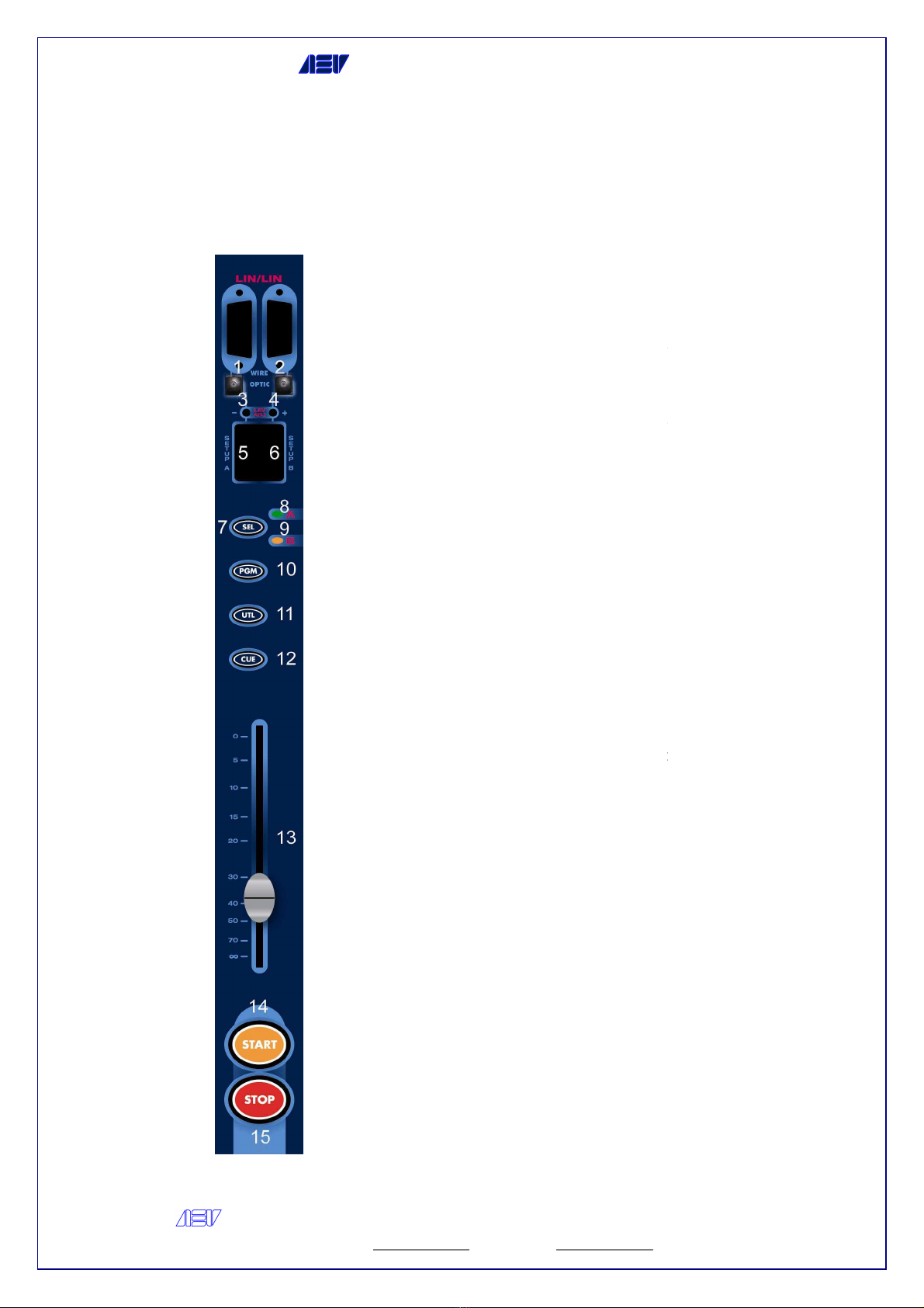
1 - 15-
pin input connector, line A input, the pin
out is available in the technical section
2 - 15-
pin input connector, line B input, the pin
out is available in the technical section
3 - Button
for the fine adjustment of input levels
(max attenuation: -
12 dB) This is a shared
button but its function is customised for two
inputs
4 -
Button for the fine adjustment of the input
levels (max amplification: +12dB) This is a
shared button but its
function is customised for
two inputs
5 -
Setup of line A channel
6 -
Setup of line B channel
7 -
Button for selecting the input source (Line A
or Line B)
8 -
Indicator light, Line A input On
9 -
Indicator light, Line B input On
1 0 - Button for ass
igning the channel to the PGM
bus
1 1 -
Button for assigning the channel to the UTL
bus
1 2 -
Button for enabling CUE pre
1 3 - Fader
1 4 -
START button: the channel signal is sent to
the PGM and/or UTL buses
selected by buttons 11 and 12 CU
and a pulse is sent to the optional remote control
(if installed)
1 5 –
STOP button: the channel signal is sent to
the PGM and/or UTL buses
selected and a pulse is sent to the
control (if installed)
Argelato (BO) Italy
7
pin input connector, line A input, the pin
-
out is available in the technical section
pin input connector, line B input, the pin
-
out is available in the technical section
for the fine adjustment of input levels
12 dB) This is a shared
button but its function is customised for two
Button for the fine adjustment of the input
levels (max amplification: +12dB) This is a
function is customised for
Setup of line A channel
Setup of line B channel
Button for selecting the input source (Line A
Indicator light, Line A input On
Indicator light, Line B input On
igning the channel to the PGM
Button for assigning the channel to the UTL
Button for enabling CUE pre
-listening
START button: the channel signal is sent to
the PGM and/or UTL buses
selected by buttons 11 and 12 CU
E is inactivated
and a pulse is sent to the optional remote control
STOP button: the channel signal is sent to
the PGM and/or UTL buses
selected and a pulse is sent to the
optional remote
AEV Broadcast
Web site
Double Digital input Module
AEV SYNAPSE - ON AIR CONSOLE
AEV Broadcast
Srl – via della Tecnica 33 – 40050
Argelato (BO) Italy
Web site
www aev eu e-mail info@aev eu
Double Digital input Module
1 -
DB9 / Optical input connectors, line A input, the
pin-
out is available in the technical section
2 - DB9 / Optical
input connectors, line B input, the
pin-
out is available in the technical section
3 -
Button for the fine adjustment of input levels
(max attenuation -
6 dB) This is a shared button but its function is
customised for two inputs
4 - Button for the fine
adjustment of the input
levels (max 0dB) This is a shared button but its
function is customised for two inputs
5 -
Setup of line A channel
6 -
Setup of line B channel
7 -
Button for selecting the input source (Line A or
Line B)
8 - Indicator light, Li
ne A input On
9 -
Indicator light, Line B input On
1 0 -
Button for assigning the channel to the PGM
bus
1 1 -
Button for assigning the channel to the UTL
bus
1 2 -
Button for enabling CUE pre
1 3 - Fader
1 4 -
START button: the channel
the PGM and/or UTL buses selected by buttons 11
and 12 CUE is inactivated and a pulse is sent to
the optional remote control (if installed)
1 5 –
STOP button: the channel signal i
PGM and/or UTL buses selected and a pulse is sent
to the optional remote control (if installed)
Argelato (BO) Italy
8
DB9 / Optical input connectors, line A input, the
out is available in the technical section
input connectors, line B input, the
out is available in the technical section
Button for the fine adjustment of input levels
6 dB) This is a shared button but its function is
customised for two inputs
adjustment of the input
levels (max 0dB) This is a shared button but its
function is customised for two inputs
Setup of line A channel
Setup of line B channel
Button for selecting the input source (Line A or
ne A input On
Indicator light, Line B input On
Button for assigning the channel to the PGM
Button for assigning the channel to the UTL
Button for enabling CUE pre
-listening
START button: the channel
signal is sent to
the PGM and/or UTL buses selected by buttons 11
and 12 CUE is inactivated and a pulse is sent to
the optional remote control (if installed)
STOP button: the channel signal i
s sent to the
PGM and/or UTL buses selected and a pulse is sent
to the optional remote control (if installed)

AEV Broadcast
Web site
Telephone module
AEV SYNAPSE - ON AIR CONSOLE
AEV Broadcast
Srl – via della Tecnica 33 – 40050
Argelato (BO) Italy
Web site
www aev eu e-mail info@aev eu
1 -
Connector RJ45 for telephone service
2 -
Connector RJ45 for telephone line
3 - Button for the fine
adjustment of the input
levels (max attenuation:
4 -
Button for the fine adjustment of the input
levels (max amplification: +12dB)
5 - Dip-
switch for telephone channel set
Mute, Tally, Auto-
Start, Echo, Line and Remote
gain)
6 - HO
OK button for telephone hook
7 -
Indicator light for incoming telephone calls
8 -
Indicator light for line hook
9 -
Button for assigning the channel to the PGM
bus
1 0 -
Button for assigning the channel to the UTL
bus
1 1 -
Button for enabling C
1 2 - Fader
1 3 -
START button: the channel signal is sent to
the PGM and/or UTL buses selected by buttons 11
and 12, CUE is inactivated and a pulse is sent to
the optional remote control (if installed)
1 4 -
STOP button: the channel
the PGM and/or UTL buses selected and a pulse is
sent to the optional remote control (if installed)
Operation
When the CALL Led is flashing, this means that a
telephone call is being received
Press the HOOK button to hook up the tel
line; the respective Led lights up To disable the
telephone line, press the HOOK button again
The “Meeting” function to connect two telephone
users is enabled only if the respective telephone
modules are in PGM or UTL mode
The telephone modules i
n “St by” mode enable the
audio functions on the PGM master module
The director can speak privately with the telephone
users on the respective telephone modules by
pressing the CUE button and Tb button so that
his/her microphone can be activated
The
speaker can talk privately to the telephone
users on the respective modules if the DJ has
pressed the CUE button on the respective module,
the CUE bus has been assigned to the Control
Studio output,
the channel has been switched over
to STOP mode and the TB button is pressed (Mike
A connector); this button is connected to the
microphone module
Argelato (BO) Italy
9
Connector RJ45 for telephone service
Connector RJ45 for telephone line
adjustment of the input
levels (max attenuation:
- 12dB)
Button for the fine adjustment of the input
levels (max amplification: +12dB)
switch for telephone channel set
-up (Timer,
Start, Echo, Line and Remote
OK button for telephone hook
-up
Indicator light for incoming telephone calls
Indicator light for line hook
-up
Button for assigning the channel to the PGM
Button for assigning the channel to the UTL
Button for enabling C
UE pre-listening
START button: the channel signal is sent to
the PGM and/or UTL buses selected by buttons 11
and 12, CUE is inactivated and a pulse is sent to
the optional remote control (if installed)
STOP button: the channel
signal is not sent to
the PGM and/or UTL buses selected and a pulse is
sent to the optional remote control (if installed)
When the CALL Led is flashing, this means that a
telephone call is being received
Press the HOOK button to hook up the tel
ephone
line; the respective Led lights up To disable the
telephone line, press the HOOK button again
The “Meeting” function to connect two telephone
users is enabled only if the respective telephone
modules are in PGM or UTL mode
n “St by” mode enable the
audio functions on the PGM master module
The director can speak privately with the telephone
users on the respective telephone modules by
pressing the CUE button and Tb button so that
his/her microphone can be activated
speaker can talk privately to the telephone
users on the respective modules if the DJ has
pressed the CUE button on the respective module,
the CUE bus has been assigned to the Control
the channel has been switched over
to STOP mode and the TB button is pressed (Mike
A connector); this button is connected to the

AEV SYNAPSE
AEV Broadcast
Srl
Web site
Tone Control Module
AEV SYNAPSE
- ON AIR CONSOLE
Srl
– via della Tecnica 33 – 40050
Argelato (BO) Italy
Web site
www aev eu e-mail info@aev eu
The Tone Control Mo
dule must be inserted on
the left of the Master Module
The Tone Control Module has three different
settings: 1 Treble, 2 Mid, 3 Bass
These commands use encoders that work by
pressing and rotating them
In order to set the equalization of a channel,
it is
necessary to select the A or B input of
the channel and press the Cue button The
leds on the Tone Control Module will show the
current equalization (1 led for each band; the
default is 0, 0, 0) The "editing" function is
activate by pressing the encoder
one for each encoder, start blinking); now it
is possible to modify the equalization In
order to save the equalization press one of
the encoders
In case a Cue button is pressed without
intention while the editing process is on, the
equalizatio
n is saved and it is showed the one
of the channel related at the Cue button
pressed
When the settings for each cannel (A and B
inputs) have been done and none of
the Cue button is pressed the Tone Co
Module leds are switched off
Argelato (BO) Italy
10
dule must be inserted on
the left of the Master Module
The Tone Control Module has three different
settings: 1 Treble, 2 Mid, 3 Bass
These commands use encoders that work by
pressing and rotating them
In order to set the equalization of a channel,
necessary to select the A or B input of
the channel and press the Cue button The
leds on the Tone Control Module will show the
current equalization (1 led for each band; the
default is 0, 0, 0) The "editing" function is
activate by pressing the encoder
(the leds,
one for each encoder, start blinking); now it
is possible to modify the equalization In
order to save the equalization press one of
In case a Cue button is pressed without
intention while the editing process is on, the
n is saved and it is showed the one
of the channel related at the Cue button
When the settings for each cannel (A and B
inputs) have been done and none of
the Cue button is pressed the Tone Co
ntrol
Module leds are switched off

AEV SYNAPSE
AEV Broadcast
Srl
Web site
Tone Control and Digital Outs Module
AEV SYNAPSE
- ON AIR CONSOLE
Srl
– via della Tecnica 33 – 40050
Argelato (BO) Italy
Web site
www aev eu e-mail info@aev eu
Tone Control and Digital Outs Module
1 -
DB9 / Optical connectors, PGM AES3
digital outputs
2 - DB9 / Optical
connectors, UTL AES3 digital
outputs
3 - DIP-
Switch used for PGM output Sample
Rate setting
4 - DIP-
Switch used for UTL output Sample
Rate setting
The Tone Control Module has three different
settings: 5 Treble, 6 Mid, 7 Bass
These commands use encoders
pressing and rotating them
In order to set the equalization of a channel,
it is necessary to select the A or B input of
the channel and press the Cue button The
leds on the Tone Control Module will show the
current equalization (1 led for e
default is 0, 0, 0) The "editing" function is
activate by pressing the encoder (the leds,
one for each encoder, start blinking); now it
is possible to modify the equalization In
order to save the equalization press one of
the encoders
In
case a Cue button is pressed without
intention while the editing process is on, the
equalization is saved and it is showed the one
of the channel related at the Cue button
pressed
When the settings for each cannel (A and B
inputs) have been done and none
the Cue button is pressed the Tone Control
Module leds are switched off
Argelato (BO) Italy
11
DB9 / Optical connectors, PGM AES3
connectors, UTL AES3 digital
Switch used for PGM output Sample
-
Switch used for UTL output Sample
-
The Tone Control Module has three different
settings: 5 Treble, 6 Mid, 7 Bass
These commands use encoders
that work by
pressing and rotating them
In order to set the equalization of a channel,
it is necessary to select the A or B input of
the channel and press the Cue button The
leds on the Tone Control Module will show the
current equalization (1 led for e
ach band; the
default is 0, 0, 0) The "editing" function is
activate by pressing the encoder (the leds,
one for each encoder, start blinking); now it
is possible to modify the equalization In
order to save the equalization press one of
case a Cue button is pressed without
intention while the editing process is on, the
equalization is saved and it is showed the one
of the channel related at the Cue button
When the settings for each cannel (A and B
inputs) have been done and none
of
the Cue button is pressed the Tone Control
Module leds are switched off
AEV Broadcast
Web site
Master module
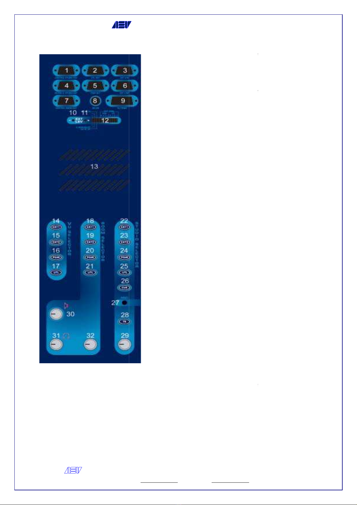
1 -
9 pin connector, Control Studio output
2 -
9 pin connector, UTL master output
3 -
9 pin connector, External input, EXT 2 IN
4 -
9 pin connector, Muted Control Studio output
5 -
9 pin connector, PGM Master output
6 -
9 pin connector, External input, EXT 1 IN
7 -
9 pin connector, Control Room output
8 - 6 3-mm jack connector to t
he OAL (On Air
Light)
9 - Service connector to join the Vu
-
restart timer control (if any)
AEV SYNAPSE - ON AIR CONSOLE
AEV Broadcast
Srl – via della Tecnica 33 – 40050
Argelato (BO) Italy
Web site
www aev eu e-mail info@aev eu
9 pin connector, Control Studio output
9 pin connector, UTL master output
9 pin connector, External input, EXT 2 IN
9 pin connector, Muted Control Studio output
9 pin connector, PGM Master output
9 pin connector, External input, EXT 1 IN
9 pin connector, Control Room output
he OAL (On Air
-
meter and a
1 0 -
Button for the fine adjustment of the EXT
input levels (max attenuation:
button is shared but its function is customised for
two
inputs To make the adjustments, enable the
desired input by using the VU selector
1 1 -
Button for the fine adjustment of the EXT
input levels (max amplification: +15dB) This
button is shared but its function is customised for
two inputs To make the ad
desired input by using the VU selector
1 2 - Dip-
switch for setting up the following
functions: Fader range, Control Room DIM, CUE
INT, PGM master level and UTL master level
1 3 -
Integrated loudspeaker
1 4 -
Button for enabling the
Meters Switched
1 5 -
Button for enabling the EXT 2 input for VU
Meters Switched
1 6 -
Button for enabling the PGM Master output for
VUMeters Switched
1 7 -
Button for enabling the UTL Master output for
VUMeters Switched
1 8 - Button
for enabling the EXT1 input for the
Control Room
1 9 -
Button for enabling the EXT2 input for the
Control Room
2 0 -
Button for enabling the PGM Master output for
the Control Room
2 1 -
Button for enabling the UTL Master output for
the Control Room
2 2 -
Button for enabling the EXT1 input for the
Control Studio
2 3 -
Button for enabling the EXT2 input for the
Control Studio
2 4 -
Button for enabling the PGM Master output for
the Control Studio
2 5 -
Button for enabling the UTL Master output for
the Control Studio
2 6 -
Button for enabling the CUE output for the
Control Studio
2 7 -
Service microphone to be used when the DJ
and the speaker are to talk on the telephone
without being overheard
2 8 -
Button to enable the “Talk Back” control
Press t
he button to activate the service microphone
so that it will be possible to talk to the Speaker
The button lights up when the Speaker is calling
the DJ
2 9 -
Potentiometer to adjust the Control Studio
output level
3 0 -
Potentiometer to adjust the integ
loudspeaker level (13)
3 1 -
Potentiometer to adjust Control Room output
level
Argelato (BO) Italy
12
Button for the fine adjustment of the EXT
input levels (max attenuation:
-15 dB) This
button is shared but its function is customised for
inputs To make the adjustments, enable the
desired input by using the VU selector
Button for the fine adjustment of the EXT
input levels (max amplification: +15dB) This
button is shared but its function is customised for
two inputs To make the ad
justments, enable the
desired input by using the VU selector
switch for setting up the following
functions: Fader range, Control Room DIM, CUE
INT, PGM master level and UTL master level
Integrated loudspeaker
Button for enabling the
EXT 1 input for VU-
Button for enabling the EXT 2 input for VU
-
Button for enabling the PGM Master output for
Button for enabling the UTL Master output for
for enabling the EXT1 input for the
Button for enabling the EXT2 input for the
Button for enabling the PGM Master output for
Button for enabling the UTL Master output for
Button for enabling the EXT1 input for the
Button for enabling the EXT2 input for the
Button for enabling the PGM Master output for
Button for enabling the UTL Master output for
Button for enabling the CUE output for the
Service microphone to be used when the DJ
and the speaker are to talk on the telephone
without being overheard
Button to enable the “Talk Back” control
he button to activate the service microphone
so that it will be possible to talk to the Speaker
The button lights up when the Speaker is calling
Potentiometer to adjust the Control Studio
Potentiometer to adjust the integ
rated
Potentiometer to adjust Control Room output

AEV Broadcast
Web site
3 2 -
Potentiometer to adjust the headphone output
General functions
Insert
This function is used to
route the microphone signals to the INSERT output section and not to
the analog bus The signal can therefore be used as an input in an external audio processor
Once the signal has been processed, it can be sent back to the INSERT input and passed to the
analog bus This function is enabled through connector 1 (pin 4 and 5, if the function is not used,
provide a jumper between these pins)
Phantom
This function is used to power up the capacitor microphones and can be enabled for all microphone
inputs The
function is activated through connector 1 (provide a jumper between pins 6 and 7)
Start
When
START button is press it lights up and enables the channel A pulse is sent to the
remote control (if the option is provided) In addition, the STOP and CUE
off if they were previously enabled
Cue
The CUE function (pre-
listening) can be enabled, according to the settings of the dip switches,
in Interlock
mode, i e when a CUE button of any module has been pressed, the one previously select
will be disabled or, in Standard
mode, the CUE function can be activated for one channel at the same
time as the other channels
Stop
When the STOP button is pressed it lights up, the channel is inactivated and a pulse is sent to
the remote control (if
the option is provided) In addition, the START lighted button goes out
Slider
The Slider controls the channel audio level and creates a Start condition (by increasing the audio
level) and a Stop condition (by decreasing the audio level) provided that th
have been enabled by using the relevant dip
remote controls also apply
Tally
When this function is enabled for a channel by using the dip
activated
The channel is in Start mode and is assigned to the PGM bus
Timer restart
When this function is enabled for a channel by using the dip
channel START button to send a restart command to the external TIMER (master module,
connector 9, pins 4 and 12), 250-
ms pulse
Fader Auto Start / Stop
When this function is enabled for a channel by using the dip
so that the channel can be automatically set for the START mode; move the slider down to
channel over to Stop mode
Setup threshold Auto START/STOP
Enable the Auto Start / Stop
through the
• Module status in the Start
• Place the cursor on the slider
on the threshold
• Press and hold the Stop button
for at least 6
stored
• Place the cursor on the slider
on the threshold
• Press and hold
the Start button for
stored
• Place the cursor on the slider
to the minimum value
minimum
No echo on cmd remote
When this function is enabled for a channel by using the dip
will be received from the outside, the channel switches over to START mode and no other
commands a
re given This function serves when pulsed start/stop devices that use a single wire
are provided The Start Echo would disable the same source On the other hand, in OFF mode,
the signal would be sent back to the output section
AEV SYNAPSE - ON AIR CONSOLE
AEV Broadcast
Srl – via della Tecnica 33 – 40050
Argelato (BO) Italy
Web site
www aev eu e-mail info@aev eu
Potentiometer to adjust the headphone output
level
route the microphone signals to the INSERT output section and not to
the analog bus The signal can therefore be used as an input in an external audio processor
Once the signal has been processed, it can be sent back to the INSERT input and passed to the
analog bus This function is enabled through connector 1 (pin 4 and 5, if the function is not used,
provide a jumper between these pins)
This function is used to power up the capacitor microphones and can be enabled for all microphone
function is activated through connector 1 (provide a jumper between pins 6 and 7)
START button is press it lights up and enables the channel A pulse is sent to the
remote control (if the option is provided) In addition, the STOP and CUE
lighted buttons go
listening) can be enabled, according to the settings of the dip switches,
mode, i e when a CUE button of any module has been pressed, the one previously select
mode, the CUE function can be activated for one channel at the same
When the STOP button is pressed it lights up, the channel is inactivated and a pulse is sent to
the option is provided) In addition, the START lighted button goes out
The Slider controls the channel audio level and creates a Start condition (by increasing the audio
level) and a Stop condition (by decreasing the audio level) provided that th
e specific functions
have been enabled by using the relevant dip
-
switches The description given above for the
When this function is enabled for a channel by using the dip
-
switches (DIP 7 ON), a stable contact is
The channel is in Start mode and is assigned to the PGM bus
When this function is enabled for a channel by using the dip
-
switches (DIP 1 ON), press the
channel START button to send a restart command to the external TIMER (master module,
ms pulse
When this function is enabled for a channel by using the dip
-
switches (DIP 8 ON), move the SLIDER up
so that the channel can be automatically set for the START mode; move the slider down to
through the
dip 8
on the threshold
chosen for the activation of
Auto Stop
for at least 6
sec Until the LED selection A /
on the threshold
chosen for the activation of
Auto Start
the Start button for
at least 6 sec Until the LED selection A /
to the minimum value
, then the maximum
and finally back
When this function is enabled for a channel by using the dip
-
switches (DIP 9 ON), a start signal
will be received from the outside, the channel switches over to START mode and no other
re given This function serves when pulsed start/stop devices that use a single wire
are provided The Start Echo would disable the same source On the other hand, in OFF mode,
the signal would be sent back to the output section
Argelato (BO) Italy
13
route the microphone signals to the INSERT output section and not to
the analog bus The signal can therefore be used as an input in an external audio processor
Once the signal has been processed, it can be sent back to the INSERT input and passed to the
analog bus This function is enabled through connector 1 (pin 4 and 5, if the function is not used,
This function is used to power up the capacitor microphones and can be enabled for all microphone
function is activated through connector 1 (provide a jumper between pins 6 and 7)
START button is press it lights up and enables the channel A pulse is sent to the
lighted buttons go
listening) can be enabled, according to the settings of the dip switches,
mode, i e when a CUE button of any module has been pressed, the one previously select
ed
mode, the CUE function can be activated for one channel at the same
When the STOP button is pressed it lights up, the channel is inactivated and a pulse is sent to
the option is provided) In addition, the START lighted button goes out
The Slider controls the channel audio level and creates a Start condition (by increasing the audio
e specific functions
switches The description given above for the
switches (DIP 7 ON), a stable contact is
switches (DIP 1 ON), press the
channel START button to send a restart command to the external TIMER (master module,
switches (DIP 8 ON), move the SLIDER up
so that the channel can be automatically set for the START mode; move the slider down to
switch the
Auto Stop
B flashes, so the data is
Auto Start
B flashes, so the data is
and finally back
to a
switches (DIP 9 ON), a start signal
will be received from the outside, the channel switches over to START mode and no other
re given This function serves when pulsed start/stop devices that use a single wire
are provided The Start Echo would disable the same source On the other hand, in OFF mode,

AEV Broadcast
Web site
OUT/AUX Configuration
The
mixer can be provided with the following inputs and outputs:
-
two external analog inputs EXT 1 and 2
- one digital PGM AES/EBU +
PGM analog output
- one digital UTL AES/EBU +
UTL analog output
Direct controls
Control Room Section
The Control Room
audio output level may be adjusted via the C Room potentiometer located on the
panel
EXT1
The following procedure can be performed by pressing the EXT1 button: input signal EXT1 is
sent to the Control Room output section and the function previously
Room bar is inactivated
EXT2
Press button EXT2 to perform the following procedure: the EXT2 input signal is sent to the Control
Room output section and the function previously enabled with the Control Room bar is inactivated
PGM
Press the PGM button to perform the following procedure: the PGM input signal is sent to the Control
Room output section and the function previously activated with the Control Room bar is disabled
UTL
Press the UTL button to perform the following procedur
Room output section and the function previously activated with the Control Room bar is disabled
Cue
Press the CUE button for the following procedures: the CUE bus signal is sent to the Control
Studio output
section and the Control Studio bus function previously activated is disabled
TB
Press the TB button (talk back) to send the service microphone signal to the buses selected from
the “AUX In/Out Setup” menu
WARNiNG
The microphone signal replaces the signal
Release the TB button to restore the previous operating state
PRIVATE calls to telephone hybrids (if any) can be only made by using the TB microphone signal
with the “TELCO” channel in STOP mode and CUE enabl
Headphones Section
The headphone audio output level is adjusted by using the “Headphone” potentiometer on the
panel A signal assigned to the Control Room is normally sent to the headphone output When
one of the CUE buttons of any channel is enabled,
signal There may be exceptions depending on whether the DIM function is enabled or not
CUE Speaker Section
Speaker Volume
Used to adjust the Speaker Monitor volume with the SYNAPSE mixer The signal to be sen
the loudspeaker is chosen from the “CUE configuration” menu
How to use the Talk-Back mode
Talk-
Back from Control Room ( Director)
The TB from the Control Room (director) can be sent to a Control Studio (DJ), TELEPHONE, UTL and
PGM
If the TB signal
is received from the Control Room, the internal microphone signal will be passed to the
Control Studio (Speaker) and replaces the audio system previously enabled
The same TB signal from the Control Room activates the Mute function in the Control Room outp
section in order to avoid Larsen effects
If TELCO 1 is in STOP mode and CUE ON, the TB signal is sent to TELCO 1 and not to the Control
Studio
This prevents the DJ from being disturbed by private telephone calls and vice
Talk Back from Control
Studio ( DJ)
The TB signal from the Control Studio (DJ) is sent to the Control Room (Director) and to the telephone
bus if the telephone module is in STOP mode (private telephone calls being made)
AEV SYNAPSE - ON AIR CONSOLE
AEV Broadcast
Srl – via della Tecnica 33 – 40050
Argelato (BO) Italy
Web site
www aev eu e-mail info@aev eu
mixer can be provided with the following inputs and outputs:
two external analog inputs EXT 1 and 2
PGM analog output
UTL analog output
audio output level may be adjusted via the C Room potentiometer located on the
The following procedure can be performed by pressing the EXT1 button: input signal EXT1 is
sent to the Control Room output section and the function previously
enabled with the Control
Press button EXT2 to perform the following procedure: the EXT2 input signal is sent to the Control
Room output section and the function previously enabled with the Control Room bar is inactivated
Press the PGM button to perform the following procedure: the PGM input signal is sent to the Control
Room output section and the function previously activated with the Control Room bar is disabled
Press the UTL button to perform the following procedur
e: the UTL input signal is sent to the Control
Room output section and the function previously activated with the Control Room bar is disabled
Press the CUE button for the following procedures: the CUE bus signal is sent to the Control
section and the Control Studio bus function previously activated is disabled
Press the TB button (talk back) to send the service microphone signal to the buses selected from
The microphone signal replaces the signal
that has been assigned to the preset outputs
Release the TB button to restore the previous operating state
PRIVATE calls to telephone hybrids (if any) can be only made by using the TB microphone signal
with the “TELCO” channel in STOP mode and CUE enabl
ed
The headphone audio output level is adjusted by using the “Headphone” potentiometer on the
panel A signal assigned to the Control Room is normally sent to the headphone output When
one of the CUE buttons of any channel is enabled,
the CUE signal will replace the Control Room
signal There may be exceptions depending on whether the DIM function is enabled or not
Used to adjust the Speaker Monitor volume with the SYNAPSE mixer The signal to be sen
the loudspeaker is chosen from the “CUE configuration” menu
Back from Control Room ( Director)
The TB from the Control Room (director) can be sent to a Control Studio (DJ), TELEPHONE, UTL and
is received from the Control Room, the internal microphone signal will be passed to the
Control Studio (Speaker) and replaces the audio system previously enabled
The same TB signal from the Control Room activates the Mute function in the Control Room outp
section in order to avoid Larsen effects
If TELCO 1 is in STOP mode and CUE ON, the TB signal is sent to TELCO 1 and not to the Control
This prevents the DJ from being disturbed by private telephone calls and vice
-
Studio ( DJ)
The TB signal from the Control Studio (DJ) is sent to the Control Room (Director) and to the telephone
bus if the telephone module is in STOP mode (private telephone calls being made)
Argelato (BO) Italy
14
audio output level may be adjusted via the C Room potentiometer located on the
The following procedure can be performed by pressing the EXT1 button: input signal EXT1 is
enabled with the Control
Press button EXT2 to perform the following procedure: the EXT2 input signal is sent to the Control
Room output section and the function previously enabled with the Control Room bar is inactivated
Press the PGM button to perform the following procedure: the PGM input signal is sent to the Control
Room output section and the function previously activated with the Control Room bar is disabled
e: the UTL input signal is sent to the Control
Room output section and the function previously activated with the Control Room bar is disabled
Press the CUE button for the following procedures: the CUE bus signal is sent to the Control
section and the Control Studio bus function previously activated is disabled
Press the TB button (talk back) to send the service microphone signal to the buses selected from
that has been assigned to the preset outputs
PRIVATE calls to telephone hybrids (if any) can be only made by using the TB microphone signal
The headphone audio output level is adjusted by using the “Headphone” potentiometer on the
panel A signal assigned to the Control Room is normally sent to the headphone output When
the CUE signal will replace the Control Room
signal There may be exceptions depending on whether the DIM function is enabled or not
Used to adjust the Speaker Monitor volume with the SYNAPSE mixer The signal to be sen
t to
The TB from the Control Room (director) can be sent to a Control Studio (DJ), TELEPHONE, UTL and
is received from the Control Room, the internal microphone signal will be passed to the
The same TB signal from the Control Room activates the Mute function in the Control Room outp
ut
If TELCO 1 is in STOP mode and CUE ON, the TB signal is sent to TELCO 1 and not to the Control
-
versa
The TB signal from the Control Studio (DJ) is sent to the Control Room (Director) and to the telephone
bus if the telephone module is in STOP mode (private telephone calls being made)

AEV Broadcast
Web site
Mic –
Line nput & nsert Pin
AEV SYNAPSE - ON AIR CONSOLE
AEV Broadcast
Srl – via della Tecnica 33 – 40050
Argelato (BO) Italy
Web site
www aev eu e-mail info@aev eu
Line nput & nsert Pin
-out Setup
Argelato (BO) Italy
15

AEV Broadcast
Web site
Mic -
Line nput connection
AEV SYNAPSE - ON AIR CONSOLE
AEV Broadcast
Srl – via della Tecnica 33 – 40050
Argelato (BO) Italy
Web site
www aev eu e-mail info@aev eu
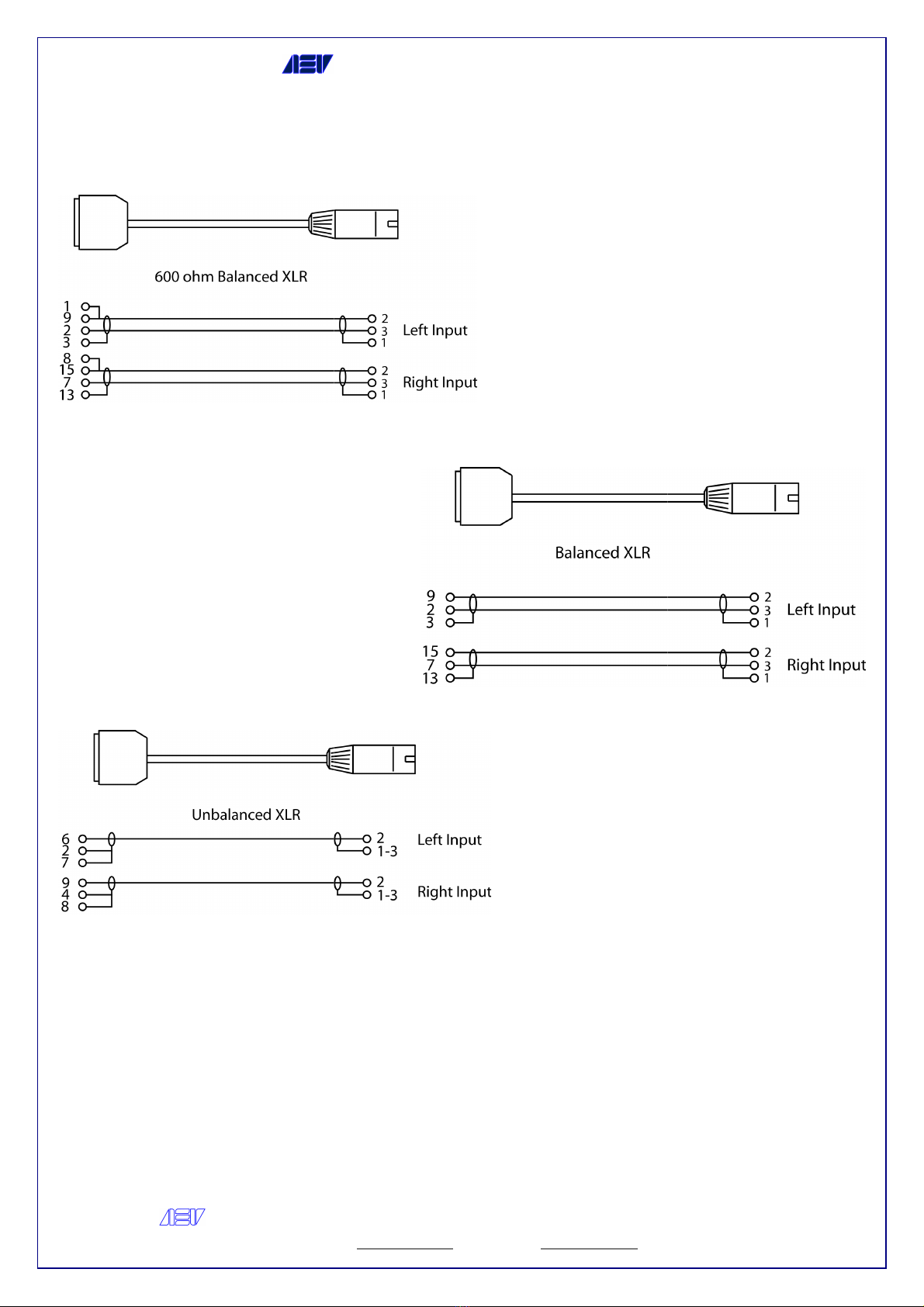
Line nput connection
Argelato (BO) Italy
16

AEV Broadcast
Web site
9
2
3
15
7
6
9
2
3
15
7
6
AEV SYNAPSE - ON AIR CONSOLE
AEV Broadcast
Srl – via della Tecnica 33 – 40050
Argelato (BO) Italy
Web site
www aev eu e-mail info@aev eu
Argelato (BO) Italy
17

AEV Broadcast
Web site
Mic - Line
D P SW TCH FUNCT ON NOTES
A B OFF ON
/ 1
Reset Timer When the
(through the VU-
Meter connector) to restart the external timer
1 /
Insert The INSERT telephone plug function is enabled (only through A)
2 2
DJ TEL When the channel is in STOP mode, the audi
telephone calls)
3 3 TB-
Studio/Room When the channel is in STOP mode, press the TB button to send
the signal to the output of the Control Room, Headphones and Speaker and the
Control Studio Mute is disabled
4 4
Speaker Mute When the channel changes over to START mode, the Speaker output
will be disabled 5 5 CR Mute When the channel changes over to START, the Control
Room output will be disabled
6 6
ST Mute When the channel changes over to START
disabled
7 7
ON AIR Tally When the channel changes over to START mode, with the PGM
activated, the ON AIR control contact closes
8 8
SLIDER S/S Move the slider up to START; move it down to STOP
9 9 R
EM ECHO The same command received , START or STOP, is sent to the
device connected
10 10
S/S STAB S/S IMPULSThe logic outputs are stable in the OFF position; pulsed in the
ON position (˜ 1 sec), if the option is provided
6
15
7
AEV SYNAPSE - ON AIR CONSOLE
AEV Broadcast
Srl – via della Tecnica 33 – 40050
Argelato (BO) Italy
Web site
www aev eu e-mail info@aev eu
D P SW TCH FUNCT ON NOTES
Reset Timer When the
channel switches over to START mode, a pulse is emitted
Meter connector) to restart the external timer
Insert The INSERT telephone plug function is enabled (only through A)
DJ TEL When the channel is in STOP mode, the audi
o signal is sent to TEL BUS (private
Studio/Room When the channel is in STOP mode, press the TB button to send
the signal to the output of the Control Room, Headphones and Speaker and the
Control Studio Mute is disabled
Speaker Mute When the channel changes over to START mode, the Speaker output
will be disabled 5 5 CR Mute When the channel changes over to START, the Control
Room output will be disabled
ST Mute When the channel changes over to START
mode, the Control Studio output is
ON AIR Tally When the channel changes over to START mode, with the PGM
activated, the ON AIR control contact closes
SLIDER S/S Move the slider up to START; move it down to STOP
EM ECHO The same command received , START or STOP, is sent to the
S/S STAB S/S IMPULSThe logic outputs are stable in the OFF position; pulsed in the
ON position (˜ 1 sec), if the option is provided
Argelato (BO) Italy
18
channel switches over to START mode, a pulse is emitted
Meter connector) to restart the external timer
Insert The INSERT telephone plug function is enabled (only through A)
o signal is sent to TEL BUS (private
Studio/Room When the channel is in STOP mode, press the TB button to send
the signal to the output of the Control Room, Headphones and Speaker and the
Speaker Mute When the channel changes over to START mode, the Speaker output
will be disabled 5 5 CR Mute When the channel changes over to START, the Control
mode, the Control Studio output is
ON AIR Tally When the channel changes over to START mode, with the PGM
SLIDER S/S Move the slider up to START; move it down to STOP
EM ECHO The same command received , START or STOP, is sent to the
S/S STAB S/S IMPULSThe logic outputs are stable in the OFF position; pulsed in the

AEV Broadcast
Web site
Line - Line nput Pin-out
AEV SYNAPSE - ON AIR CONSOLE
AEV Broadcast
Srl – via della Tecnica 33 – 40050
Argelato (BO) Italy
Web site
www aev eu e-mail info@aev eu
Argelato (BO) Italy
19
AEV Broadcast
Web site
Line - Line nput connection
AEV SYNAPSE - ON AIR CONSOLE
AEV Broadcast
Srl – via della Tecnica 33 – 40050
Argelato (BO) Italy
Web site
www aev eu e-mail info@aev eu
Argelato (BO) Italy
20
This manual suits for next models
1
Table of contents
Other AEV Recording Equipment manuals


