aevit VIC 2.0 User manual

VIC 2.0 Installation Manual
Table of Contents
2.
6. 6
6

1.1 OVERVIEW
VIC 2.0
VIC 2.0
VIC 2.0
VIC 2.0
VIC 2.0
Conrmation Functions
VIC 2.0
VIC 2.0
VIC 2.0
VIC 2.0VIC 2.0
VIC 2.0
VIC 2.0
2.
Dimmer
6.
Drive *
1.INTRODUCTION
1.2 HOW IT WORKS
1.3 SYSTEM COMPONENTS
VIC 2.0
1

2.WIRING VIC 2.0
21
2.1 STANDARD WIRING DIAGRAM

VIC 2.0
INSTALLATION STEP 1
VIC 2.0
VIC 2.0
INSTALLATION STEP 2
VIC 2.0 CPU
INSTALLATION STEP 3
3.INSTALLATION VIC 2.0
31
VIC 2.0 INSTALLATION
NOTE:

VIC 2.0 INSTALL MANUAL
32A
VIC 2.0 INSTALLATION
INSTALLATION STEP 4A - TWO SPEAKERS
Connect the 8-cond speaker cable to the VIC 2.0
CPU and route the cables to the individual speak-
ers.
When VIC 2.0 is activated, the VIC 2.0 CPU sup-
plies enough power to drive TWO vehicle speak-
ers. EMC recommends that you interface directly
with the two front dash speakers or front door
speakers if no dash speakers are available. Be-
cause the OEM vehicles have several dierent au-
dio options available for each vehicle which, may
or may not include an additional power amplier,
EMC does NOT include vehicle specic wiring diagrams for the VIC 2.0 system. The left and right
front speaker wires will need to be cut AT THE SPEAKER. This will leave (4) wires, (2) radio side (RS)
and (2) speaker side (SS) on both the right and left sides of the vehicle. The connection to the speak-
ers MUST be on the nal pair of wires that are routed to the speakers. These wires may be connected
directly the back of the radio, or an additional power amplier which may be located under the front
seat or in the rear of the vehicle. The connection CANNOT be on the signal wires that are routed
from the radio to the power amplier (if one is installed). If vehicle schematics are available, use them
to match the VIC speaker wire polarity with the vehicle speaker polarity.
Locate the two front speakers and cut the two wires to each speaker so you have a vehicle side (VS)
and a speaker side (SS). Strip the wire back approx. 3/8 in, solder and heat shrink the VIC 2.0 speaker
cable wires according to the diagram below:
PIN # HARNESS WIRE
COLOR FUNCTION
5 WHITE + LEFT (SS)
6 YELLOW - LEFT (SS)
7 VIOLET + RIGHT (SS)
8 BLUE - RIGHT (SS)
PIN # HARNESS WIRE
COLOR FUNCTION
1 RED + LEFT (RS)
2 BLACK - LEFT (RS)
3 ORANGE + RIGHT (RS)
4 GREEN - RIGHT (RS)

VIC 2.0 INSTALL MANUAL
32B
VIC 2.0 INSTALLATION
INSTALLATION STEP 4B - SINGLE SPEAKER
The following diagram shows how to wiring the VIC 2.0 if only one OEM speaker is being used.
PIN # HARNESS WIRE
COLOR FUNCTION
5 WHITE + SPEAKER (SS)
8 BLUE - SPEAKER (SS)
PIN # HARNESS WIRE
COLOR FUNCTION
1 RED + SPEAKER (RS)
4 GREEN - SPEAKER (RS)

33
VIC 2.0 INSTALLATION
INSTALLATION STEP 5
VIC 2.0
NOT THE
MAIN RADIO POWER WIRE,
DO NOT CUT THE MAIN RADIO POWER WIRE
BECAUSE IT WILL LOSE THE SETTINGS FOR THE RADIO.
CAUTION:
wITCHED IgNITION RADIO ACTIVATION wIRE.
wARNINg:

VIC 2.0
VIC 2.0
VIC 2.0
INSTALLATION STEP 8
VIC 2.0VIC
2.0
INSTALLATION STEP 6
VIC 2.0
INSTALLATION STEP 7
34
VIC 2.0 INSTALLATION
INSTALLATION STEP 9

INSTALLATION STEP 10 - INSTALLING THE VIC 2.0 MICROPHONE
35
VIC 2.0 INSTALLATION
VIC 2.0
MICROPHONE
FINE ADJUSTMENT
SECTION
GROSS ADJUSTMENT
SECTION MICROPHONE
WIRE
BASE PLATE
VIC 2.0
It is necessary to position the microphone with the client1. in the vehicle:
VIC 2.0
Avoid sharp bends of the Gross adjustment section of the microphone:2.
CORRECT INCORRECT
The microphone should be as un-intrusive as possible:3.

VIC 2.0
VIC 2.0TrainingRec-
ognition
MUST
QUIET
VIC 2.0.
VIC 2.0
Recognition
Training.
VIC 2.0
4.TRAINING
VIC 2.0
41
4.1 IMPORTANT CRITERIA FOR TRAINING

VIC 2.0
VIC 2.0
VIC 2.0: “You now have voice activation”
VIC 2.0: “Please select Training Mode”
STEP 1
VIC 2.0
STEP 2
STEP 3
VIC 2.0
STEP 4
42
4.2 ACCESSING VIC 2.0 TRAINING MODE

VIC 2.0 “Training mode part 2.”
VIC 2.0
VIC 2.0 “Training Aborted.”
VIC 2.0
“Training completed”
VIC 2.0
“You now have voice activation.”
VIC 2.0
VIC 2.0“Training Mode is selected. Please press the listen switch
now.”
VIC 2.0
VIC 2.0“Please say LEFT.”
VIC 2.0”Please repeat LEFT.”
TRAINING STEP 1
TRAINING STEP 2
TRAINING STEP 3
43
4.3 TRAINING VIC 2.0

VIC 2.0
VIC 2.0
VIC 2.0“Louder recognized”
VIC 2.0
VIC 2.0
Conrmation Functions
VIC 2.0
VIC 2.0“Please conrm, drive”
VIC 2.0“Drive recognized”
OPERATION STEP 1
5.OPERATION VIC 2.0
51
VIC 2.0 OPERATION
OPERATION STEP 2

VIC 2.0
VIC 2.0
OPERATION STEP 3
52
VIC 2.0 OPERATION
VIC 2.0
VIC 2.0“Please conrm, start”
VIC 2.0“Start recognized”
OPERATION STEP 2 (CONT’D)
OPERATION STEP 4
VIC 2.0
VIC 2.0
VIC 2.0
NOTE:
VIC 2.0

VIC 2.0
VIC - Load Defaults:
VIC - Performance:
VIC 2.0
VIC - Volume:
VIC 2.0.
VIC Revision:
OPERATION STEP 5
53
VIC 2.0 OPERATION
VIC Revision: 02.03.01

2.
VIC 2.0
VIC 2.0.
6. FINAL TESTING VIC 2.0
7.SERVICE REQUIREMENTS VIC 2.0
6
Table of contents
Popular Control Unit manuals by other brands
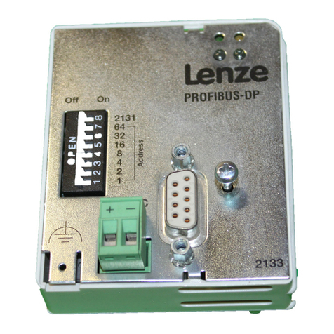
Lenze
Lenze EMF2133IB Communications manual

Hoft & Wessel
Hoft & Wessel HW 86010 Integration manual

Bosch
Bosch B442 installation manual
Symetrix
Symetrix SymNet Audio Matrix Control I/O quick start guide
Grundfos
Grundfos CIM 1 LON Series Installation and operating instructions
Vishay Precision Group
Vishay Precision Group LVDT Operating and installation instructions


