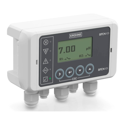
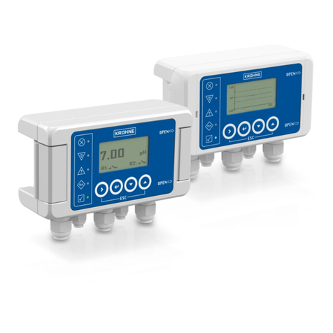
KROHNE SHD 200 User manual

Control unit for 4…20 mA/HART
®
field devices
Electronic Revision: ER 1.0.0
SHD 200
SHD 200SHD 200
SHD 200 Handbook
HandbookHandbook
Handbook
© KROHNE 08/2020 - 4007792902 - MA SHD 200 R02 en
The documentation is only complete when used in combination with the relevant
documentation for the field device.

All rights reserved. It is prohibited to reproduce this documentation, or any part thereof, without
the prior written authorisation of KROHNE Messtechnik GmbH.
Subject to change without notice.
2
www.krohne.com 08/2020 - 4007792902 - MA SHD 200 R02 en
Copyright 2020 by
KROHNE Messtechnik GmbH - Ludwig-Krohne-Str. 5 - 47058 Duisburg (Germany)
:
IMPRINT
:::::::::::::::::::::::::::::::::::::::

CONTENTS
3
www.krohne.com08/2020 - 4007792902 - MA SHD 200 R02 en
SHD 200
1 Safety instructions 5
1.1 Certifications .................................................................................................................... 5
1.2 Software history ............................................................................................................... 5
1.3 Intended use ..................................................................................................................... 6
1.4 Safety instructions from the manufacturer ..................................................................... 6
1.4.1 Copyright and data protection ................................................................................................ 6
1.4.2 Disclaimer ............................................................................................................................... 7
1.4.3 Product liability and warranty ................................................................................................ 7
1.4.4 Information concerning the documentation........................................................................... 7
1.4.5 Warnings and symbols used................................................................................................... 8
1.5 Safety instructions for the operator................................................................................. 8
2 Device description 9
2.1 Scope of delivery............................................................................................................... 9
2.2 Device description .......................................................................................................... 10
2.3 Nameplate ...................................................................................................................... 11
3 Installation 12
3.1 General notes on installation ......................................................................................... 12
3.2 Storage and transport .................................................................................................... 12
3.3 Point-to-Point connection - analogue / digital mode .................................................... 13
3.4 Pre-installation requirements ....................................................................................... 14
3.5 Opening the housing....................................................................................................... 15
3.6 Wall mounting ................................................................................................................ 16
3.6.1 Housing ................................................................................................................................. 16
4 Electrical connections 17
4.1 Safety instructions.......................................................................................................... 17
4.2 Important device-specific notes on electrical connection............................................. 17
4.3 Connection diagram overview ........................................................................................ 18
4.4 Connecting the field device cable .................................................................................. 19
4.5 Connecting the second current output .......................................................................... 20
4.6 Connecting the relay outputs ......................................................................................... 21
4.7 Connecting the external HART adapter ......................................................................... 22
4.8 Power supply .................................................................................................................. 22
5 Start-up 24
5.1 Start-up........................................................................................................................... 24
6 Operation 26
6.1 Operating elements........................................................................................................ 26
6.2 Function tables ............................................................................................................... 27
CONTENTS
4
www.krohne.com 08/2020 - 4007792902 - MA SHD 200 R02 en
SHD 200
6.3 Menu mode ..................................................................................................................... 42
6.3.1 Menu mode structure ........................................................................................................... 43
6.3.2 Status messages and diagnostic information ...................................................................... 44
6.4 Setup............................................................................................................................... 49
6.4.1 Configuration of measurement page.................................................................................... 49
6.4.2 Number of format ................................................................................................................. 54
6.4.3 Configuration of Loop 1......................................................................................................... 54
6.4.4 Configuration of Loop 2......................................................................................................... 55
6.4.5 Function of relay 1 + 2........................................................................................................... 56
6.4.6 Configuration of relay 1+2..................................................................................................... 59
6.4.7 Illumination Setting............................................................................................................... 64
6.4.8 Overflow sign and exponential format.................................................................................. 65
7 Service 66
7.1 Maintenance and repair ................................................................................................. 66
7.2 Spare parts availability...................................................................................................66
7.3 Availability of services .................................................................................................... 66
7.4 Returning the device to the manufacturer..................................................................... 66
7.4.1 General information.............................................................................................................. 66
7.4.2 Form (for copying) to accompany a returned device............................................................ 67
7.5 Disposal .......................................................................................................................... 67
7.5.1 Disassembly and recycling ................................................................................................... 68
8 Technical data 70
8.1 Technical data................................................................................................................. 70
8.2 Dimensions ..................................................................................................................... 72
9 Notes 73

SAFETY INSTRUCTIONS
1
5
SHD 200
www.krohne.com08/2020 - 4007792902 - MA SHD 200 R02 en
1.1 Certifications
The device meets the essential requirements of the EU directives. The CE marking indicates the
conformity of the product with the union legislation applying to the product and providing for CE
marking.
For full information of the EU directives and standards and the approved certifications, please
refer to the EU declaration on the KROHNE website.
Other approvals and standard
•NAMUR recommendation NE 6, NE 21, NE 43, NE 53, NE 107
1.2 Software history
Changes and effect on compatibility
CE marking
INFORMATION!
In the table below, "x" is a placeholder for possible multi-digit alphanumeric combinations,
depending on the available version.
1Downwards compatible changes and fault repair with no effect on operation (e.g. spelling
mistakes on display)
2-_ Downwards compatible hardware and/or software change of interfaces:
HHART
®
PPROFIBUS
FFoundation Fieldbus
MModbus
Xall interfaces
3-_ Downwards compatible hardware and/or software change of inputs and outputs:
ICurrent output
F, P Frequency / pulse output
SStatus output
CControl input
CI Current input
Xall inputs and outputs
4Downwards compatible changes with new functions
5Incompatible changes, i.e. electronic equipment must be changed.
Release date Electronic
revision
Changes and
compatibility
Documentation
04.10.2019 ER 1.0.0 MA SHD 200 R01

1
SAFETY INSTRUCTIONS
6
SHD 200
www.krohne.com 08/2020 - 4007792902 - MA SHD 200 R02 en
1.3 Intended use
The SHD 200 is a control unit for 4...20 mA/HART
®
field devices. The intended use is process
control by using the relays, the second current output and the NAMUR NE 107 signalisation by
LEDs for the HART
®
parameters of the connected field device. The device has been constructed
for indoor and outdoor use below the maximum altitude of 2000 m / 6562 ft.
1.4 Safety instructions from the manufacturer
1.4.1 Copyright and data protection
The contents of this document have been created with great care. Nevertheless, we provide no
guarantee that the contents are correct, complete or up-to-date.
The contents and works in this document are subject to copyright. Contributions from third
parties are identified as such. Reproduction, processing, dissemination and any type of use
beyond what is permitted under copyright requires written authorisation from the respective
author and/or the manufacturer.
The manufacturer tries always to observe the copyrights of others, and to draw on works created
in-house or works in the public domain.
The collection of personal data (such as names, street addresses or e-mail addresses) in the
manufacturer's documents is always on a voluntary basis whenever possible. Whenever
feasible, it is always possible to make use of the offerings and services without providing any
personal data.
We draw your attention to the fact that data transmission over the Internet (e.g. when
communicating by e-mail) may involve gaps in security. It is not possible to protect such data
DANGER!
For devices used in hazardous areas, additional safety notes apply; please refer to the Ex
documentation.
CAUTION!
Responsibility for the use of the measuring devices with regard to suitability, intended use and
corrosion resistance of the used materials against the measured fluid lies solely with the
operator.
WARNING!
If the device is not used according to the operating conditions (refer to chapter "Technical data"),
the intended protection could be affected.
INFORMATION!
This device is a Group 1, Class A device as specified within CISPR11:2009. It is intended for use in
industrial environment. There may be potential difficulties in ensuring electromagnetic
compatibility in other environments, due to conducted as well as radiated disturbances.
INFORMATION!
The manufacturer is not liable for any damage resulting from improper use or use for other than
the intended purpose.

SAFETY INSTRUCTIONS
1
7
SHD 200
www.krohne.com08/2020 - 4007792902 - MA SHD 200 R02 en
completely against access by third parties.
We hereby expressly prohibit the use of the contact data published as part of our duty to publish
an imprint for the purpose of sending us any advertising or informational materials that we have
not expressly requested.
1.4.2 Disclaimer
The manufacturer will not be liable for any damage of any kind by using its product, including,
but not limited to direct, indirect or incidental and consequential damages.
This disclaimer does not apply in case the manufacturer has acted on purpose or with gross
negligence. In the event any applicable law does not allow such limitations on implied warranties
or the exclusion of limitation of certain damages, you may, if such law applies to you, not be
subject to some or all of the above disclaimer, exclusions or limitations.
Any product purchased from the manufacturer is warranted in accordance with the relevant
product documentation and our Terms and Conditions of Sale.
The manufacturer reserves the right to alter the content of its documents, including this
disclaimer in any way, at any time, for any reason, without prior notification, and will not be liable
in any way for possible consequences of such changes.
1.4.3 Product liability and warranty
The operator shall bear responsibility for the suitability of the device for the specific purpose.
The manufacturer accepts no liability for the consequences of misuse by the operator. Improper
installation or operation of the devices (systems) will cause the warranty to be void. The
respective "Standard Terms and Conditions" which form the basis for the sales contract shall
also apply.
1.4.4 Information concerning the documentation
To prevent any injury to the user or damage to the device it is essential that you read the
information in this document and observe applicable national standards, safety requirements
and accident prevention regulations.
If this document is not in your native language and if you have any problems understanding the
text, we advise you to contact your local office for assistance. The manufacturer can not accept
responsibility for any damage or injury caused by misunderstanding of the information in this
document.
This document is provided to help you establish operating conditions, which will permit safe and
efficient use of this device. Special considerations and precautions are also described in the
document, which appear in the form of icons as shown below.

1
SAFETY INSTRUCTIONS
8
SHD 200
www.krohne.com 08/2020 - 4007792902 - MA SHD 200 R02 en
1.4.5 Warnings and symbols used
Safety warnings are indicated by the following symbols.
• HANDLING
HANDLINGHANDLING
HANDLING
This symbol designates all instructions for actions to be carried out by the operator in the
specified sequence.
iRESULT
RESULTRESULT
RESULT
This symbol refers to all important consequences of the previous actions.
1.5 Safety instructions for the operator
DANGER!
This warning refers to the immediate danger when working with electricity.
DANGER!
This warning refers to the immediate danger of burns caused by heat or hot surfaces.
DANGER!
This warning refers to the immediate danger when using this device in a hazardous atmosphere.
DANGER!
These warnings must be observed without fail. Even partial disregard of this warning can lead to
serious health problems and even death. There is also the risk of seriously damaging the device
or parts of the operator's plant.
WARNING!
Disregarding this safety warning, even if only in part, poses the risk of serious health problems.
There is also the risk of damaging the device or parts of the operator's plant.
CAUTION!
Disregarding these instructions can result in damage to the device or to parts of the operator's
plant.
INFORMATION!
These instructions contain important information for the handling of the device.
LEGAL NOTICE!
This note contains information on statutory directives and standards.
WARNING!
In general, devices from the manufacturer may only be installed, commissioned, operated and
maintained by properly trained and authorized personnel.
This document is provided to help you establish operating conditions, which will permit safe and
efficient use of this device.

DEVICE DESCRIPTION
2
9
SHD 200
www.krohne.com08/2020 - 4007792902 - MA SHD 200 R02 en
2.1 Scope of delivery
Optional accessories
Optional accessoriesOptional accessories
Optional accessories
•External HART
®
adapter
•Weather protection cover
•Wall mounting brackets
INFORMATION!
Inspect the packaging carefully for damages or signs of rough handling. Report damage to the
carrier and to the local office of the manufacturer.
INFORMATION!
Do a check of the packing list to make sure that you have all the elements given in the order.
INFORMATION!
Look at the device nameplate to ensure that the device is delivered according to your order.
Check for the correct supply voltage printed on the nameplate.
Figure 2-1: Example of the standard scope of delivery
1 Ordered device
2 Documentation

2
DEVICE DESCRIPTION
10
SHD 200
www.krohne.com 08/2020 - 4007792902 - MA SHD 200 R02 en
2.2 Device description
This 2-wire device can be connected to field devices with HART
®
protocol or 4…20 mA current
output. The two free programmable relays and the second current output allow process control.
Different customer-specific measurement pages with up to 4 displayed values enable a detailed
monitoring of the process. By using the second current output it is possible to use the backlight
and high brightness LEDs for NAMUR NE 107 status signalisation. A HART
®
access to the field
device is possible by connecting a HART
®
Handheld or HART
®
Modem to the internal or optional
external HART
®
adapter.
Figure 2-2: Device description
1 Display
2 Operation keys
3 Cable glands
4 High-brightness LEDs for NAMUR NE 107 status signalisation

DEVICE DESCRIPTION
2
11
SHD 200
www.krohne.com08/2020 - 4007792902 - MA SHD 200 R02 en
2.3 Nameplate
INFORMATION!
Look at the device nameplate to ensure that the device is delivered according to your order.
Check for the correct supply voltage printed on the nameplate.
Figure 2-3: Example of a nameplate
1 Manufacturer
2 Device name
3 CE marking
4 TAG number
5 Data matrix code (serial number),
Observe the operation and installation instruction, Ingress protection
China RoHS,
Electronic / Electric device waste marking,
6 Power supply data,
Parameter of measuring unit
7 Order code,
Manufacturing date,
Internet address of manufacturer
8 Electronic revision,
Serial number
9 Production order
SHD 200
IP66/67
LOOP 1: Ui=30V Ii=120mA Pi=1W Ci=45nF Li=0
LOOP 2: Ui=30V Ii=120mA Pi=1W Ci=25nF Li=0
RELAY: Ui=30V Ii=30mA Pi=100mW Ci=15nF Li=0

3
INSTALLATION
12
SHD 200
www.krohne.com 08/2020 - 4007792902 - MA SHD 200 R02 en
3.1 General notes on installation
3.2 Storage and transport
INFORMATION!
Inspect the packaging carefully for damages or signs of rough handling. Report damage to the
carrier and to the local office of the manufacturer.
INFORMATION!
Do a check of the packing list to make sure that you have all the elements given in the order.
INFORMATION!
Look at the device nameplate to ensure that the device is delivered according to your order.
Check for the correct supply voltage printed on the nameplate.
CAUTION!
Do not make any mechanical modifications to the device. This can result in the loss of proper
functionality, as well as the rights under the device warranty.
•
Store and transport the device in a dry, dust-free environment.
•
Store and transport the device in an environment with a temperature between -30...+70
°
C /
-22...+158
°
F.
•
The original packing is designed to protect the equipment. It has to be used if the device is
transported or sent back to the manufacturer to prevent damage of the device.

INSTALLATION
3
13
SHD 200
www.krohne.com08/2020 - 4007792902 - MA SHD 200 R02 en
3.3 Point-to-Point connection - analogue / digital mode
Point-to-Point connection between the field device and the HART
®
Master.
The current output of the field device is passive.
If using more than one HART
®
master please be aware of the correct configuration because only
one Primary master and one Secondary master are allowed. Two Primary masters or two
Secondary masters will cause communication errors.
Default master modes are
•SHD 200: Secondary
•HART
®
modem in PACTware: Primary
•HART
®
Field Communicator: Secondary (can’t be changed in most devices)
Figure 3-1: Overview point-to-point connection
1 HART
®
master with e.g. PACTware
TM
FDT/DTM
2 HART
®
modem
3 HART
®
signal
4 SHD 200
5 HART
®
master with HART
®
DD (for example field communicator)
6 HART
®
field device
7 Power supply for devices (slaves) with passive current output
8 Load ≥250 Ω(Ohm) (only required if not used in SHD 200)

3
INSTALLATION
14
SHD 200
www.krohne.com 08/2020 - 4007792902 - MA SHD 200 R02 en
These default master modes lead to the following use cases:
If you
•parameterise or calibrate your field device using PACTware with a HART
®
modem, the
master mode of the SHD 200 should be "Secondary"
•parameterise or calibrate your field device with a HART
®
field communicator, the master
mode of the SHD 200 should be "Primary"
•use PACTware with a HART
®
modem and a HART
®
field communicator at the same time, the
HART
®
functionality of the SHD 200 must be deactivated
•use a HART
®
PLC, find out its master mode and adapt the master mode of the SHD 200
appropriate
3.4 Pre-installation requirements
CAUTION!
Always note the following items to ensure a proper and safe installation:
•
Make sure that there is adequate space to the sides.
•
Protect the device from direct sunlight.
•
The device installed in control cabinets require adequate cooling, e.g. by fan or heat
exchanger.
•
Do not expose the device to intense vibration.
•
Use assembly materials and tools in compliance with the applicable occupational health and
safety directives (assembly materials and tools are not part of the scope of delivery).
•
Do not make any mechanical modifications to the device. This can result in the loss of proper
functionality, as well as the rights under the device warranty.
•
The device must not be heated by radiated heat (e.g. exposure to the sun) to a electronics
housing surface temperature above the maximum permissible ambient temperature. If it is
necessary to prevent damage from heat sources, a heat protection (e.g. sun shade) has to be
installed.
CAUTION!
The device must be suitable for the temperature specified (including chemical resistance).
INFORMATION!
Assembly materials and tools are not part of the delivery. Use the assembly materials and tools
in compliance with the applicable occupational health and safety directives.

INSTALLATION
3
15
SHD 200
www.krohne.com08/2020 - 4007792902 - MA SHD 200 R02 en
3.5 Opening the housing
All installation works on the electrical connections and mounting require to open the converter
housing:
• Put a small flat tool (e.g. screwdriver) into the right hinge lock and open the device 1.
• Lift up the housing 2.
iNow you have access to the electronic compartment and the possibility to mount the device
on a wall.
INFORMATION!
Clean and grease all threads each time you open the housing. Use only resin-free and acid-free
grease. Before closing the cover, ensure that the housing gasket is properly fitted, clean and
undamaged.
Opening the housing
Figure 3-2: Opening the housing

3
INSTALLATION
16
SHD 200
www.krohne.com 08/2020 - 4007792902 - MA SHD 200 R02 en
3.6 Wall mounting
3.6.1 Housing
1 Mark the holes with a suitable pen 1.
2 Drill the 4 holes and fasten the device securely to the wall 2.
CAUTION!
Always note the following items to ensure a proper and safe installation:
•
Make sure that there is adequate space to the sides.
•
The device must not be heated by radiated heat (e.g. exposure to the sun) to a electronics
housing surface temperature above the maximum permissible ambient temperature. If it is
necessary to prevent damage from heat sources, a heat protection (e.g. sun shade) has to be
installed.
•
Signal converters installed in control cabinets require adequate cooling, e.g. by fan or heat
exchanger.
•
Do not expose the signal converter to intense vibration.
•
Use assembly materials and tools in compliance with the applicable occupational health and
safety directives (assembly materials and tools are not part of the scope of delivery).
CAUTION!
Installation, assembly, start-up and maintenance may only be performed by appropriately
trained personnel. The regional occupational health and safety directives must always be
observed.
INFORMATION!
A mounting system with a minimum load force of 0.1 kN (for example FISCHER type UX10)
suitable for the background has to be applied.
Figure 3-3: Wall mounting of the housing
INFORMATION!
For outdoor mounting, we recommend the optional weather protection cover XGSH01000 for
wall and pipe mounting. For more flexibility and convenient mounting, we recommend wall
mounting brackets XGSH010020.

ELECTRICAL CONNECTIONS
4
17
SHD 200
www.krohne.com08/2020 - 4007792902 - MA SHD 200 R02 en
4.1 Safety instructions
4.2 Important device-specific notes on electrical connection
DANGER!
All work on the electrical connections may only be carried out with the power disconnected.
Take note of the voltage data on the nameplate!
DANGER!
Observe the national regulations for electrical installations!
DANGER!
For devices used in hazardous areas, additional safety notes apply; please refer to the Ex
documentation.
WARNING!
Observe without fail the local occupational health and safety regulations.
Any work done on the electrical components of the measuring device may only be carried out by
properly trained specialists.
INFORMATION!
Look at the device nameplate to ensure that the device is delivered according to your order.
Check for the correct supply voltage printed on the nameplate.
INFORMATION!
The SHD 200 is a loop powered device and has no function if no field device is connected.
INFORMATION!
Use only shielded cables for connection with the control system (e.g. PLC).

4
ELECTRICAL CONNECTIONS
18
SHD 200
www.krohne.com 08/2020 - 4007792902 - MA SHD 200 R02 en
4.3 Connection diagram overview
Figure 4-1: Connection diagram overview
Terminal designation Terminal assignments
JLoop2+
KLoop2-
FE Functional earth
SShield
A1 Sensor+
B1 Sensor-
A2 HART+
B2 HART-
CLoop 1+ (HART
®
resistor on board)
DLoop 1+ (External HART
®
resistor required)
ELoop1-
FRelay1+
GRelay1-
HRelay2+
IRelay2-
Table 4-1: Terminal designation with terminal assignments
LOOP2+
LOOP2-
FUNC. EARTH
SENSOR SHIELD
SENSOR+
SENSOR-
HART+
HART-
LOOP1+
LOOP1-
RELAY1+
RELAY1-
RELAY2+
RELAY2-
J K FE S A1 B1 A2 B2 DE F G H I
U2+ U2- S Sens+ U1+ U1-
Sens- R1+ R1- R2+ R2-
UUUU
LOOP2+
LOOP2-
FUNC. EARTH
SENSOR SHIELD
SENSOR+
SENSOR-
HART+
HART-
L
OO
P1+
LOOP1+
LOOP1-
RELAY1+
RELAY1-
RELAY2+
RELAY2-
J K FE S A1 B1 A2 B2
C
D E F G H I
U2+ U2- S Sens+ U1+ U1-
Sens- R1+ R1- R2+ R2-
UUUU

ELECTRICAL CONNECTIONS
4
19
SHD 200
www.krohne.com08/2020 - 4007792902 - MA SHD 200 R02 en
4.4 Connecting the field device cable
INFORMATION!
The device is equipped with an internal HART
®
access for the NonEx-version that offers the
opportunity to access the field device via HART
®
handheld or HART
®
modem.
CAUTION!
When connecting the power supply, always note the safety regulations of the current state of the
art. To avoid fatal injuries, destruction or damage of the device or measuring errors, also note
the following items:
•
Cables may only be connected when the power is switched off.
•
Always keep the housing of the device well closed if you do not perform any installation
works. The function of the housing is to protect the electronic equipment from dust and
moisture.
•
Check the nameplate and assure that the power supply meets the voltage of the device. The
device is loop powered and operates in the range of 20...30 VDC with a voltage drop < 4 VA. If
the power supply is below 20 VDC the device and field device will not work. If the power supply
is above 30 VDC the device and field device may be damaged/destroyed.
CAUTION!
Do not use the integrated 250 Ohm HART
®
resistor of the device, when using an Ex isolation
amplifier of third-party with integrated 250 Ohm HART
®
resistor.
Figure 4-2: Connecting the field device cable
LOOP2+
LOOP2-
FUNC. EARTH
SENSOR SHIELD
SENSOR+
SENSOR-
HART+
HART-
LOOP1+
LOOP1-
RELAY1+
RELAY1-
RELAY2+
RELAY2-
J K FE S A1 B1 A2 B2 D E F G H I
U2+ U2- S Sens+ U1+ U1-
Sens- R1+ R1- R2+ R2-
UUUU
LOOP2+
L
OOP2-
FU
N
C
. EA
R
TH
JK
FE
HAR
T+
H
A
R
T
-
LOOP1+
L
OO
P1+
LOO
P1-
RELA
Y1+
A
A
RELA
Y1-
AA
R
EL
A
Y2+
AA
RELA
Y2-
AA
A2 B2
C
D E F G H
F G
I
SENS
SENS
1
A
A
SENSOR SHIELD
SENSOR+
SSens+
S A1 B1
SENSOR-
Sens-
INFORMATION!
The cable glands installed by the manufacturer are designed for a cable diameter of 3...6,5 mm
for M12 and 5...10 mm for M16. If you are using cables with a larger diameter than 3...6,5 mm for
M12 and 5...10 mm for M16, you must replace the manufacturer
’
s cable glands with suitable
ones. The operator is responsible for the correct sealing of cable glands.

4
ELECTRICAL CONNECTIONS
20
SHD 200
www.krohne.com 08/2020 - 4007792902 - MA SHD 200 R02 en
4.5 Connecting the second current output
The second current output can be either used as current output for any HART
®
variable or as
power supply for backlight and LEDs for NAMUR NE 107 signalisation if supported by field device
(field device must support extended command 523: Read Condensed Status Mapping Array).
Figure 4-3: Connection of second current output
LOOP2+
LOOP2-
FUNC. EARTH
SENSOR SHIELD
SENSOR+
SENSOR-
HART+
HART-
LOOP1+
LOOP1-
RELAY1+
RELAY1-
RELAY2+
RELAY2-
J K FE S A1 B1 A2 B2 D E F G H I
U2+ U2- S Sens+ U1+ U1-
Sens- R1+ R1- R2+ R2-
UUUU
FU
N
C
. EA
R
TH
S
EN
SO
R
S
HIEL
D
SENSOR+
S
EN
SO
R-
HAR
T+
H
A
R
T
-
FE
S
A
1 B
1
A2 B2
LOOP1+
L
OO
P1+
LOO
P1-
RELA
Y1+
A
A
RELA
Y1-
AA
R
EL
A
Y2+
AA
RELA
Y2-
AA
C
D E F G H
F G
I
LOO
LOO
F
LOOP2+
LOOP2-
U2+ U2-
J K
Other manuals for SHD 200
3
Table of contents
Other KROHNE Control Unit manuals

KROHNE
KROHNE SMARTMAC 400 User manual

KROHNE
KROHNE OPTISWITCH 5100 C User manual

KROHNE
KROHNE OPTISWITCH 3100 C User manual

KROHNE
KROHNE Display and adjustment module for OPTISOUND... User manual

KROHNE
KROHNE ESK4 Series Wiring diagram

KROHNE
KROHNE SHD 200 Wiring diagram

KROHNE
KROHNE SHD 200 User manual

KROHNE
KROHNE SHD 200 User manual

KROHNE
KROHNE SMARTMAC 400 Wiring diagram

KROHNE
KROHNE SMARTMAC 200 W Wiring diagram