4
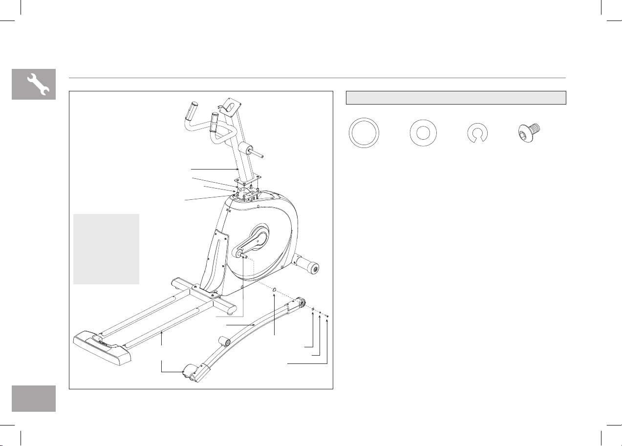
PIVOTING FOOT PADS
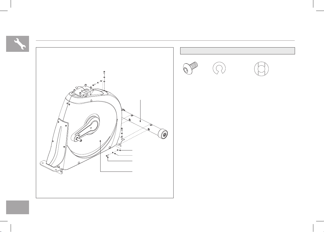
CRANK
TOP CAP
GUIDE RAIL SET
SPEAKERS
WATER BOTTLE HOLDER
UPPER HANDLEBAR
PULSE GRIPS
WARNING
CONSULT A PHYSICIAN PRIOR TO USING ANY
EXERCISE EQUIPMENT. POSSIBILITY OF
SERIOUS INJURY IF EQUIPMENT IS USED
IMPROPERLY. READ INSTRUCTION MANUAL
BEFORE USING. KEEP CHILDREN OFF AND
AWAY FROM THIS EQUIPMENT. FOR
CONSUMER USE ONLY.
AVERTISSEMENT
CONSULTER UN MÉDECIN AVANT D’UTILISER
CET ÉQUIPEMENT. POSSIBILITÉ DE BLESSURES
SÉRIEUSES SI L’ÉQUIPEMENT EST UTILISE DE
MANIÈRE INCORRECTE. AVANT USAGE, LIRE LE
GUIDE D’UTILISATEUR. NE PAS LAISSER CET
ÉQUIPEMENT À LA PORTÉE DES ENFANTS.
POUR USAGE DOMESTIQUE UNIQUEMENT.
PRECAUCIÓN
CONSULTAR CON UN MEDICO ANTES DE USAR ESTE
EQUIPO. POSIBILIDAD DE RESULTAR EN HERIDAS
GRAVES SI EL EQUIPO ESTÁ UTILIZADO
IMPROPIAMENTE. LEER LA GUÍA DE
INSTRUCCIONES ANTES DE USAR.MANTENER
NIÑOS PEQUEÑOS ALEJADOS DE LA MÁQUINA.ESTE
EQUIPO ES SÓLO PARA EL USO DEL CONSUMIDOR.
CONSOLE
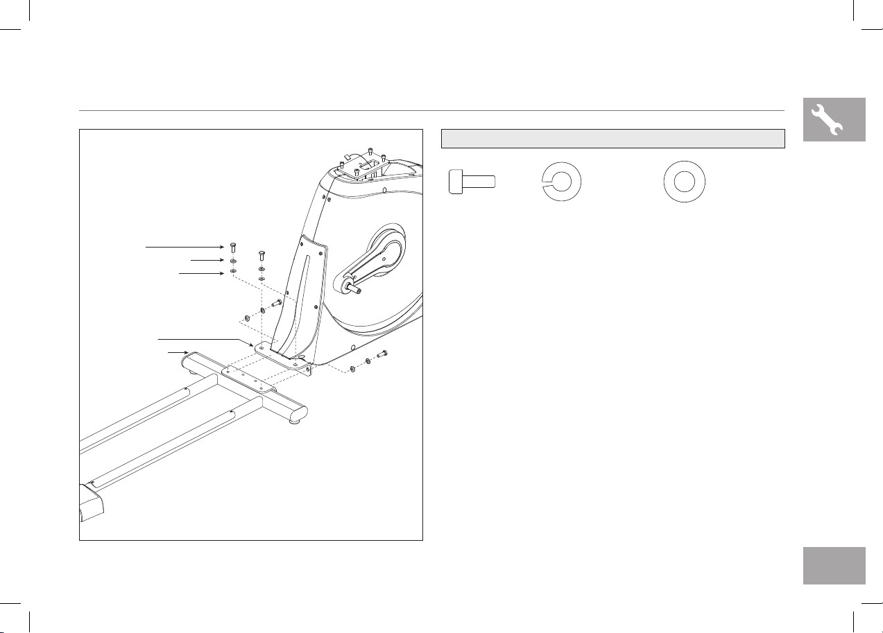
STABILIZER TUBE
POWER CORD SOCKET
MAIN FRAME
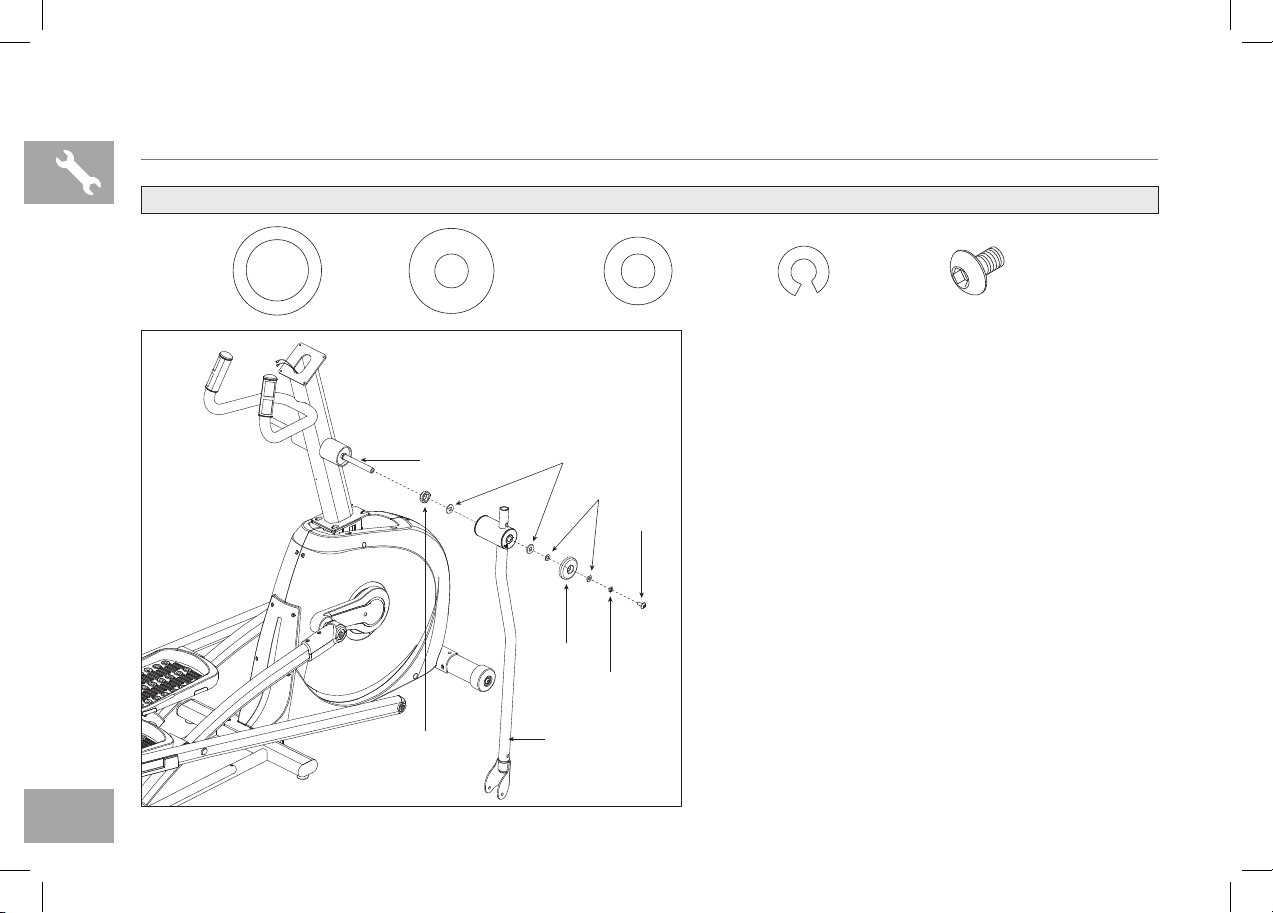
PEDAL ARM
REAR COVER
IPOD/MP3 PLAYER POCKET
CONSOLE FAN
CONSOLE MAST
TOUCH PAD PANEL AND DISPLAY WINDOWS
LOWER HANDLEBAR
LOWER LINK ARM
CAUTION AVERTISSEMENT PRECAUCIÓN
KEEP HANDS AND FEET
AWAY FROM THIS AREA.
GARDER LES MAINS ET LES
PIEDS LOIN DE CETTE REGION.
MANTENGA LAS MANOS Y LOS
PIES LEJOS DE ESTA AREA.