Epic 1000 Ex Elliptical User manual

Model No. EPEL4255.1
Serial No.
CAUT ON
Read all precautions and instruc-
tions in this manual before using
this equipment. Save this man-
ual for future reference.
Write the serial number in the space
above for future reference.
QUEST ONS?
As a manufacturer, we are com-
mitted to providing complete
customer satisfaction. f you
have questions, or if parts are
damaged or missing, PLEASE
CONTACT OUR CUSTOMER
SERV CE DEPARTMENT
D RECTLY.
CALL TOLL-FREE:
1-866-997-6999
Mon.–Fri., 6 a.m.–6 p.m. MST
ON THE WEB:
www.iconservice.com
USER'S MANUAL
Serial
Number
Decal

IMPORTANTPRECAUTIONS .................................................................3
BEFOREYOUBEGIN .......................................................................4
ASSEMBLY ...............................................................................5
OWTOOPERATET EELLIPTICALEXERCISER ..............................................10
MAINTENANCEANDTROUBLES OOTING ....................................................18
EXERCISEGUIDELINES ...................................................................19
PARTLIST ...............................................................................20
EXPLODEDDRAWING .....................................................................21
OWTOORDERREPLACEMENTPARTS ...........................................BACKCOVER
LIMITEDWARRANTY ............................................................BACKCOVER
2
TABLE OF CONTENTS

3
1. Read all instructions in this manual and all
warnings on the elliptical exerciser before
using the elliptical exerciser.
2. t is the responsibility of the owner to ensure
that all users of the elliptical exerciser are
adequately informed of all precautions.
3. Use the elliptical exerciser only as described
in this manual.
4. The elliptical exerciser is intended for home
use only. Do not use the elliptical exerciser in
a commercial, rental, or institutional setting.
5. Keep the elliptical exerciser indoors, away
from moisture and dust. Place the elliptical
exerciser on a level surface, with a mat be-
neath it to protect the floor or carpet. Make
sure that there is enough clearance around
the elliptical exerciser to mount, dismount,
and use it.
6. nspect and properly tighten all parts regu-
larly. Replace any worn parts immediately.
7. Keep children under age 12 and pets away
from the elliptical exerciser at all times.
8. The elliptical exerciser should not be used by
persons weighing more than 350 pounds.
9. Always hold the handlebars when mounting,
dismounting, or using the elliptical exerciser.
10. Keep your back straight when using the ellip-
tical exerciser; do not arch your back.
11. f you feel pain or dizziness while exercising,
stop immediately and begin cooling down.
12. Wear appropriate exercise clothes and ath-
letic shoes while using the elliptical exer-
ciser.
13. The pulse sensor is not a medical device.
Various factors, including the user's move-
ment, may affect the accuracy of heart rate
readings. The pulse sensor is intended only
as an exercise aid in determining heart rate
trends in general.
14. When you stop exercising, allow the pedals
to slowly come to a complete stop. The ellip-
tical exerciser does not have a free wheel;
the pedals will continue to move until the fly-
wheel stops.
15. The battery pack contains materials that are
considered hazardous to the environment.
Proper disposal of the battery is required by
federal law.
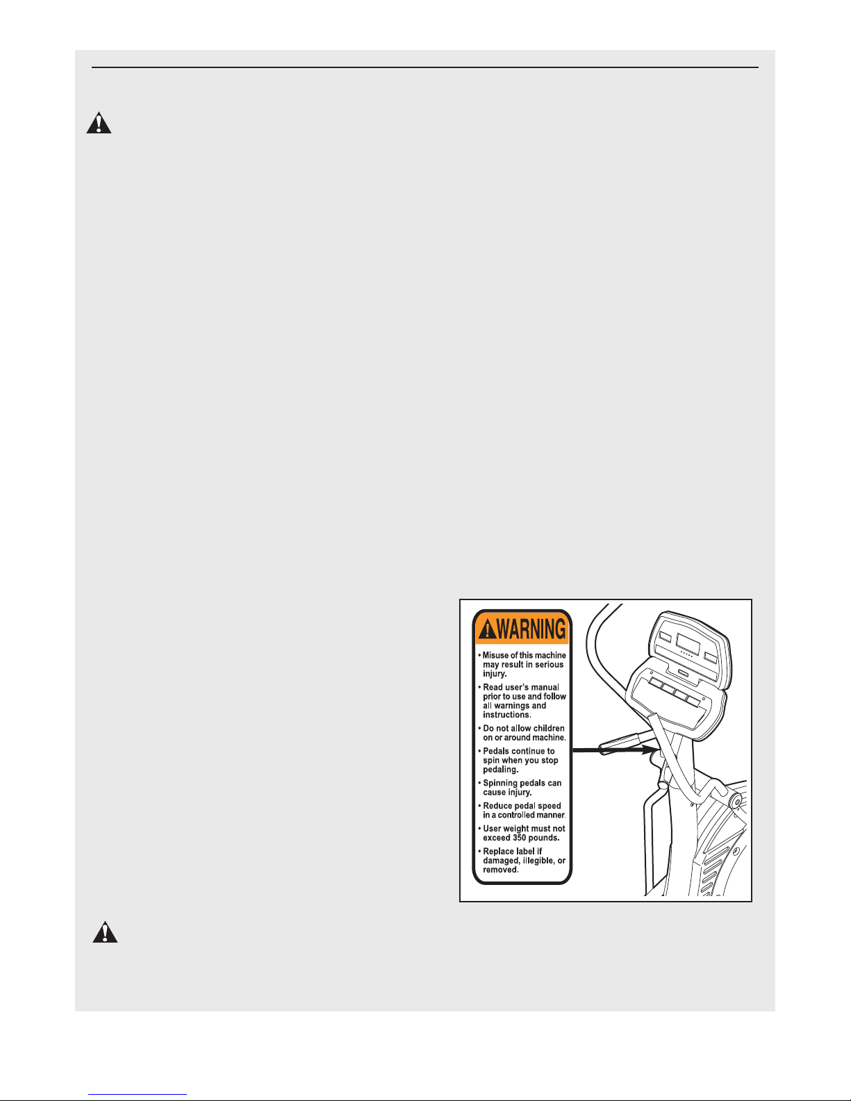
16. The decal shown below has been placed on
the elliptical exerciser. f the decal is missing
or illegible, call the toll-free telephone num-
ber on the front cover of this manual and
order a free replacement decal. Apply the
decal in the location shown.
WARN NG: Before beginning this or any exercise program, consult your physician. This
is especially important for persons over the age of 35 or persons with pre-existing health problems.
Read all instructions before using. CON assumes no responsibility for personal injury or property
damage sustained by or through the use of this product.
MPORTANT PRECAUT ONS
WARN NG: To reduce the risk of serious injury, read the following important precau-
tions before using the elliptical exerciser.

4
Congratulations for selecting the new EPIC™EX 1000
COMMERCIAL PRO elliptical exerciser. The EX 1000
elliptical exerciser is an incredibly smooth exerciser
that moves your feet in a natural elliptical path, mini-
mizing the impact on your knees and ankles. And the
EX 1000 elliptical exerciser offers an array of features
designed to help you achieve your fitness goals in the
convenience and privacy of your home.
For your benefit, read this manual carefully before
you use the elliptical exerciser. If you have ques-
tions after reading this manual, please call the toll-free
telephone number on the front cover of this manual. To
help us assist you, please note the product model
number and serial number before calling. The model
number is EPEL4255.1. The serial number can be
found on a decal attached to the elliptical exerciser
(see the front cover of this manual for the location of
the decal).
To avoid a registration fee for any service needed
under warranty, you must register the elliptical ex-
erciser at www.iconservice.com/registration.
Before reading further, please familiarize yourself with
the parts that are labeled in the drawing below.
andlebar
Console
Levelling Foot
Levelling Foot
andgrip Pulse Sensor
Water Bottle older*
*No water bottle is included
Wheel
Pedal
andle
BEFORE YOU BEG N

5
M8 Nylon
Locknut (72)–4
M4 x 19mm
Screw (57)–2
M10 Split
Washer (85)–20
M10 Washer
(67)–14
M8 Small
Washer (18)–4
M8 Washer
(69)–4
M8 x 55mm Bolt
Set (92)–2
M10 x 116mm Carriage Bolt (38)–2
M8 x 38mm Button
Screw (58)–4
Wave Washer
(88)–4
M10 x 123mm Button Screw (87)–2
M10 Nylon
Locknut (70)–2
M4 x 16mm
Screw (47)–6
Thrust Washer
(66)–4
M10 x 13mm Button
Screw (54)–14
M10 x 65mm Bolt
Set (94)–2
M8 x 19mm Button
Screw (56)–4
M10 x 25mm Patch
Screw (48)–4
To hire an authorized service technician to assemble the elliptical exerciser, call toll-free 1-800-445-2480.
Assembly requires two persons. Set the elliptical exerciser in a cleared area and remove all packing materials.
Do not dispose of the packing materials until assembly is completed. Assembly can be completed using the in-
cluded hex keys and your own adjustable wrench .
Use the drawings below to identify the small parts used for assembly. The number in parentheses below each
drawing is the key number of the part, from the PART LIST on page 20. The number following the key number is
the quantity needed for assembly. Note: Some small parts may have been preassembled. f a part is not in
the parts bag, check to see if it has been preassembled.
ASSEMBLY

6
1. Attach the Stabilizer (8) to the Frame (1) with two
M10 x 116mm Carriage Bolts (38) and two M10
Nylon Locknuts (70).
2. ave another person hold the Upright (2) in the po-
sition shown. Connect the Upper Wire arness (77)
to the Lower Wire arness (78).
Attach the Upright (2) to the Frame (1) with four
M10 x 25mm Patch Screws (48) and four M10 Split
Washers (85). Make sure that no wires are
pinched between the Upright and the Frame.
1
1
2
48
85
78
2
1
70
38
8
77
85
48
85

7
3. Attach the Track Frame (4) to the Frame (1) with
two M10 x 123mm Button Screws (87) and two
M10 Split Washers (85). Finger tighten a Button
Screw into the lower hole first, and then finger
tighten a Button Screw into the upper hole. Then,
tighten both Button Screws. Note: This step may be
easier if you raise the Frame a few inches in the lo-
cation shown by the arrow at the right while you at-
tach the Track Frame.
4. Apply a small amount of the included grease to the
sides of two Wave Washers (88) and two Thrust
Washers (66).
Slide a Weld Spacer (89) onto the Left Crank Arm
(83). Next, identify the Left Track Arm (12), which
is marked with an “L.” Orient the Left Track Arm as
shown, and slide it onto the Left Crank Arm. Then,
slide a Wave Washer (88) onto the end of the Left
Crank Arm.
Slide an M8 Small Washer (97) and an Axle Cap
(41) onto an M8 x 19mm Button Screw (56). Next,
fit a Thrust Washer (66) onto the shoulder of the
Axle Cap. Then, tighten the Button Screw into the
end of the Left Crank Arm (83). Make sure that
the Thrust Washer remains on the shoulder of
the Axle Cap, and that the Wave Washer (88)
remains on the end of the Left Crank Arm.
Repeat this step to attach the Right Track Arm
(11) to the right side of the elliptical exerciser.
11
4
83
85
4
1
87
85
87
89
88
41
56
12
18
66
5. Attach a Pedal (21) to the Left Pedal Leg (14) with
seven M10 x 13mm Button Screws (54), seven
M10 Split Washers (85), and seven M10 Washers
(67).
Attach the other Pedal (not shown) to the Right
Pedal Leg (not shown) in the same way.
5
21
67
67
85
85
54 54
14
3

6. Apply a thin film of grease to the barrel of an M10 x
65mm Bolt Set (94). Next, fit the bracket on the
Left Pedal Leg (14) onto the bracket on the Left
Track Arm (12). Attach the Left Pedal Leg to the
Left Track Arm with the Bolt Set.
Attach the Right Pedal Leg (not shown) to the
Right Track Arm (not shown) in the same way.
12
7
94
Grease
14
94
8. Apply a small amount of grease to the sides of two
Wave Washers (88) and two Thrust Washers (66).
Slide the Left andlebar (19) onto the andlebar
Axle (16) as shown. Then, slide a Wave Washer
(88) onto the end of the andlebar Axle.
Slide an M8 Small Washer (18) and an Axle Cap
(41) onto an M8 x 19mm Button Screw (56). Next,
fit a Thrust Washer (66) onto the shoulder of the
Axle Cap. Then, tighten the Button Screw into the
end of the andlebar Axle (16). Make sure that
the Thrust Washer remains on the shoulder of
the Axle Cap, and that the Wave Washer (88)
remains on the end of the Handlebar Axle.
Assemble the Right andlebar (20) in the same
way. Then tighten both M8 x 19mm Button Screws
(56) at the same time.
8
1
56
18
56
41
41
88
88
16
20
66
18
19
66
6
8
7. Identify the Left andlebar (19), which is marked
with an “L.” Insert the Left andlebar into one of
the andlebar Legs (17). Next, turn the Left
Handlebar and the Handlebar Leg so that the
wide side of the pivot tube on the Left
Handlebar is above the hexagonal holes in the
Handlebar Leg. Attach the Left andlebar with two
M8 x 38mm Button Bolts (58) and two M8 Nylon
Locknuts (72). Make sure that the Nylon
Locknuts are inside of the hexagonal holes. Do
not tighten the Button Bolts yet.
Assemble the Right andlebar (20) and the other
andlebar Leg (17) in the same way.
19 20
58 58
72
17 17
exagonal
oles
Wide side of
pivot tube

9
9. Apply a film of grease to the barrel of an M8 x 55mm
Bolt Set (92) and to a 7mm Spacer (55). Slide an
M8 Washer (69) and the Spacer onto the barrel.
While another person holds the front end of the
Left Pedal Leg (14) inside of the bracket on the left
andlebar Leg (17), insert the barrel of the Bolt
Set (92) through both parts. Next, slide a 7mm
Spacer (55) and an M8 Washer (69) onto the end
of the barrel of the Bolt Set. Then, turn the screw
of the Bolt Set a few turns into the barrel. Do not
overtighten the Bolt Set; the left Handlebar Leg
must be able to pivot freely.
Attach the right andlebar Leg (not shown) to the
Right Pedal Leg (not shown) in the same way.
See step 7. Tighten the four M8 x 38mm Button
Screws (58).
10.While another person holds the Display Console
(74) and the Control Console (75) near the Upright
(2), connect the Pulse Jumper Wire (76) to the con-
sole pulse wire, and the Upper Wire arness (77)
to the console wire harness. Insert the excess wires
into the Upright.
Set the Consoles (74, 75) on the Upright (2). Attach
the Consoles with six M4 x 16mm Screws (47).
Make sure that no wires are pinched. Do not
tighten the Screws yet.
14
9
10
2
92
17 92
55
55 69
69
47
47 77
76
75
74
11.Attach the Water Bottle older (26) to the Upright
(2) with two M4 x 19mm Screws (57).
See step 10. Tighten the six M4 x 16mm Screws
(47).
11
2
Grease
26
57
12. Make sure that all parts of the elliptical exerciser are properly tightened. Cover the floor beneath the el-
liptical exerciser to protect the floor from damage. Note: Some extra hardware may be left over.

10
HOW TO MOVE AND LEVEL THE ELL PT CAL
EXERC SER
Due to the size and weight of the elliptical exer-
ciser, moving it requires two persons. With the help
of another person, lift the handle on the rear of the el-
liptical exerciser until the elliptical exerciser will roll on
the front wheels. Carefully move the elliptical exerciser
to the desired location and then lower it.
CAUT ON: To decrease the risk of injury, bend your
legs and keep your back straight. Make sure to use
your legs rather than your back to lift the elliptical
exerciser. Do not attempt to move the elliptical exer-
ciser over an uneven surface.
If the elliptical exerciser rocks slightly on your floor, see
the inset drawings and turn the levelling feet under the
front and rear of the elliptical exerciser until the rocking
motion is eliminated.
EXERC S NG ON THE ELL PT CAL EXERC SER
To mount the elliptical exerciser, hold the handlebars
and step onto the pedal that is in the lowest position.
Next, step onto the other pedal. Push the pedals until
they begin to move with a continuous motion.
To dismount the elliptical exerciser, wait until the ped-
als come to a complete stop. The elliptical exerciser
does not have a free wheel; the pedals will con-
tinue to move until the flywheel stops. When the
pedals are stationary, step off the highest pedal first.
Then, step off the lowest pedal.
Lift
ere
Wheel
Levelling
Feet
Levelling
Foot
HOW TO OPERATE THE ELL PT CAL EXERC SER

11
FEATURES OF THE CONSOLE
The advanced console offers a selection of features
designed to make your workouts more effective. When
the manual mode of the console is selected, the resis-
tance of the pedals can be changed with the touch of a
button. As you pedal, the console will provide continu-
ous exercise feedback. You can even measure your
heart rate using the built-in handgrip pulse sensor.
The console also features personal goal programming
that allows you to choose a goal for your workout. As
you exercise, the console will display feedback until the
goal is reached.
In addition, the console offers nine preset programs.
Each program automatically changes the resistance of
the pedals and prompts you to increase or decrease
your pace as it guides you through an effective workout.
You can even create your own custom workout pro-
grams and save them in memory for future use.
The console also features three heart rate programs
that automatically change the resistance of the pedals
to keep your heart rate near a target heart rate as you
exercise.
To use the manual mode of the console, see page
12. To create and use a custom program, see page
14. To use a preset program, see page 15. To use a
heart rate program, see page 16.
D AGRAM OF THE CONSOLE

12
HOW TO USE THE MANUAL MODE
Begin pedaling to activate the console.
The elliptical exerciser requires no batteries or
external power source. Power is supplied by a
generator while you are pedaling. To activate
the console, begin pedaling at a moderate pace.
After a few seconds, the console displays will
light. A tone will then sound and the console will
be ready for use.
Select the manual mode.
When the power is
turned on, the
manual mode will
be selected and a
track will appear in
the display. If you
have selected a
program, reselect the manual mode by pressing
the Manual button.
Set a workout goal if desired.
If you do not wish to set a workout goal, go to
step 4.
To set a time, distance, or calorie goal for your
workout, press the increase and decrease buttons
below the Time, Distance, or Calories display. To
set a goal quickly, hold down the increase and de-
crease buttons. You can set one goal for each
workout.
For example, if
you plan to exer-
cise for 30 min-
utes, press the in-
crease and de-
crease buttons
below the Time
display until the display shows a goal of “30:00.”
Note: To set a pulse goal, see OW TO USE A
EART RATE PROGRAM on page 16.
Begin pedaling and change the resistance of
the pedals as desired.
As you pedal, change the resistance of the pedals
by pressing the Quick Resistance buttons if de-
sired. Note: After the Quick Resistance buttons
are pressed, it will take a moment for the pedals
to reach the selected resistance level.
Monitor your progress with the displays.
The matrix—When
the manual mode is
selected, the matrix
will show a track
representing 1/4
mile. As you exer-
cise, the indicators
around the track will light in succession until the
entire track is lit. The track will then darken and
the indicators will again begin to light in succes-
sion.
The Resistance
display—This dis-
play will show the
resistance level of
the pedals.
The Speed
display—This dis-
play will show your
pedaling speed, in
revolutions per
minute.
The Time
display—If no time
goal was set, this
display will show
the elapsed time. If
a time goal was
set, the display will
show the time remaining in your workout. Note:
When a program is selected (except for the first
heart rate program), the display will show the time
remaining in the program.
The Distance dis-
play—If no dis-
tance goal was set,
this display will
show the distance
that you have ped-
aled, in total revolu-
tions. If a distance goal was set, the display will
show the distance still to be pedaled during your
workout.
1
3
4
5
2

13
The Calories dis-
play—If no calorie
goal was set, this
display will show
the approximate
number of calories
you have burned.
If a calories goal was set, the display will show the
number of calories still to be burned during your
workout.
The Pulse dis-
play—This display
will show your
heart rate when
you use the hand-
grip pulse sensor
(see step 6
below).
Note: You can se-
lect any of three
backlight modes
for the displays.
The “On” mode
keeps the back-
light on while the
console is on. The “Off” mode turns the backlight
off. The “Auto” mode keeps the backlight on only
while you are exercising. To change the backlight
mode, first hold down the Start button for a few
seconds. The current backlight mode will appear in
the Calories display. Next, press the Quick
Resistance 1 button to change the backlight mode.
Then, press the Start button.
Measure your heart rate if desired.
f there are sheets of clear plastic on the metal
contacts on the handgrip pulse sensor, peel
off the plastic.
Place your
hands on the
handgrip pulse
sensor, with
your palms on
the contacts.
Avoid moving
your hands.
When your pulse is detected, one or two dashes
will appear in the Pulse display and then your
heart rate will be shown.
For the most accurate heart rate reading, continue
to hold the handgrips for about 30 seconds.
If your heart rate is not shown, make sure that your
hands are positioned as described. Avoid moving
your hands excessively or squeezing the metal
contacts too tightly. For optimal performance, peri-
odically clean the metal contacts using a soft
cloth; never use alcohol, abrasives, or chemi-
cals.
When you are finished exercising, the console
will automatically turn off.
If the pedals are not moved for a few seconds, a
series of tones will sound, the Time display will
begin to flash, and the console will pause.
If the pedals are not moved for a few minutes, the
console will turn off and the displays will be reset.
6
7
Contacts

14
Turn on the console.
See step 1 on page 12.
Select a custom program.
To select a custom
program, press one
of the three Custom
buttons. When a
Custom button is
pressed, the indica-
tor on the button
will light.
Note: f the custom program has not yet been
defined, see step 3 to create the program. f
the program is already defined, see step 4 to
use the program.
Press the Start button or begin pedaling to
start the program.
Refer to the matrix.
Each custom pro-
gram is divided into
40 one-minute seg-
ments. One resis-
tance setting and
one pace setting
can be programmed for each segment. The resis-
tance setting for the first segment will be shown in
the flashing Current Segment column of the ma-
trix. (The pace settings are not shown in the ma-
trix.) To program a resistance setting and a pace
setting for the first segment, simply adjust the re-
sistance of the pedals as desired by pressing the
Quick Resistance buttons and pedal at the de-
sired pace.
When the first segment of the program ends, a se-
ries of tones will sound and the current resistance
setting and the current pace setting will be saved
in memory. The columns of indicators will then
move one column to the left, and the resistance
setting for the second segment will be shown in
the flashing Current Segment column. Program a
resistance setting and a pace setting for the sec-
ond segment as described above.
Continue programming resistance and pace set-
tings for as many segments as desired; custom
programs can have up to 40 segments.
Press the Start button or begin pedaling to
start the program.
The custom program will function in almost the
same way as a preset program (see steps 3 and 4
on page 15).
If desired, you can redefine the program while
using it. To change the resistance or pace set-
ting for the current segment, simply press the
Quick Resistance buttons or change your pedaling
pace. When the current segment ends, the new
setting will be saved in memory.
Monitor your progress with the displays.
See step 5 on page 12.
Measure your heart rate if desired.
See step 6 on page 13.
When you are finished exercising, the console
will automatically turn off.
See step 7 on page 13.
7
6
5
4
3
2
1
HOW TO CREATE AND USE A CUSTOM
PROGRAM
Current Segment

15
HOW TO USE A PRESET PROGRAM
Turn on the console.
See step 1 on page 12.
Select a preset program.
To select a preset
program, press
one of the Aerobic,
Performance, or
Endurance but-
tons. When an
Aerobic,
Performance, or Endurance button is pressed, the
indicator on the button will light. When a preset
program is selected, a profile of the first several
resistance settings of the program will appear in
the matrix, the program time will appear in the
Time display, the maximum resistance setting of
the program will flash in the Resistance display,
and the maximum speed setting of the program
will flash in the Speed display for a few seconds.
Press the Start button or begin pedaling to
start the program.
Each program is divided into either 20 or 30 one-
minute segments. One resistance setting and one
pace setting are programmed for each segment.
Note: The same resistance setting and/or target
pace may be programmed for two or more consec-
utive segments.
When you start the
program, the resis-
tance setting for
the first segment
will be shown in
the flashing
Current Segment
column of the matrix. The resistance settings for
the next several segments will be shown in the
columns to the right.
When only three seconds remain in the first seg-
ment of the program, both the Current Segment
column and the column to the right will flash, a se-
ries of tones will sound, and the time will flash in
the Time display. When the first segment ends, all
resistance settings will move one column to the
left. The resistance setting for the second seg-
ment will then be shown in the flashing Current
Segment column and the resistance of the pedals
will automatically change to the resistance setting
for the second segment.
The program will continue until no time remains in
the Time display.
Use the pace guide to pace your exercise.
Throughout the program, the pace guide will
prompt you to increase or decrease your pedaling
pace. When one of the “Too Slow” indicators
lights, increase your pace; when one of the “Too
Fast” indicators lights, decrease your pace. When
the center indicator lights, maintain your current
pace.
mportant: The pace guide is intended only to
provide a goal. Make sure to pedal at a pace
that is comfortable for you.
If you stop pedaling for several seconds, a tone
will sound and the program will pause. To restart
the program, simply resume pedaling.
Monitor your progress with the displays.
See step 5 on page 12.
Measure your heart rate if desired.
See step 6 on page 13.
When you are finished exercising, the console
will automatically turn off.
See step 7 on page 13.
7
3
2
1
6
5
4
Current Segment

16
HOW TO USE A HEART RATE PROGRAM
Turn on the console.
See step 1 on page 12.
Select a heart rate program.
To select a heart
rate program,
press one of the
three eart Rate
buttons. When a
eart Rate button
is pressed, the in-
dicator on the button will light.
f the first heart
rate program is
selected, a pulse
symbol will appear
in the matrix.
f the second or
third heart rate
program is se-
lected, a profile of
the first several
target heart rate
settings of the pro-
gram will appear in the matrix.
Enter a target heart rate setting.
f the first heart rate program is selected, the
target heart rate setting for the program will flash
in the Pulse display. If desired, press the increase
and decrease buttons below the Pulse display to
change the target heart rate setting (see EXER-
C SE NTENS TY on page 19). Note: The same
target heart rate setting will be programmed for all
segments.
f the second or third heart rate program is se-
lected, the maximum target heart rate setting of
the program will flash in the Pulse display. If de-
sired, press the increase and decrease buttons
below the Pulse display to change the maximum
target heart rate setting (see EXERC SE NTEN-
S TY on page 19). Note: If the maximum target
heart rate setting is changed, the intensity level of
the entire program will change.
Hold the handgrip pulse sensor.
To use a heart rate program, you must use the
handgrip pulse sensor (see step 6 on page 13). It
is not necessary to hold the handgrips continu-
ously during the program. owever, you should
hold the handgrips frequently for the program to
operate properly. Each time you hold the hand-
grips, keep your hands on the metal contacts
for at least 30 seconds. Note: When you are not
holding the handgrips, the letters “PLS” will flash
in the Pulse display instead of your heart rate.
Press the Start button to start the program.
The first heart rate program—This program is
divided into 100 one-minute segments. The same
target heart rate setting is programmed for all
segments. Note: For a shorter workout, stop exer-
cising or select a different program before the pro-
gram ends.
The second and third heart rate programs—
These programs are divided into 30 one-minute
segments. One target heart rate setting is pro-
grammed for each segment. Note: The same tar-
get heart rate setting may be programmed for two
or more consecutive segments.
The target heart
rate setting for the
first segment will
be shown in the
flashing Current
Segment column of
the matrix. The tar-
get heart rate settings for the next several seg-
ments will be shown in the columns to the right.
When only three seconds remain in the first seg-
ment of the program, both the Current Segment
column and the column to the right will flash, a se-
ries of tones will sound, and all target heart rate
settings will move one column to the left. The tar-
get heart rate setting for the second segment will
then be shown in the flashing Current Segment
column.
5
4
1
3
2
Current Segment

17
Both heart rate programs—As you pedal, the
console will regularly compare your heart rate to
the target heart rate setting. If your heart rate is
too far below or above the target heart rate set-
ting, the resistance of the pedals will automatically
increase or decrease to bring your heart rate
closer to the target heart rate setting.
After the first segment ends, the pace guide will
prompt you to maintain a constant pedaling pace.
When one of the “Too Slow” indicators lights, in-
crease your pace; when one of the “Too Fast” in-
dicators lights, decrease your pace. When the
center indicator lights, maintain your current pace.
mportant: The target heart rate settings are
intended only to provide motivation. Make
sure to exercise at a pace that is comfortable
for you.
Note: During the program, you can manually over-
ride the resistance setting for the current seg-
ment, if desired, with the Quick Resistance but-
tons. owever, when the console compares your
heart rate to the target heart rate setting, the re-
sistance of the pedals may automatically increase
or decrease to bring your heart rate closer to the
target heart rate setting.
If you stop pedaling for several seconds, a tone
will sound and the program will pause. To restart
the program, simply resume pedaling.
Monitor your progress with the displays.
See step 5 on page 12.
When the program is finished, the console will
automatically turn off.
See step 7 on page 13.
7
6

18
Most problems can be solved by following the simple steps below. Find the symptom that applies, and fol-
low the steps listed. f further assistance is needed, please see the front cover of this manual.
WEEKLY MA NTENANCE
Inspect and properly tighten all external parts of the el-
liptical exerciser. Clean the elliptical exerciser with a
small amount of mild multi-purpose cleaner applied to
a 100% cotton cloth. When cleaning the elliptical exer-
ciser, pay special attention to the track and wheels.
Remove all debris from the track. Clean the pedal cov-
ers with a soft nylon brush. Do not use acidic clean-
ers—doing so will void your warranty. Never spray
any cleaner directly onto the elliptical exerciser.
TROUBLESHOOT NG
1. SYMPTOM: THE ELL PT CAL EXERC SER S
NOT LEVEL
If the elliptical exerciser rocks slightly during use, see
OW TO MOVE AND LEVEL T E ELLIPTICAL EX-
ERCISER on page 10.
2. SYMPTOM: THE PULSE SENSOR DOES NOT
FUNCT ON PROPERLY
If the handgrip pulse sensor does not function properly,
see step 6 on page 13.
3. SYMPTOM: THE PEDAL D SKS RUB AGA NST
THE S DE SH ELDS
If a pedal disk rubs against a side shield, loosen the
side shield mounting screws and move the side shield
slightly until the pedal disk stops rubbing. Then,
retighten the side shield mounting screws.
4. SYMPTOM: THE PEDAL WHEELS SQUEAK
If the pedal wheels squeak, use a 100% cotton cloth to
remove debris from the track and the wheels. If the
pedal wheels continue to squeak, apply a light coat of
silicone-based lubricant to the track.
5. SYMPTOM: THE CONSOLE TURNS OFF AS
SOON AS YOU STOP PEDAL NG
If the console turns off as soon as you stop pedaling,
the battery pack may not be fully charged. The longer
you pedal, the longer the battery pack will maintain a
charge. It may be necessary to pedal for a few minutes
to charge the battery pack each time you exercise. If
the console turns off as soon as you stop pedaling,
even after you have pedaled for several minutes, call
the toll-free telephone number on the front cover of this
manual immediately.
6. SYMPTOM: THE PEDALS SL P OR G VE ON THE
POWER STROKE OF EACH REVOLUT ON
If the pedals slip during the power stroke, the drive belt
is slipping. Follow the instructions below to adjust the
tension of the drive belt.
First, remove the two
M6 x 16mm Button
Screws (49) attaching
the left Pedal Disk (5).
Without removing the
Pedal Disk, pivot it out
of the way.
Next, locate the M10
Flange Nut (95). Turn
the Flange Nut clock-
wise until the pedals
no longer slip during
the power stroke.
Reattach the Pedal
Disk (5).
MA NTENANCE AND TROUBLESHOOT NG
49
5
95

19
The following guidelines will help you to plan your ex-
ercise program. Remember that proper nutrition and
adequate rest are essential for successful results.
EXERC SE NTENS TY
Whether your goal is to burn fat or to strengthen your
cardiovascular system, the key to achieving the de-
sired results is to exercise with the proper intensity.
The proper intensity level can be found by using your
heart rate as a guide. The chart below shows recom-
mended heart rates for fat burning, maximum fat burn-
ing, and cardiovascular (aerobic) exercise.
To find the proper heart rate for you, first find your age
near the bottom of the chart (ages are rounded off to
the nearest ten years). Next, find the three numbers
above your age. The three numbers are your “training
zone.” The lower two numbers are recommended
heart rates for fat burning; the highest number is the
recommended heart rate for aerobic exercise.
Fat Burning
To burn fat effectively, you must exercise at a rela-
tively low intensity level for a sustained period of time.
During the first few minutes of exercise, your body
uses easily accessible carbohydrate calories for en-
ergy. Only after the first few minutes of exercise does
your body begin to use stored fat calories for energy. If
your goal is to burn fat, adjust the intensity of your ex-
ercise until your heart rate is near the lowest number
in your training zone as you exercise.
For maximum fat burning, adjust the intensity of your
exercise until your heart rate is near the middle num-
ber in your training zone as you exercise.
Aerobic Exercise
If your goal is to strengthen your cardiovascular sys-
tem, your exercise must be “aerobic.” Aerobic exercise
is activity that requires large amounts of oxygen for
prolonged periods of time. This increases the demand
on the heart to pump blood to the muscles, and on the
lungs to oxygenate the blood. For aerobic exercise,
adjust the intensity of your exercise until your heart
rate is near the highest number in your training zone
as you exercise.
WORKOUT GU DEL NES
Each workout should include the following three parts:
A warm-up, consisting of 5 to 10 minutes of stretching
and light exercise. A proper warm-up increases your
body temperature, heart rate, and circulation in prepa-
ration for exercise.
Training zone exercise, consisting of 20 to 30 min-
utes of exercising with your heart rate in your training
zone. (During the first few weeks of your exercise
program, do not keep your heart rate in your training
zone for longer than 20 minutes.)
A cool-down, with 5 to 10 minutes of stretching. This
will increase the flexibility of your muscles and will
help to prevent post-exercise problems.
EXERC SE FREQUENCY
To maintain or improve your condition, complete three
workouts each week, with at least one day of rest be-
tween workouts. After a few months of regular exer-
cise, you may complete up to five workouts each week
if desired. The key to success is to make exercise a
regular and enjoyable part of your everyday life.
WARN NG:
Before beginning this or any exercise pro-
gram, consult your physician. This is espe-
cially important for persons over the age of 35
or persons with pre-existing health problems.
The pulse sensor is not a medical device.
Various factors, including the user's move-
ment, may affect the accuracy of heart rate
readings. The pulse sensor is intended only
as an exercise aid in determining heart rate
trends in general.
EXERC SE GU DEL NES

20
To locate the parts listed below, see the EXPLODED DRAWING on pages 21, 22, and 23.
11Frame
21 Upright
32Track
41Track Frame
52Pedal Disk
61Left Side Shield
71Right Side Shield
81Stabilizer
91Crank
10 1 Crank Spacer
11 1 Right Track Arm
12 1 Left Track Arm
13 1 Right Pedal Leg
14 1 Left Pedal Leg
15 1 Drive Belt
16 1 andlebar Axle
17 2 andlebar Leg
18 4 M8 Small Washer
19 1 Left andlebar
20 1 Right andlebar
21 2 Pedal
22 2 Transport Wheel
23 2 andlebar Foam
24 10 Plastic Insert
25 1 Pulley
26 1 Water Bottle older
27 4 6mm Spacer
28 2 Set Screw
29 1 Idler
30 1 Generator
31 4 Wheel
32 1 Control Board
33 2 Pulse Grip
34 10 Bearing Cradle
35 4 Endcap
36 4 Levelling Foot
37 4 M6 Split Washer
38 2 M10 x 116mm Carriage Bolt
39 2 andlebar Cap
40 4 Ramp Screw
41 4 Axle Cap
42 12 Bearing
43 1 Controller Bracket
44 1 Short Crank Spacer
45 2 Snap Ring
46 4 Wheel Bushing
47 8 M4 x 16mm Screw
48 4 M10 x 25mm Patch Screw
49 8 M6 x 16mm Button Screw
50 2 M8 x 56mm Button Screw
51 4 Crank Screw
52 8 Stand Off
53 2 M6 x 12mm Button Screw
54 14 M10 x 13mm Button Screw
55 4 7mm Spacer
56 4 M8 x 19mm Button Screw
57 2 M4 x 19mm Screw
58 4 M8 x 38mm Button Screw
59 20 M5 x 16mm Screw
60 4 16mm Spacer
61 2 M8 x 48mm Bolt
62 2 3mm Spacer
63 8 Pedal Bushing
64 4 Long Side Shield Spacer
65 2 Key
66 4 Thrust Washer
67 14 M10 Washer
68 1 Battery Pack
69 12 M8 Washer
70 2 M10 Nylon Locknut
71 1 Tension Bolt
72 11 M8 Nylon Locknut
73 1 Short Side Shield Spacer
74 1 Display Console
75 1 Control Console
76 1 Pulse Jumper Wire
77 1 Upper Wire arness
78 1 Lower Wire arness
79 1 Controller Wire arness
80 1 Ground Wire
81 1 Generator Coil Wire
82 1 Electromagnet Wire
83 1 Left Crank Arm
84 1 Right Crank Arm
85 20 M10 Split Washer
86 4 M8 Split Washer
87 2 M10 x 123mm Button Screw
88 4 Wave Washer
89 3 Weld Spacer
90 4 Small Bearing Cradle
91 12 Small Bearing
92 2 M8 x 55mm Bolt Set
93 2 Wheel Bolt
94 2 M10 x 65mm Bolt Set
95 1 M10 Flange Nut
96 4 M6 Washer
#1Userʼs Manual
#3 ex Key
#2Grease
Key No. Qty. Description Key No. Qty. Description
Note: # indicates a non-illustrated part. Specifications are subject to change without notice. See the back cover of
this manual for information about ordering replacement parts.
PART L ST—Model No. EPEL4255.1 R0509A
This manual suits for next models
1
Other Epic Elliptical Trainer manuals
Popular Elliptical Trainer manuals by other brands

True
True SPECTRUM ELLIPTICAL XS1000 owner's manual

Vision Fitness
Vision Fitness X6000 Assembly guide

SportsArt Fitness
SportsArt Fitness 8100 incline calibration guide

Keys Fitness
Keys Fitness Stepper Machine E2-0 owner's manual

True
True CS400 owner's manual

Precor
Precor Experience Sereis Getting started guide