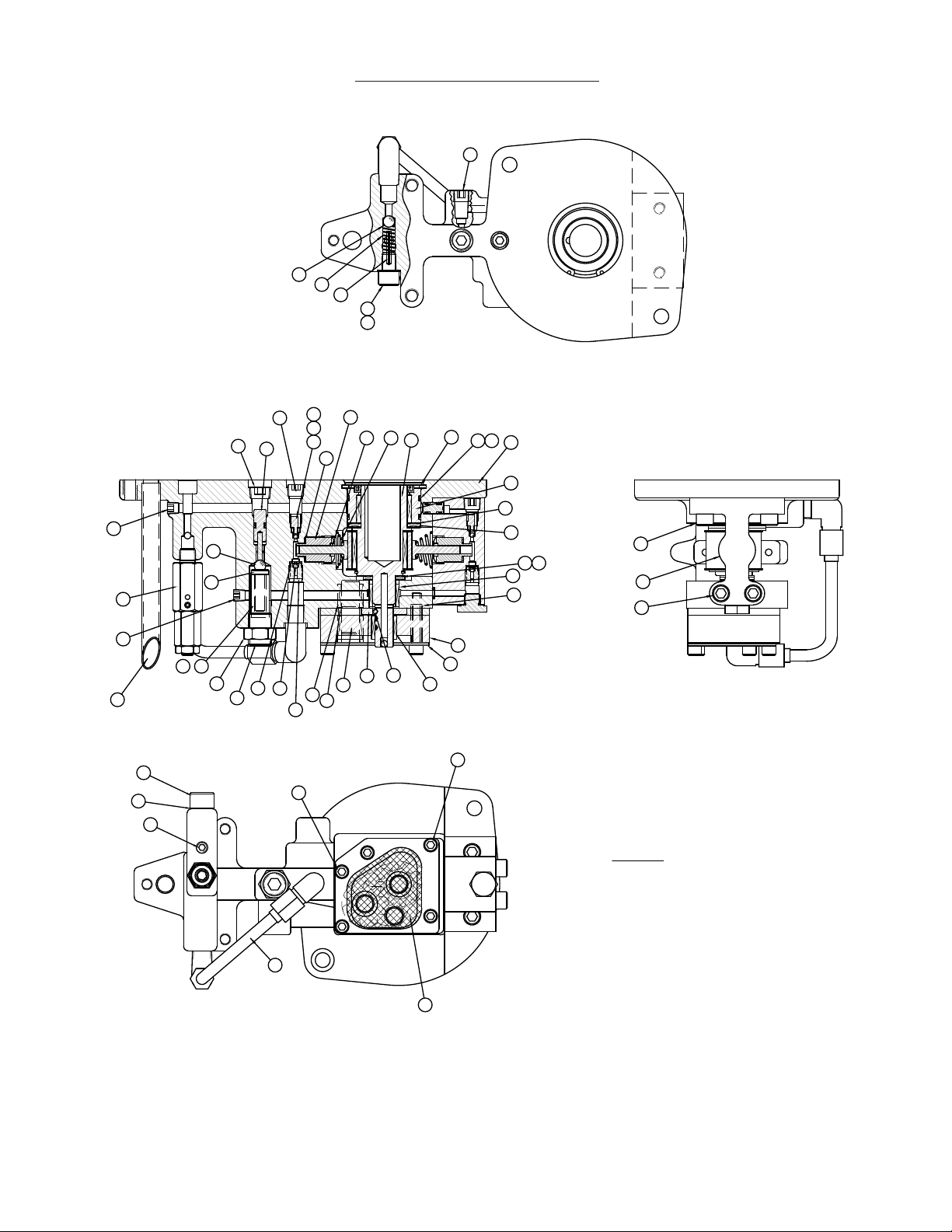
AFL 15GBM Installation and operation manual

MAILING / SHIPPING
104 Hidden Lake Circle
Spartangreen Business Park
Duncan, SC 29334
(800) 866-7385
PARTS OR SERVICE
Contact Simplex
(800) 323-9114
15GBM GASOLINE HYDRAULIC PUMP
REVISION: B - 0513
Part Sheet: 54195
OPERATING & MAINTENANCE INSTRUCTIONS

2
OPERATING INSTRUCTIONS AT A GLANCE
Before Operating Pump:
1. Use only cylinders , hoses and equipment rated at 10,000 psi.
2. Make sure all hose and tting connections are tight and secure. Hoses cannot be kinked or twisted.
3. Oil level should be 1”from the top of the reservoir plate, with tool retracted and motor o.
4. Never operate the pump in advance at 10,000 psi without tool movement for more than 1 minute.
Continuing to operate the pump without tool movement will overheat the oil.
After Completing the Job:
1. Before disconnecting hoses, ttings, etc, be sure the tool is retracted and unloaded, then unplug the power cord.
2. Store the pump in a clean, dry area.
Periodic Maintenance:
1. Completely change the hydraulic oil and clean the oil lter screen and magnet (located in the reservoir) twice a year.
(Use SIMPLEX oil only - Part #A01). Change the oil more frequently when used in extremely dusty areas or when the oil has
been overheated. Using oil other than the SIMPLEX brand, may void the pump warranty.
SECTION I
SAFETY
1-1.
Working Pressure
The pump’s maximum working pressure is 10,000 psi (700 kg/cm2). Make sure that all hydraulic equipment, hoses , etc. used with
this pump are rated at 10,000 psi operating pressure.
1-2.
Hydraulic Connections
Never disconnect or connect any hydraulic hoses or ttings without rst unloading the tool. Unplug the electrical cord of the
pump and open all hydraulic controls to ensure that the system has been depressurized. If the system includes a gauge, double
check the gauge ensure pressure has been released.
When making connections with quick disconnect couplings , make sure the couplings are fully engaged. Threaded connections
such as ttings , gauges , etc. mus t be securely tightened and leak free.
CAUTION: Loose or improperly threaded ttings can be potentially dangerous if pressurized, however, severe over
tightening can cause premature thread failure. Fittings need to be tightened secure & leak free. Never hold or stand
directly in line with any hydraulic connections while pressurizing. Never grab, touch or in any way come in contact with a
hydraulic pressure leak. Escaping oil can penetrate the skin and a serious injury can result.
Do not subject the hose to potential hazard such as sharp surfaces , extreme heat or heavy impact. Do not allow the hose to kink &
twist. Inspect each hose for wear before each use.

3
SECTION II
INSTRUCTIONS BEFORE USE
Read carefully. Most malfunctions in new equipment are the result of improper operation and/or improper set-up assembly.
Preparation: Remove pump from shipping container -- but do not remove any plugs or valves until the unit is ready to be fully
assembled to prevent dirt or foreign matter from contaminating system.
Inspection: Visually inspect all components for shipping damage. If any damage is found, notify carrier immediately.
2-1.
Gasoline, Oil and Fuel
1. Above 32 degrees Fahrenheit use S.A.E. 10 W 30 (Motor only)
2. Below 32 degrees Fahrenheit use S.A.E. 5 W 20 (Motor only)
3. Oil sump capacity - About 1.3 pints or check dip stick
4. Use clean, unleaded automotive gasoline (without alcohol)
2-2.
Hydraulic Connections:
Check hydraulic oil level to prevent possible pump burnout. Open the ll plug located at the top of the motor shroud. Remove
inspection plug on cover plate. Oil level should be approximately 1”from top of reservoir plate with tools retracted and motor o.
Add SIMPLEX oil as necessary. Do not mix dierent grades of oil.
Make sure all desired gauge, valve, hose and quick coupler connections are tight and secure before operating
(See Section 1-2). The pumps pressure ports is 3/8 NPTF and are located just below the control valve. (See Section 3-1).
These pumps are equipped with a“popper” internal relief valve that makes an audible popping noise when 10,000 psi hydraulic
pressure is reached.
The use of a pressure gauge is strongly recommended for normal operation of these pumps and required when the external
adjustable relief valve pressures are changed. Mounted on a gauge adapter between the pump and cylinder, the gauge permits
the operator to monitor tool operating pressures .
Do not exceed rated capacity of equipment connected to pump. Where shock loading or unsteady loads may cause overloading
of cylinders, the operator must use larger capacity cylinders to provide additional operating margin.
2-3.
Starting Instructions (Gasoline Engine)
Throttle to choke position ( extreme right ): Grasp STARTER HANDLE and pull rope out slowly to engagement: Pull rope with a
rapid, continuous full stroke and let rewind slowly, and do not allow to snap back. Move the control lever to “HIGH SPEED” position
then to“RUN”as the engine warms.

4
SECTION III
OPERATION
3-1.
Control Valves:
3-Way Valve for Single Acting Tools Pushing lever to right directs pump output to
right-hand port, To the tool. Pushing lever to left directs pump output to tank and allows
the tool to open or retract. Center position is neutral/hold. Pump output is directed back
to tank.
3-2.
Place valve in neutral/hold position (as described above) to prevent accidental tool
movement.Start the pump and let the pump idle for a few minutes.
3-3.
Bleeding the hydraulic system air can be removed from the system by fully operating and retracting the hydraulic tool several
times with the pump elevated so its reservoir is higher than the tool. Single-acting tools should be inverted. When the trapped air
is removed from the hydraulic circuit, the tool will advance and retract smoothly. Sluggish tool action is usually the rst sign of air
in the system.
3-4.
Press the pendant control switch to activate the tool. Releasing the switch automatically releases the tool.
3-5.
Never operate the pump at 10,000 psi without tool movement for more than 1 minute because this could overheat the oil.
SECTION IV
MAINTENANCE
4-1.
Maintain Oil Level -- check hydraulic oil level every 30 hours of operation. Add SIMPLEX hydraulic oil when necessary. Oil level
should be no more than 1”from top of reservoir plate with tool retracted and motor o.
Completely change oil at least twice a year. The following conditions require more frequent oil changes :
a. Rigorous duty, where oil temperature may reach 140 F .
b. High humidity environment and extreme changes in temperature that can result in condensation inside the reservoir.
c. Dirty or dusty environments may contaminate the oil.
4-2.
Clean Oil Filter screen Once a Year
a. Loosen and remove reservoir plate bolts . Lift pump unit o the reservoir, being careful not to damage the gasket.
b. Remove debris from screen with a tooth brush.
c. Blow dry and inspect, repeat cleaning as needed.
4-3. Keep areas around pump unobstructed to provide good air ow around the motor and pump. Keep the motor and pump as
clean as possible.
AB
HOLD ADV.
RET.

5
SECTION V
TROUBLESHOOTING
If the procedures listed below do not remedy the problem, the pump will require service and should be taken to an Authorized
SIMPLEX Service Center for repair.
PROBLEM CAUSE - SOLUTION
1. Air in the hydraulic system. See Sec. 3-3 for correct
bleeding procedure.
2. Check reservoir oil level.
1. Check manufacturers operating instructions.
1. Air in system. (See Sec. 3-3 for bleeding procedure).
2. Be sure the oil reservoir is lled to normal level.
3. Check all points where air might leak into system.
1. Oil viscosity too high. Replace with SIMPLEX oil.
2. Check for high pressure leakage at relief valve or plugs .
3. Oil level is low. Fill reservoir to normal level or ret pump
with larger reservoir.
1. Pump is not primed. Run pump a few minutes tipping
from side to side.
2. Internal leakage. Take to SIMPLEX Authorized Service
Center for repair.
3. Damaged O-Rings. Take to nearest Simplex Authorized
Service Center.
4. Defective control valve. (Troubleshoot separately).
Sporadic Tool Action
Engine Will Not Start
Noisy Operation
Pump Oil is Over Heating
Pump Runs but Will Not Pump Oil
or build full pressure

6
PUMP ASSEMBLY - 7630014
OIL
44779
DRAIN
tm
Black & Blue
Alcoa Conductor Accessories
t o o l s e r i e s
ALCOA
Mailing Address:
P.O.Box 3127
Spartanburg, sc 29304
Phone: 1-800-866-7385
Shipping Address:
260 ParkwayEast
Duncan, SC 29334
DATE CODE
10,000PSI/700BAR
SERIAL NO.
7630014
HOLD ADV.RET.
GASOLINE MOTOR POWER PUMP
INSTRUCTIONS FOR SAFE OPERATION
MOTOR OIL & FUEL
1. ABOVE 32° F USE S.A.E. 10W30 (MOTOR OIL)
BELOW 32° F USE S.A.E. 5W20 (MOTOR OIL)
OILSUMP CAPACITY -- ABOUT 1.3 PINTS
2. USE CLEAN, UNLEADEDAUTOMOTIVE GASOLINE. (DO NOT USE GASOLINE CONTAINING ALCOHOL).
STARTING:
1. POSITION CONTROL VALVETO THE NEUTRAL (CENTER) POSITION.
2. IF THE ENGINE IS COLD, MOVETHE THROTTLE TO THE CHOKE POSITION (ALL THE WAYTO THE
EXTREME RIGHT). AS SOO AS THE MOTOR IS RUNNING, MOVE THE THOROTTLE BACK 1" TO THE
RUN POSITION.
OPETATINGTHE PUMP
1. USE ONLYCYLINDERS, HOSES AND RELATED EQUIPMENT RATED@10,000 PSI.
2. MAKE SUREALL HOSE AND FITTING CONNECTIONS ARE TIGHT AND SECURE. HOSES CANNOTBE
KINKED OR TWISTED.
3. CHECK THE RESEVOIR OILLEVEL. FILL TO ONE OR TWO INCHES FROM THE TOP IF NECESSARY.
DO NOT
USE MOTOR OILIN THE HYDRAULIC RESERVOIR.
4. NEVER OPERATETHE PUMP WITHOUT RAM MOVEMENT FOR MOTE THAN I MINUTE WITHOUT SHIFTING
THE CONTROLVALVE TO NEUTRAL (CENTER). LEAVINGTHE VALVE IN THEADVANCE OR RETRACT
POSITION WITHOUTTHE ROD MOVING WILL OVERHEAT THE OIL.
AFTER COMPLETING THE JOB
1. BEFORE DISCONNECTING HOSES, FITTINGS, ETC., FIRST BE SURETHE RAM IS UNLOADED AND THE
PUMP MOTOROFF. THEN SHIFT ALL HYDRAULIC CONTROLS SEVERALTIMES TO RELEASE SYSTEM
PRESSURE.
PERIODIC MAINTENANCE
1. COMPLETELYCHANGE THE HYDRAULIC OIL AND CLEAN THE OIL FILTERSCREEN AND MAGNET (LOCATED
IN THE RESERVOIR)TWICE A YEAR. CHANGE THE OIL MORE FREQUENTLYWHEN USED IN EXTREMELY
DUSTYAREAS OR WHEN THE OIL HAS BEEN OVERHEATED.
44815
2
PUMP ASSEMBLY 7630014
TORQUE TO
250 IN*LBS
8
TORQUE TO
100 IN*LBS
10
16
4
11
15
47
46
49
1
TORQUE TO
250 IN*LBS
42
43
7
23
17
3
44
41
56
14
13
19
ATTACH WITH LOCTITE
454 OR EQUIVALENT 45

7
PUMP ASSEMBLY - 7630014
Item # Part # Name Qty.
44278 FUNNEL 1
1AO1 HYD OIL-1 GAL. 2
244912SS PUMP ASM W/PV 3.75GA 1
369285BSS 2 GAL RESVR. ALCOA 1
466014 GASKET 1
568000 BREATHER VENT BF-4 1
687492 HEX STL PIPE PLUG 1/4 NPTF 1
768571SS FILLER PLUG 2
869249 SCREW 1/4-20 X 3/4 S.T. 12
10 44823Z ALCOA DECAL 2
11 44815 GEN SAFE USE GAS LBL 1
13 44422SS 4 WAY MAN ASM W/REL 1
14 69242 VALVE GASKET 1
15 93599 SHCS 3/8-16 X 2 1/2 3
16 69378SS VAL ADP W/ CHECK ASM 1
17 87145 PLUG 1
19 45643SS 4W VALVE ASM. MANUAL 1
23 68069 LABEL, POSITION 1
41 66238 HANDLE 2 GALLON 1
42 CR215 DUST CAP 1
43 40858 FEMALE COUPLER 3050-3 1
44 69479 RUBBERFOOT VBM-3005 4
45 44735 POWER PUMP METAL TAG 1
46 44779 LEVEL GAUGE DECAL 1
47 69284 GAGE LIQUID LEVEL 1
49 68917 PIPE NIPPLE 1/8 NPT 1

8
SUB PUMP ASSEMBLY - 44910SS
21
35
36
37
38
46
53
54
55
1
2
3
5
6
4
8
9
10
12 13
14
16
15
17
21
22
23
24
38
41
25
7
31
42
18
45
29
30
28
33
27
52
44
43
18
32
18
44
47
B
25
39
40
11
19
34
46
25
20
TORQUE TO
150 IN*LBS.
TORQUE TO
150 IN*LBS.
TORQUE TO
120 IN*LBS.
TORQUE TO
120 IN*LBS.
TORQUE TO
180 IN*LBS.
TORQUE TO
180 IN*LBS.
TORQUE TO
180 IN*LBS.
TORQUE TO
250 IN*LBS.
TORQUE TO
25 IN*LBS.
TORQUE TO
250 IN*LBS.
TORQUE TO
300 IN*LBS.
TORQUE TO
25 IN*LBS.
TORQUE TO
175 IN*LBS.
TORQUE TO
175 IN*LBS.
TORQUE TO
250 IN*LBS.
NOTES:
SET UNLOADING VALVE @ 1,100 PSI
SUB PUMP ASSEMBLY 44910SS

9
SUB PUMP ASSEMBLY - 44910SS
Item # Part # Name Qty.
143769 PUMP BODY 2 PISTON 1
268360 BEARING ROLLER 5/8x13/16x5/8 WIDE 1
366033 THRUST BEARING 1
466474 THRUST WASHER 2
569211SS ECC. SHAFT ASM 1
666106 THRUST BEARING 1
766108 THRUST WASHER 2
868829SS ADAPTER-SHAFT ASM 1
956020322 O-RING 1 7/8X2" URE 2
10 68978 RETAINING RING 1
11 68945 ADAPTER .225 PISTON 1
12 67868 PISTON .225 DIA. 1
13 68340 SPRING, PISTON 1
14 68810 BALL STOP 1
15 93950 1/4 SOC PIPE PLUG 2
16 43766SS UNLOADING PISTON ASSEMBLY 1
17 66043 BALL RETAINER 1
18 90906 1/8" DIA. BALL REF WM1584020 5
19 66046 INTAKE SEAT 1
20 68851 TUBE ASM 1
21 91701 5/16" DIA. BALL REF S116 2
22 43671 UNLOADING SPRING 1
23 43674 SET SCREW UNLOADING VALVE 1
24 43675 HEX NUT UNLOADING VALVE 1
25 97641 1/16 SOC PIPE PLUG 3
27 68849 PLATE-BOTTOM 1
28 68848S GEAR SET 3/16" CLYDESDALE PUMP 1
29 68850 SHAFT-IDLER 1
30 68921 SCREEN 1
31 68894 TUBE-GUIDE .11 2
32 68255 CAP SCREW 4
33 68927 PLATE-SCREEN MTG. 1
34 89148 SHC SCREW 1
35 68225 SPRING 1
36 S81332 PIN ROLL .13 X 15/16 1
37 68226 SCREW, BALL STOP 1
38 85726 GASKET 25/64X19/32 2
39 86269 GASKET 29/64 X 5/8 1
40 68940 SHCS 7/16-20 x .50 1
41 68569 TUBE RETURN 1
42 69513 SHAFT ADP BACKUP WAS 2
43 66042 SPRING 1
44 68891 BEARING ROLLER 1/2x11/16x1/2 WIDE 3
45 68892 RING-RETAINING 1
46 81093 1/8 FLUSH PLUG W/SEALANT 2
47 45295SS POPPER RELIEF VALVE ASSEMBLY 1
52 43673 SPRING CAP UNLOADING VALVE 1
53 68502SS PISTON BLK .225 1
54 69392 SOCKET HEAD CAPSCREW 2
55 82687 SHCS 5/16-24 X 5/8 2

10
SUB PUMP ASSEMBLY - 44912SS
Item # Part # Name Qty.
1 44910SS PUMP ASM 2P GAS W/PV 1
2 66012 GASKET-MOTOR 1
3 69593 GAS MOTOR ADAPTER 1
468231 GASKET-PUMP @ MOTOR 1
568311 4HP B AND S GAS ENGINE 1
7 68551 GASKET-PUMP @ VALVE 1
8 69026 PIN,DOWEL 3/16 1" LONG 2
9 44451 COVER PLT 2G W/REL 1
10 86513 HHCS 5/16-18 X 1.25 1
11 93596 SHCS 3/8-16 X 1-1/4 2
12 97268 SHCS 5/16-18X1.50 2
13 45660 EXT. SHAFT 7/8 40 SER. GAS ENG. 1
SUB PUMP ASSEMBLY 44912SS
12
9
7
1
811
4
5
10
2
3
TORQUE TO
250 IN*LBS
TORQUE TO
150 IN*LBS
TORQUE TO
150 IN*LBS

11
ADAPTER SHAFT ASSEMBLY - 68829SS
Item # Part # Name Qty.
1 68912 ADAPTER-SHAFT 1
2 66030 BEARING ROLLER 1 1/4x1 1/2x3/4 WIDE 1
3 68901 SEAL-SHAFT 1
1
ADAPTER SHAFT ASSEMBLY 68829SS
3
2
Item # Part # Name Qty.
1 43765 UNLOADING PISTON 1
2 S5602009 O RING 1
3 S43768 BACKUP WASHER 1
4 43686 DOWEL PIN 1/8 DIA X 3/4 1
4
ASSEMBLE WITH
LOCTITE 609
2
31
UNLOADING PISTON ASSEMBLY 43766SS
UNLOADING PISTON ASSEMBLY - 43766SS

12
POPPER VALVE ASSEMBLY- 45295SS
NOTES:
-POPPET SEAT ON CARTRIDGE, TO BE COINED PRIOR TO ASSEMBLY.
-USE SPECIAL COINING TOOL OR 1/8" BALL BEARING.
-SET POPPER VALVE TO 10,500-10,800 PSI USING A 100 CU.IN. PUMP.
TIGHTEN TO
350 IN*LBS
POPPER VALVE ASSEMBLY 45295SS
1
3427
5
6
VALVE ADAPTER ASSEMBLY - 69378SS
VALVE ADAPTER ASSEMBLY 69378SS
2
3
1
4
5
Item # Part # Name Qty.
1 69377 VALVE ADP W/ CHECK 1
2 S65881 SPLIT BACK UP 2
3 S5602012 O RING -012, 70 2
4 92549 1/4" DIA. BALL 1
5 81330 ROLL PIN 1/16 X 7/16 1
Item # Part # Name Qty.
1 44764 POPPER BODY 1/8 NPT 1
2 45262 POPPER VALVE ADAPTER 1
3 69982 POPPET 1
4 45263 POPPER RELIEF SPRING 1
5 93872 HEX JAM NUT 5/16-24 1
6 45296 SET SCREW 5/16-24 X 5/8 CUP 1
7 46521 WASHER 5/16 O.D. 1

13
PISTON BLOCK ASSEMBLY - 68502SS
TORQUE TO 25 IN*LBS.
TORQUE TO 150 IN*LBS.
TORQUE TO 400 IN*LBS.
TORQUE TO 200 IN*LBS.
TORQUE TO 150 IN*LBS.
PISTON BLOCK ASSEMBLIES 68502SS & 68832SS
1
15
13
12
11
10
14
9
4
3
2
5
2
6
7
8
Item # Part # Name Qty.
1 68501 PISTON BLOCK MACH'G 1
2 90906 1/8" DIA. BALL REF WM1584020 2
3 66042 SPRING 1
4 68810 BALL STOP 1
5 66043 BALL RETAINER 1
6 66046 INTAKE SEAT 1
7 86269 GASKET 29/64 X 5/8 1
8 68825 PLUG PISTON BLOCK 1
9 85726 GASKET 25/64X19/32 1
10 68945 ADAPTER .225 PISTON 1
11 68340 SPRING, PISTON 1
12 67868 PISTON .225 DIA. 1
13 68970SS ADAPTER ASSY. 1
14 S5602008 O-RING (.19x.31x.06)BUNA 1
15 81093 1/8 FLUSH PLUG W/SEALANT 1

14
VALVE MANIFOLD ASSEMBLY - 44422SS
B
1
AA
567
8
8
TORQUE TO 180-200 IN*LBS.
TORQUE TO 250 IN*LBS.
SECTION A-A
NOTES:
- SET RELIEF @ 12,000 - 12,100 PSI.
A
A
4
2
3
B
VALVE MANIFOLD ASSEMBLY 44422SS
Item # Part # Name Qty.
1 44420 4W MANIFOLD W/RELIEF 1
2 69104 ADJUSTING SCREW 1
3 69105 ACORN NUT 7/16-20 PL 1
4 69124 WASHER 7/16 NYLON 1
5 66085 SPRING - RELIEF VALVE 1
6 68003 CONE - EXT RELIEF 1
7 68004 SEAT - EXT RELIEF 1
8 84084 PIPE PLUG 3/8" FLUSH 2

15
CONTROL VALVE ASSEMBLY - 45643SS
Item # Part # Name Qty.
1 43762 VALVE ROTOR 1
2 56020112 O-RING 5/16X7/16 URE 4
3 68180 SUBPLATE- VALVE 1
4 S5602225 REC SEAL 1
5 68026 THRUST WASHER 2
6 68155 THRUST BEARING 1
7 S5602012 O RING -012, 70 1
8 69135 UPPER VALVE BLOCK 1
10 S5602011 O RING 3
11 65882 BACK UP WASHER 3
12 68029 SHEAR SEAL 1
13 68028 SPRING WASHER 3
14 68025 DETENT SPRING 1
15 92549 1/4" DIA. BALL 1
16 45919 VALVE HANDLE ASM. 1
17 DS2115046 SCREW 10-24 X 0.50 HEX FLANGE 1
18 85317 SHCS #6-32 X 5/8 LG 2
19 93598 SHCS 3/8-16 X 2 1/4 4
20 S5602008 O-RING (.19x.31x.06)BUNA 1
21 68181 SHEAR SEAL 2
8
7
13
11
1
3
4
5
6
5
10
SECTION A-A
B
A
14
15
17
16
18
12
B
VIEW B-B
19
20
2
A
A
C
C
SECTION C-C
21 21
TORQUE TO
40 IN*LBS.
TORQUE TO
40 IN*LBS.
CONTROL VALVE ASSEMBLY 45643SS

MAILING / SHIPPING
104 Hidden Lake Circle
Spartangreen Business Park
Duncan, SC 29334
(800) 866-7385
PARTS OR SERVICE
Contact Simplex
(800) 323-9114
NOTES & DIAGRAMS
Table of contents
Other AFL Water Pump manuals
Popular Water Pump manuals by other brands

Xylem
Xylem Lowara DDC Installation and instruction manual

KNF
KNF N 2400.15 Operating and installation instructions

Alemlube
Alemlube 5005AN2 Owner technical manual

KSB
KSB moviBOOST VP operating instructions

UNIBLOC
UNIBLOC Standard Pump SPFP30 Service & operating manual

DeatschWerks
DeatschWerks Mustang DW400 installation guide