AFS 600 User manual

AFS Airfilter Systeme GmbH
Original Instruction Manual for AFS Air Purification
Devices for Removing Oil and Emulsion Mist

O r i g i n a l I n s t r u c t i o n M a n u a l f o r A F S A i r P u r i f i c a t i o n D e v i c e s
f o r R e m o v i n g O i l a n d E m u l s i o n M i st
Produced By:
Version:
Valid from:
U. Burkhardt
1.05
01/11/2016
Neither transfer or reproduction of these documents nor application or disclosure
of their content are permitted without the explicit approval of AFS.
Violations will require compensation for damages. Page 1 of 26
O r i g i n a l I n s t r u c t i o n M a n u a l f o r AF S A i r P u r i f i c a t i o n D e v i c e s
f o r R e m o v i n g O i l a n d E m u l s i o n M i s t
This instruction manual applies to the following AFS air purification devices:
AFS 600, AFS 1100, AFS 1600, AFS 3000, AFS 4000, AFS 6000, AFS 8000, AFS 12000, AFS 16000.
Each classification corresponds to the AFS device's exhaust air output in m
3
/h.
Inhalt
1
General Information.............................................................................................................................. 2
1.1
Importance of the Instruction Manual............................................................................................ 3
1.2
Target Audience for the Instruction Manual................................................................................... 3
1.3
Disclaimer .................................................................................................................................... 3
1.4
Appropriate Use............................................................................................................................ 3
1.5
Product Safety.............................................................................................................................. 4
2
Safety instructions................................................................................................................................. 5
2.1
Danger Due to Unloading and/or Transportation........................................................................... 5
2.2
Danger from Doors and Inspection Doors..................................................................................... 5
2.3
Danger Due to Electrical Power.................................................................................................... 5
2.4
Danger Due to Ventilators............................................................................................................. 5
2.5
Danger from Flaps, Cutoff Devices, or Shutters ............................................................................ 6
3
Transportation and Loading .................................................................................................................. 6
3.1
Transport Damage and Missing Parts........................................................................................... 6
4
Design and function of the AFS air purification device........................................................................... 7
4.1
Operating principle ....................................................................................................................... 7
4.2
Design.......................................................................................................................................... 7
5
Installation and Startup......................................................................................................................... 9
5.1
Device Assembly.......................................................................................................................... 9
5.2
Pipe or Hose Connections............................................................................................................ 9
5.3
Siphon Connections...................................................................................................................... 9
5.4
Electrical Connections.................................................................................................................11
5.4.1
Electrical Connection of AFS Air Purification Device.................................................................11
5.4.2
Motor protection.......................................................................................................................12
5.4.3
Electrical Connection of AFS Air Purification Devices with Frequency Converters (Optional)....12
5.5
Protective Conductor System.......................................................................................................13
5.6
Startup Operations ......................................................................................................................13
6
Operation.............................................................................................................................................14
6.1
AFS air purification devices without frequency converters............................................................14
6.1.1
Turn on....................................................................................................................................14
6.1.2
Turn off....................................................................................................................................14
6.2
AFS Air Purification Devices with Frequency Converter (Optional)...............................................14

O r i g i n a l I n s t r u c t i o n M a n u a l f o r A F S A i r P u r i f i c a t i o n D e v i c e s
f o r R e m o v i n g O i l a n d E m u l s i o n M i s t
Produced By:
Version:
Valid from:
U. Burkhardt
1.05
01/11/2016
Neither transfer or reproduction of these documents nor application or disclosure
of their content are permitted without the explicit approval of AFS.
Violations will require compensation for damages. Page 2 of 26
6.2.1
Turning the System On:...........................................................................................................14
6.2.2
Switch off the system...............................................................................................................14
6.3
Follow-up time.............................................................................................................................15
6.4
Motor protection: Acknowledge faults...........................................................................................15
7
Maintenance........................................................................................................................................16
7.1
MaintenanceWork and Cycles for Oil and Emulsion Mist Separation...........................................16
7.1.1
Metal mesh preliminary separator (pos.
•
).............................................................................17
7.1.2
Preliminary filter fleece (pos.
‚
)..............................................................................................17
7.1.3
Longlife separator (pos.
ƒ
).....................................................................................................18
7.1.4
Post filter H13 (Pos.
„
) ..........................................................................................................19
7.1.5
Metal mesh follow-up separator (pos.
…
)................................................................................20
7.1.6
Ventilator (pos.
†
)..................................................................................................................20
7.1.7
Siphon (pos.
‡
)......................................................................................................................21
7.2
Overview of maintenance intervals...............................................................................................21
7.3
Volumetric flow rate monitoring (optional).....................................................................................23
7.3.1
MPR Functionality....................................................................................................................23
7.3.2
MPR Connections....................................................................................................................24
7.3.3
MPR Error Diagnostics ............................................................................................................24
8
EG-Konformitäts-Erklärung..................................................................................................................25
9
Wear parts...........................................................................................................................................26
Explanation of Symbols
Safety precautions, danger point, or important or absolutely mandatory instructions
Electrical connection. Caution: High voltage. Observe safety instructions. Equipment must only
be serviced by a qualified electrician (DIN EN 50 110, IEC 364).
Important additional information or advice for use
1 General Information
AFS Airfilter Systeme GmbH (AFS) manufactures highly efficient mechanical air purification devices and
systems that remove oil, emulsion, and minimal lubricant mist from the air, protecting the workplace
environment in metalworking shops.
Moreover, as a special construction, AFS also manufactures air purification devices for cleaning air
contaminated with solvents in areas that are not at risk of explosion as well as for exhaust air that accrues in
dry processing.
AFS devices are not ATEX-certified!

O r i g i n a l I n s t r u c t i o n M a n u a l f o r A F S A i r P u r i f i c a t i o n D e v i c e s
f o r R e m o v i n g O i l a n d E m u l s i o n M i s t
Produced By:
Version:
Valid from:
U. Burkhardt
1.05
01/11/2016
Neither transfer or reproduction of these documents nor application or disclosure
of their content are permitted without the explicit approval of AFS.
Violations will require compensation for damages. Page 3 of 26
Our AFS air filter systems are today's air purification devices both with respect to their safety levels and
operating safety. By labeling devices with the CE label, we are confirming that the risk and hazard
assessment meets the standards of the valid EC Machinery Directive 2006/42/EC and valid EMC Directive
2014/30/EU; see the EC declaration of conformity appendix.
The type plate, which lists the device type, serial number, and CE mark, is attached to the device’s
door or at the rear of the device.
The relevant norms as well as local, national, and international regulations apply. They are to be
observed and obeyed.
1.1 Importance of the Instruction Manual
Read this instruction manual carefully before installation and startup to ensure proper use!
Please note that this instruction manual only applies to the particular device and not to the
entire system!
The present instruction manual facilitates safe work on and with the device named. It contains safety
information that must be observed as well as information that is necessary for undisturbed operation of the
device.
The instruction manual is to be kept with the device. The instruction manual must be kept available to any
person who is to interact with the device at all times. The instruction manual is to be kept for further use and
must be passed on to each successive owner, user, or end customer.
1.2 Target Audience for the Instruction Manual
The instruction manual is directed at those who are entrusted with planning, installing, operating,
maintaining, or repairing the device and who have thequalifications and knowledge necessary to execute
their activities.
1.3 Disclaimer
This instruction manual has been examined to ensure that its contents coincide with the hardware and
software of the device described. Nonetheless, there may be discrepancies; no guarantee of complete
agreement is implied. We reserve the right to make changes in the construction and technical data in the
interest of further development. Therefore, no claims may be derived from the information, illustrations or
drawings, or descriptions. Errors are excepted.
AFS will not be liable for damages due to incorrect use or inappropriate use or that are incurred as a
consequence of unauthorized repairs or alterations.
1.4 Appropriate Use
AFS air purification devices are intended exclusively for separating and cleaning exhaust air that contains
coolant lubricant from machining tools and centers used in metalworking shops or for the tasks named in the
order confirmation. Any other or additional use that is not contractually agreed upon will be considered
inappropriate. The manufacturer will not be liable for any resulting damages. The company that uses the
device will bear all risk.
Intended use also includes reading this instruction manual and adhering to all of the information contained
therein –particularly the safety information (color code). Instruction manuals for any attached components

O r i g i n a l I n s t r u c t i o n M a n u a l f o r A F S A i r P u r i f i c a t i o n D e v i c e s
f o r R e m o v i n g O i l a n d E m u l s i o n M i s t
Produced By:
Version:
Valid from:
U. Burkhardt
1.05
01/11/2016
Neither transfer or reproduction of these documents nor application or disclosure
of their content are permitted without the explicit approval of AFS.
Violations will require compensation for damages. Page 4 of 26
are also to be observed. The device operator, not the manufacturer, will be responsible for all damages to
persons or property that result from inappropriate use.
1.5 Product Safety
The device was the best available technology at the time of its sale and is regarded as fundamentally
reliable. The device and its accessories may only be installed and operated in sound condition and with due
regard for the installation and operating instructions. Operation outside of the confines of the device's
technical specifications (identification plate and addendum/technical data) may damage the device and could
cause additional damages!

O r i g i n a l I n s t r u c t i o n M a n u a l f o r A F S A i r P u r i f i c a t i o n D e v i c e s
f o r R e m o v i n g O i l a n d E m u l s i o n M i s t
Produced By:
Version:
Valid from:
U. Burkhardt
1.05
01/11/2016
Neither transfer or reproduction of these documents nor application or disclosure
of their content are permitted without the explicit approval of AFS.
Violations will require compensation for damages. Page 5 of 26
2 Safety instructions
2.1 Danger Due to Unloading and/or Transportation
Severe personal injury due to falling:
·Secure the AFS device against tipping and falling.
·Avoid standing under floating loads.
·Secure the assembly area.
2.2 Danger from Doors and Inspection Doors
Low pressure prevails when AFS devices are in operation.
Danger of hand crushing due to pressure from doors and inspection doors on the low-pressure side:
·Open doors only after the ventilator has stopped.
If AFS air purification devices are operated in conjunction with multiple devices, then all of the
devices must be turned off before a door or maintenance door is opened.
2.3 Danger Due to Electrical Power
Danger of electric shock –potentially fatal –from contact with live components:
·Always ensure that there is no electrical power before working.
Danger of electric shock –potentially fatal. Some electric circuits such as the electronics in the
ventilator may be charged for a few minutes after the electrical supply has been interrupted:
·After turning off the electricity, wait at least three minutes before beginning to work
on or near electrical components.
Danger of electric shock due to static charge in the housing:
·Ground the device (see Chapter 5.5).
Danger of electric shock due to short circuit upon contact between electrical components:
·All cables must be examined for assembly damage or
insulation damage before operation.
Danger of electric shock due to wet cleaning the device:
·Always clean without electrical currents.
2.4 Danger Due to Ventilators
After electrical tension has been interrupted, the ventilator can be started up again automatically.
Fatal or severe injury from ventilator rotor:
·Keep persons and objects away from theventilator rotor.
·For all work on the AFS device, switch off power to the system and wait for the ventilator to
stop running.

O r i g i n a l I n s t r u c t i o n M a n u a l f o r A F S A i r P u r i f i c a t i o n D e v i c e s
f o r R e m o v i n g O i l a n d E m u l s i o n M i s t
Produced By:
Version:
Valid from:
U. Burkhardt
1.05
01/11/2016
Neither transfer or reproduction of these documents nor application or disclosure
of their content are permitted without the explicit approval of AFS.
Violations will require compensation for damages. Page 6 of 26
Fatal or severe injury from the ventilator's suction effect on clothing and hair:
·Never wear loose clothing and tie up long hair.
·For all work on the AFS device, switch off power to the system and wait for the ventilator to
stop running.
Fatal or severe injury from rotor bursting if the maximum permissible operating speed is exceeded:
·Always operate the ventilator within permissible operating speed range.
·For all work on the AFS device, switch off power to the system and wait for the ventilator to
stop running.
2.5 Danger from Flaps, Cutoff Devices, or Shutters
Flaps, cutoff devices, or shutters may be built into the pipes or ducts leading to or from the AFS air
purification device.
Danger of finger crushing due to the motion of a shut-off flap:
·Keep hands away from the flap area.
Danger of hand injuries due to closing shutter flaps:
·Keep hands away from the flap area.
3 Transportation and Loading
The devices are delivered on non-returnable pallets and may be recycled by the recipient.
All other components are delivered in recyclable non-returnable packaging to be recycled by the recipient.
The devices can be transported and moved using a forklift (by lifting the entire transport pallet with the
device) or, if they are fitted with lifting eyes, lifted off the pallet using transport chains.
AFS devices may only be transported, loaded, or handled by qualified personnel with appropriate
professional qualifications.
3.1 Transport Damage and Missing Parts
Please check the delivery for completeness using the delivery documents / part lists as a reference and
check the device for transport damage in the presence of the forwarder immediately on receipt. If there are
any damaged or missing parts, please take a written note of this, let the forwarder countersign this note, and
immediately notify the respective transport company and AFS, in the case of
Visible damage: Immediately, i.e. without undue delay.
Hidden damage: Within one week.

O r i g i n a l I n s t r u c t i o n M a n u a l f o r A F S A i r P u r i f i c a t i o n D e v i c e s
f o r R e m o v i n g O i l a n d E m u l s i o n M i s t
Produced By:
Version:
Valid from:
U. Burkhardt
1.05
01/11/2016
Neither transfer or reproduction of these documents nor application or disclosure
of their content are permitted without the explicit approval of AFS.
Violations will require compensation for damages. Page 7 of 26
4 Design and function of the AFS air purification device
The operating principles and basic structure of all AFS air purification devices are the same; they differ
only in scale, ventilation system performance, airflow direction, number of filters used per cross-sectional
area (regardless of device type), color and layout of attachments.
4.1 Operating principle
Aerosols and particles from the coolant lubricant in the machine exhaust air are separated from/filtered out of
the air current in the AFS air purification device.
The separated coolant lubricant accumulates in the bottom area of the air purification device and drains
through the two siphon lines.
The suction output is generated by a motor fan wheel. The motor fan wheel is located in the airflow direction
after the post filter and thus on the clean gas side.
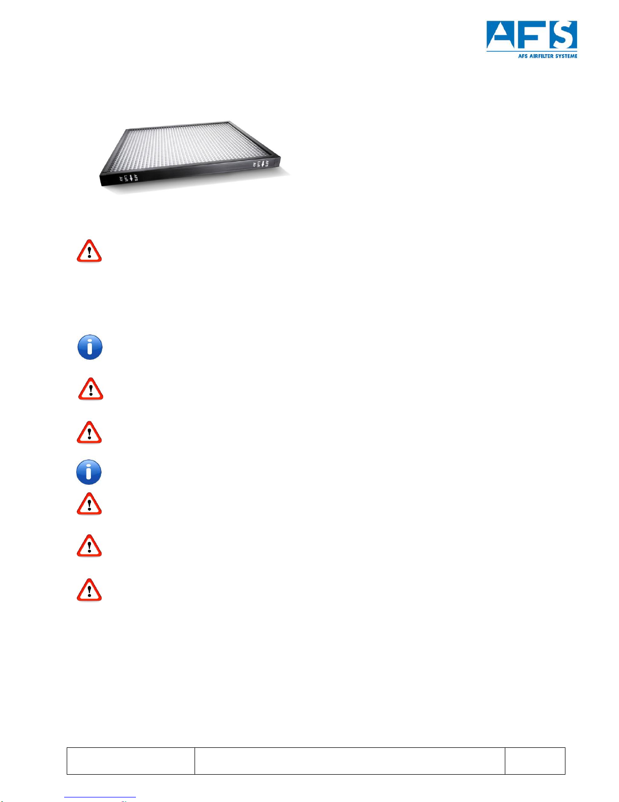
4.2 Design
Figure 1: Exemplary design and component description using an AFS 100 with suction left as an example.
1 Suction on all sides of the device possible
2 Housing
3 Exhaust vent
4 Installation space for motor fan wheel
5 H13 filter or metal mesh follow-up separator
6 Maintenance opening (doors)
7 Hose or pipe connection
O r i g i n a l I n s t r u c t i o n M a n u a l f o r A F S A i r P u r i f i c a t i o n D e v i c e s
f o r R e m o v i n g O i l a n d E m u l s i o n M i s t
Produced By:
Version:
Valid from:
U. Burkhardt
1.05
01/11/2016
Neither transfer or reproduction of these documents nor application or disclosure
of their content are permitted without the explicit approval of AFS.
Violations will require compensation for damages. Page 8 of 26
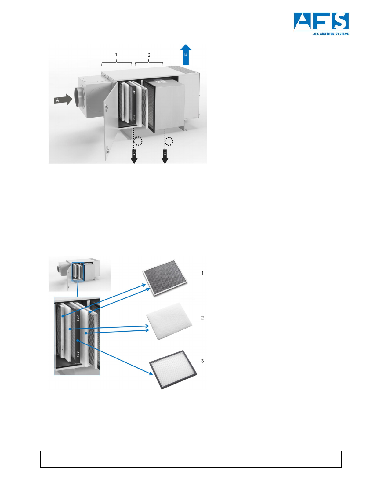
Figure 2: Exemplary description of material flows as well as separator and filter stages using the AFS 1600 as an
example
A polluted machine exhaust air
B purified exhaust air
C separated coolant lubricant/condensate
1 5-stage preliminary separation
2 Follow-up separator
Figure 3: Elements of the preliminary separation in AFS air purification devices
1 Metal mesh preliminary separator
2 Filter fleece (depicted without alternate frames)
3 Longlife separator

O r i g i n a l I n s t r u c t i o n M a n u a l f o r A F S A i r P u r i f i c a t i o n D e v i c e s
f o r R e m o v i n g O i l a n d E m u l s i o n M i s t
Produced By:
Version:
Valid from:
U. Burkhardt
1.05
01/11/2016
Neither transfer or reproduction of these documents nor application or disclosure
of their content are permitted without the explicit approval of AFS.
Violations will require compensation for damages. Page 9 of 26
5 Installation and Startup
5.1 Device Assembly
The device must always be set up horizontally on a rigid and, if possible, vibration isolated base.
The minimum distances between the device and ceilings, walls etc. required to ensure proper operation are:
Top of the device (exhaust air outlet): > 800 mm
Motor side: > 500 mm
Door side: > 800 mm
Bottom of the device (siphon connection): > 500 mm
These minimum distances must be observed to ensure that the device can operate properly.
5.2 Pipe or Hose Connections
Devices for connecting suction pipes or hoses must be arranged as follows:
§Kink-free
§Large bending radius (radius ³diameter)
§About 3° slope toward the air purification device or suction point
§No water pockets or sagging pipes
§If low points are unavoidable, for instance in passages that run below girders, the lowest point is to
be equipped with a condensate drain with a siphon outflow.
The extraction opening on your processing machines should be fitted with a baffle plate to prevent droplets
of coolant lubricant from entering the pipe:
§There should be a ca. 100 mm gap between this opening and the wall
§The cover over the extraction opening should be at least 100 mm on all sides
§The surface of the annular passage should be at least as large as the cross-sectional area of the
suction pipe.
5.3 Siphon Connections
Two ½“outlets (three outlets for AFS 12000 and AFS 16000) are located on the bottom of the device for
draining the coolant lubricant.
A siphon connection must be installed at each opening and filled with coolant lubricant.
The siphon lines must lead to a collection container or a collecting pipe.
The following points must always be observed. Otherwise the device will no longer function
properly.
§Siphon design as a U pipe or loop based on Figure 4.
§The distance between the bottom of the device and the top siphon loop must be:
·At AFS devices 600-1600 at least 200 mm
·At AFS devices 3000-16000 at least 250 mm
§The height of the loop or U pipe must be:
·At AFS devices 600-1600 at least 200 mm
·At AFS devices 3000-16000 at least 250 mm
§The pipe must point downward in the direction of the collection container or collecting pipe.
§No low points or water pockets.
§Each siphon opening must be connected separately.

O r i g i n a l I n s t r u c t i o n M a n u a l f o r A F S A i r P u r i f i c a t i o n D e v i c e s
f o r R e m o v i n g O i l a n d E m u l s i o n M i s t
Produced By:
Version:
Valid from:
U. Burkhardt
1.05
01/11/2016
Neither transfer or reproduction of these documents nor application or disclosure
of their content are permitted without the explicit approval of AFS.
Violations will require compensation for damages. Page 10 of 26
§After the device has been installed or after longer periods of disuse, the siphons must be manually
filled with coolant lubricant. To make sure: When filling the siphon, there must be fluid coming out of
the bottom hose line or pipe!
Figure 4: Siphon installation for AFS air purification devices
Once past the siphons, the drain pipes can be joined into one pipe. See Figure 5 and Figure.6
Figure 5: Properly connected
siphons
Figure 6: Improperly connected siphons

O r i g i n a l I n s t r u c t i o n M a n u a l f o r A F S A i r P u r i f i c a t i o n D e v i c e s
f o r R e m o v i n g O i l a n d E m u l s i o n M i s t
Produced By:
Version:
Valid from:
U. Burkhardt
1.05
01/11/2016
Neither transfer or reproduction of these documents nor application or disclosure
of their content are permitted without the explicit approval of AFS.
Violations will require compensation for damages. Page 11 of 26
5.4 Electrical Connections
Safety Instructions:
Electric motors contain dangerous components that are live and rotate during operation. If operated
incorrectly, used improperly, or inadequately serviced, these components can cause damage to
health and property.
The devices are only to be accessed for work if the system has been disconnected from the power
supply. The devices must also be protected from being accidentally reconnected.
The devices' electrical components, such as electric motors, servomotors,
control and monitoring systems, must be connected as specified in the manufacturer’s instructions
and the regulations of the relevant electricity board.
The German Electrotechnology Federation's (VDE) regulations must be adhered to. Work on
electrical components must be carried out only by qualified electricians.
The drive motors for the ventilator wheels are always fitted with thermostat relays or PTC thermistors
for motor protectors and must be connected accordingly.
5.4.1 Electrical Connection of AFS Air Purification Device
The accompanying instruction manual for the engine or engine fan wheel must be observed.
The German Electrotechnology Federation's (VDE) regulations must be adhered to. Work on
electrical components must be carried out only by qualified electricians.
Once the ventilator motor has been connected, it is vital to make sure that the radial wheel rotates
in the direction indicated by the direction arrow on the front of the device before starting up the
air purification device.
Figure 7: Backward cranked radial wheel with direction arrow
If the rotor rotates in the wrong direction, the motor's direction of rotation must be reversed by
changing the electric poles (reversing the phases).

O r i g i n a l I n s t r u c t i o n M a n u a l f o r A F S A i r P u r i f i c a t i o n D e v i c e s
f o r R e m o v i n g O i l a n d E m u l s i o n M i s t
Produced By:
Version:
Valid from:
U. Burkhardt
1.05
01/11/2016
Neither transfer or reproduction of these documents nor application or disclosure
of their content are permitted without the explicit approval of AFS.
Violations will require compensation for damages. Page 12 of 26
5.4.2 Motor protection
Various motor concepts are built in depending on the device type.
Please inform yourself regarding the built-in motor and its protection devices using the supplied
motor instruction manual or with AFS directly.
The protection devices and installation guidelines described in the motor instruction manual must
be heeded. Make sure that the motor does not restart by itself after a possible fault.
5.4.3 Electrical Connection of AFS Air Purification Devices with Frequency Converters (Optional)
The instruction manual for the frequency converter that is provided and the installation instructions contained
within them must be observed for air purification devices with frequency converters for regulating the flow
rate by controlling the rotation speed of the engine fan wheel.
When AFS air purification devices with frequency converters are operating, a lockable repair switch
must be placed inside the feed line before the frequency converter (DON EN 13053-6.3.1).
The AFS device and the frequency converter must not be serviced unless the frequency converter
and the AFS device have been shut off using the repair switch. While work is ongoing, the repair
switch must be secured with an individualized, lockable closure against unauthorized or accidental
restarting.
The repair switch and the frequency converter as well as the frequency converter and the AFS device
are to be connected by a qualified and competent specialist and in accordance with all current
guidelines and VDE regulations.
AFS partly parameterizes and presets the frequency converters. Adjustments that deviatefrom the
standard are documented in the instruction manual for the frequency converter, see Figure 8.
The currents in the frequency converter are not shut off when the frequency converter's motor is
turned off.
If the frequency converter's operating mode is set to "Motor ON" and the frequency converter is cut
off from the grid, the motor will start immediately once the frequency converter is back on the grid.
Figure 8: Example of basic setting on the frequency converter as altered by AFS

O r i g i n a l I n s t r u c t i o n M a n u a l f o r A F S A i r P u r i f i c a t i o n D e v i c e s
f o r R e m o v i n g O i l a n d E m u l s i o n M i s t
Produced By:
Version:
Valid from:
U. Burkhardt
1.05
01/11/2016
Neither transfer or reproduction of these documents nor application or disclosure
of their content are permitted without the explicit approval of AFS.
Violations will require compensation for damages. Page 13 of 26
5.5 Protective Conductor System
AFS devices must be grounded at the ground plate or ground bolt indicated in accordance with EN60204-1.
Before the AFS device is turned on, the protective conductor system of the entire system must be inspected
and safe operation ensured.
A ground bolt is mounted ex factory. Depending on the device type, multiple locations have been
provided for ground bolts at the base of the device or the carrier.
If necessary, the ground bolts can be mounted elsewhere. The ground bolt is to be connected to the
metal housing structure by a professional.
5.6 Startup Operations
Before the device is turned on, all electrical wires, pipes, ducts, and the AFS device must be examined for
proper installation and mechanical damage and leaks.
Before the device is turned on, all electrical wires, pipes, ducts, and the AFS device must be examined for
proper installation and for mechanical damage and leaks.
The following must be ensured:
§All filter elements must be arranged properly; see Figure 10
§All filter elements must be as delivered
§The motor must be turning in the correct direction
§The AFS device must be securely placed and bolted down at its location
§There must be no debris (shavings, screws, installation materials, etc.) inside the device, the
pipes, or the ducts.
The suction output for AFS devices with frequency converters can be adjusted and readjusted
manually.
The operating principles of all AFS air purification devices are the same; they differ only in scale,
ventilation system performance, and number of filters used regardless of device type.
O r i g i n a l I n s t r u c t i o n M a n u a l f o r A F S A i r P u r i f i c a t i o n D e v i c e s
f o r R e m o v i n g O i l a n d E m u l s i o n M i s t
Produced By:
Version:
Valid from:
U. Burkhardt
1.05
01/11/2016
Neither transfer or reproduction of these documents nor application or disclosure
of their content are permitted without the explicit approval of AFS.
Violations will require compensation for damages. Page 14 of 26
6 Operation
AFS devices can remain in continuous operation.
Operating modes are to be separately described and observed by the operator depending on the on-site
electrical installation.
Sequence and interval operations which involve turning off the air purification device after every
process step cause damage to the AFS air purification device.
6.1 AFS air purification devices without frequency converters
6.1.1 Turn on
1) Turn on the air purification device based on the model series.
2) Pay attention to unnatural noises or vibrations and immediately turn off the air purification device if
they occur in order to avoid damage. Examine the connection and installation and follow the Fehler!
Verweisquelle konnte nicht gefunden werden. section in this instruction manual.
6.1.2 Turn off
Turn off the air purification device based on the model series.
6.2 AFS Air Purification Devices with Frequency Converter (Optional)
An AFS air purification device that has a frequency converter is operated and controlled by means of that
frequency converter. Operation is menu-guided via the arrow keys and the P button. The frequency
converter instruction manual must be observed.
6.2.1 Turning the System On:
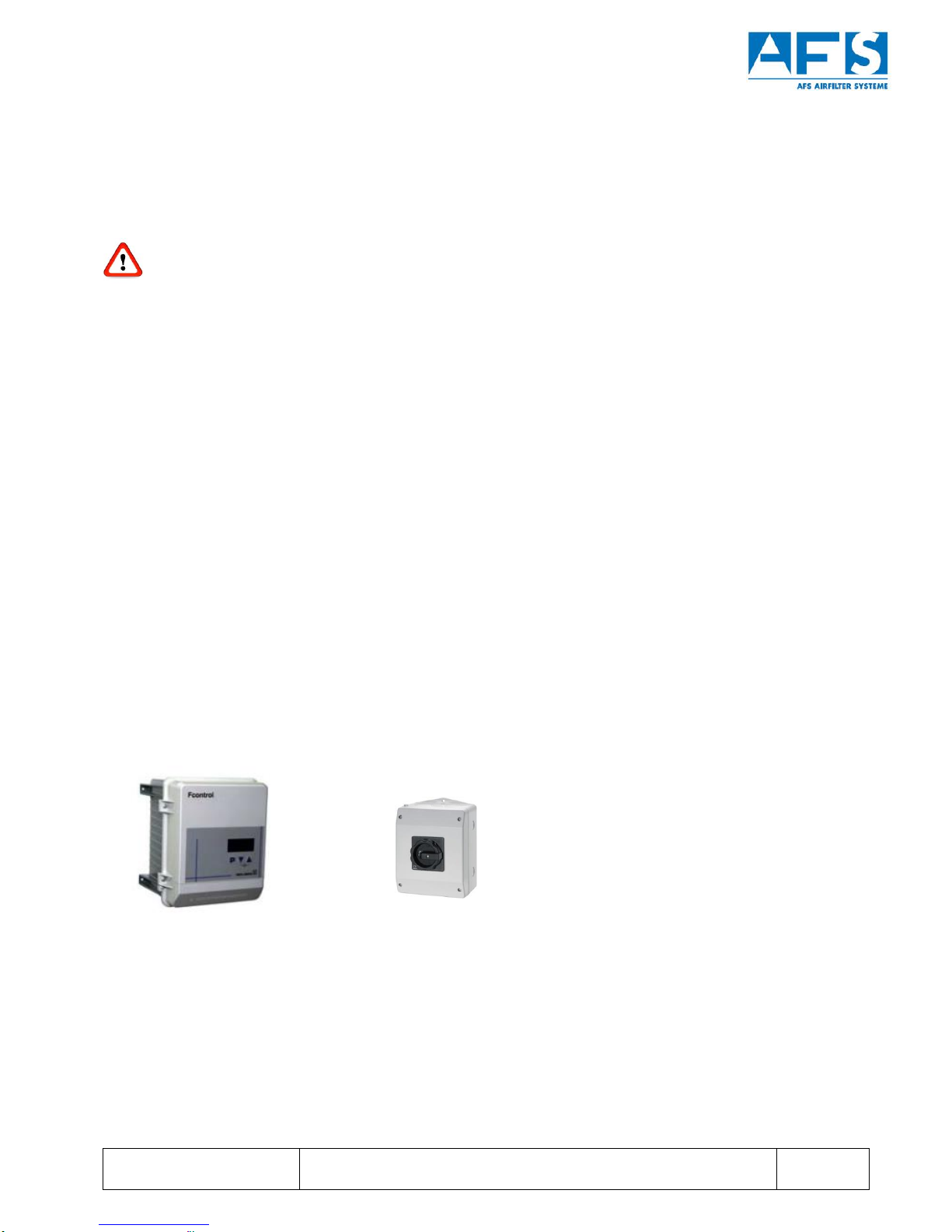
We recommend installing a main switch using it to turn the AFS air purification device on and off. The
operating modes and the suction output are to be adjusted accordingly with the frequency converter.
Figure 9: Example of a frequency converter FControl FXDM...AM and main switch
6.2.2 Switch off the system
Switch on the system according to the model installation on the frequency converter or main switch.

O r i g i n a l I n s t r u c t i o n M a n u a l f o r A F S A i r P u r i f i c a t i o n D e v i c e s
f o r R e m o v i n g O i l a n d E m u l s i o n M i s t
Produced By:
Version:
Valid from:
U. Burkhardt
1.05
01/11/2016
Neither transfer or reproduction of these documents nor application or disclosure
of their content are permitted without the explicit approval of AFS.
Violations will require compensation for damages. Page 15 of 26
Additional Information:
If the frequency converter is parameterized ex factory, then the corresponding parameters will be
noted in the instruction manual that is delivered with the frequency converter, see Chapter 5.4.
The operating modes and on/off procedures can be found in the frequency converter's instruction
manual.
The currents in the frequency converter are not shut off when the frequency converter's motor is
turned off.
If the frequency converter's operating mode is set to "Motor ON" and the frequency converter is cut
off from the grid, the frequency converter will start again at the last selected setting immediately upon
coming back on the grid. Where applicable, the motor may start.
To ensure safe suction output, the frequency converter is not to be operated below its minimum
frequency of 70% of the maximum frequency.
6.3 Follow-up time
The AFS air purification device should continue to run for approximately 10-15 minutes once the process has
ended.
6.4 Motor protection: Acknowledge faults
Various motor concepts are built in depending on the device type.
Please inform yourself regarding the built-in motor and its protection devices using the supplied motor
instruction manual or with AFS directly.
The motor protection is already integrated in EC motors from the manufacturer ebm-papst. In case of fault,
the motor automatically turns off. Before the motor can start again, the fault must be acknowledged and the
motor reset by momentarily disconnecting the power supply.
O r i g i n a l I n s t r u c t i o n M a n u a l f o r A F S A i r P u r i f i c a t i o n D e v i c e s
f o r R e m o v i n g O i l a n d E m u l s i o n M i s t
Produced By:
Version:
Valid from:
U. Burkhardt
1.05
01/11/2016
Neither transfer or reproduction of these documents nor application or disclosure
of their content are permitted without the explicit approval of AFS.
Violations will require compensation for damages. Page 16 of 26
7 Maintenance
Failure to maintain the device as specified in the AFS operating instructions will void the warranty or
guarantee!
7.1 Maintenance Work and Cycles for Oil and Emulsion Mist Separation
All maintenance work on a device must be performed exclusively after the device has been turned off
and by trained personnel familiar with the device.
If multiple AFS air purification devices are operating in conjunction with one another, ALL the devices
must be disabled for maintenance to be performed. Low pressure will persist throughout the entire
extraction pipe system for as long as networked devices are turned on. Where applicable, device
doors must not be opened. There is an increased risk of injury.
Maintenance cycles are to be set in accordance with the type of process and degree of contamination
in the air that is to be cleaned. The degree of pollution in the device as well as the separator elements
must be examined and then cleaned or replaced as needed.
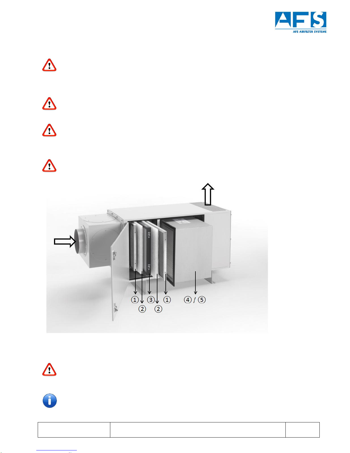
Figure 10: Filter arrangement within AFS air purification devices
Never change the order, number or installation position of the separation and filter elements as this
will render the device inoperable.
The device must only be operated with AFS-approved separation/filter elements.
The separation and filter elements may be laterally removed from the device for cleaning or
replacement.
O r i g i n a l I n s t r u c t i o n M a n u a l f o r A F S A i r P u r i f i c a t i o n D e v i c e s
f o r R e m o v i n g O i l a n d E m u l s i o n M i s t
Produced By:
Version:
Valid from:
U. Burkhardt
1.05
01/11/2016
Neither transfer or reproduction of these documents nor application or disclosure
of their content are permitted without the explicit approval of AFS.
Violations will require compensation for damages. Page 17 of 26
7.1.1 Metal mesh preliminary separator (pos.
•
)
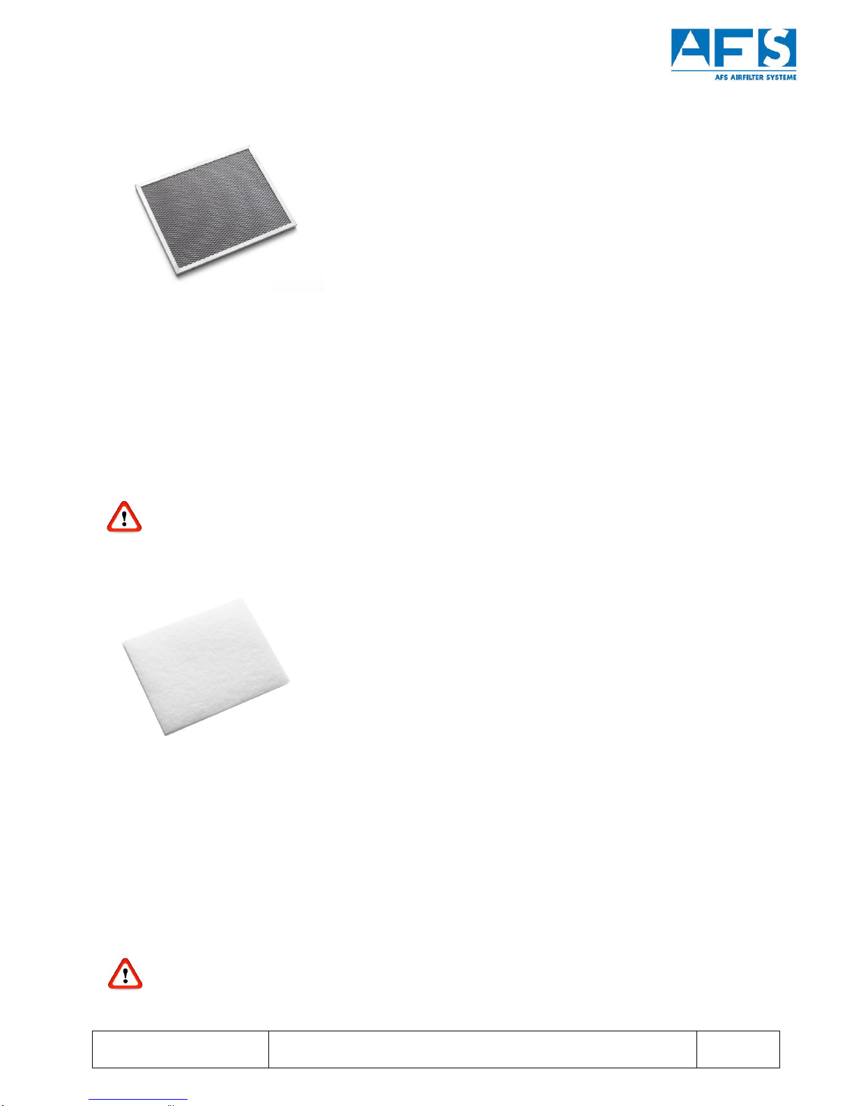
Figure 11: Metal mesh preliminary separator
The preliminary separator is made of a corrosion-resistant metal mesh, is non-wearing, and can be
cleaned/rinsed:
Cleaning interval: Clean when obviously clogged and dirty, i.e. if full of shavings, hardened oil, abraded
material, grease residues.
And at least every 4 weeks.
Directions: Use hot water and a grease-removing cleaning agent with a high-pressure cleaner or
in a component washing system.
Parts will have oil and coolant lubricant residue. Wastewater must be disposed of properly and in an
ecologically responsible manner.
7.1.2 Preliminary filter fleece (pos.
‚
)
Figure 12: Fleece preliminary filter. Depicted without alternate frames
The preliminary filter comprises filter grade G3 filter fleeces, which must be replaced when they become
clogged and dirty.
Replacement interval: Clean when obviously clogged and dirty, i.e. if full of shavings, hardened oil, abraded
material, grease residues.
And at least every 4 weeks.
The preliminary filter fleeces can be replaced with conventional filter grade G 3 filter fleeces with a fleece
thickness of 20 mm.
Parts will have oil and coolant lubricant residue. Proper and ecologically responsible disposal is
absolutely necessary.
O r i g i n a l I n s t r u c t i o n M a n u a l f o r A F S A i r P u r i f i c a t i o n D e v i c e s
f o r R e m o v i n g O i l a n d E m u l s i o n M i s t
Produced By:
Version:
Valid from:
U. Burkhardt
1.05
01/11/2016
Neither transfer or reproduction of these documents nor application or disclosure
of their content are permitted without the explicit approval of AFS.
Violations will require compensation for damages. Page 18 of 26
7.1.3 Longlife separator (pos.
ƒ
)
Figure 13: Longlife separator: Arrow must point in the direction of flow
The Longlife separator distinguishes itself through its high-performance self-cleaning action and must
therefore only be cleaned when visibly and seriously clogged or dirty.
Cleaning: self-cleaning.
If, despite its self-cleaning action, the Longlife separator should nonetheless become extremely dirty
or clogged, i.e. full of oil and emulsion residues, hardened oil, the entire separator can be cleaned
using warm water and a grease-removing cleaning agent.
The Longlife separator must not be opened or disassembled.
It is vital that the separator be installed in accordance with the air flow direction arrows on the
separator’s frame. Otherwise the device will no longer function properly.
If necessary, the writing on the Longlife separator can be arranged upside down relative to the
airflow direction and the installation position.
Damaged Longlife separators must be replaced immediately.
Improperly installed or damaged Longlife separators will cause diminished or unsatisfactory
separation performance. Under those conditions, the device will no longer function properly.
Parts will have oil and coolant lubricant residue. Wastewater must be disposed of properly and in an
ecologically responsible manner.

O r i g i n a l I n s t r u c t i o n M a n u a l f o r A F S A i r P u r i f i c a t i o n D e v i c e s
f o r R e m o v i n g O i l a n d E m u l s i o n M i s t
Produced By:
Version:
Valid from:
U. Burkhardt
1.05
01/11/2016
Neither transfer or reproduction of these documents nor application or disclosure
of their content are permitted without the explicit approval of AFS.
Violations will require compensation for damages. Page 19 of 26
7.1.4 Post filter H13 (Pos.
„
)
Figure 14: H13 post filter
The following are installed as subsequent separators or post filters:
- HEPA filter H13 (Pos.
„
)
- Metal mesh follow-up separator (pos.
…
)
The separation performance of the H13 follow-up separator is higher than that of the metal mesh
follow-up separator (see Chapter 7.1.5). The metal mesh follow-up separator is not recommended
for processing installations which produce smoke and vapor.
The H13 post filter will become clogged in the course of its operation, diminishing the AFS air purification
device's suction output.
If the H13 post filter is clogged or if the air current is significantly reduced due to a saturated filter, then the
H13 post filter must be replaced. To do so, undo the M6 screws on the terminal strips so that the post filter
can be pulled out.
The H13 post filter cannot be cleaned.
Replacement interval: Replace when there is a noticeable reduction in the device’s extraction performance
due to oil and emulsion residue deposits, or hardened oil.
To replace, undo the M6 screws on the terminal strips so as to allow the suspended particle filter to
be pulled out. When fitting a new post filter, the filter’s rubber sealing strips must be on the suction
side (in the terminal area).
The filter bags must be vertical.
If the H13 is not promptly replaced, it may tear. There will therefore be no filtration effect and the
AFS air purification device will be inoperative. The AFS air purification device must be turned off
immediately and a new H13 post filter must be installed.
Parts will have oil and coolant lubricant residue. Proper and ecologically responsible disposal is
absolutely necessary.
This manual suits for next models
8
Table of contents


