Ag-Tester HT101S User manual

1
HT101S Reference Manual

2
HT101S Reference Manual
OVERVIEW
The HT101S from Ag-Tester is our handheld designed to interface with
various sensors found on agricultural machinery and be a complete system
diagnostic tool.
The types of sensors that can be interfaced with include:
Liquid Flow Sensors, Pressure Sensors, Motion Sensors, Shaft Speed
Sensors, Position Sensors and others.
The top section of the HT101S is the meter. The user can make
measurements including Volts, Frequency and Resistance,
The lower part of the HT101S is the diagnostic and sensor simulator center.
When used with the “In-Line” Tester TEE Harness the HT101S will monitor the Voltages supplied to the sensor, from the
display, and additionally allow the signals generated by the sensor to be checked for presence and accuracy. When
dialed to Digital or Analog Simulate, the HT101S sends simulated signals to the display allowing all the connecting cables
to be checked while verifying the Controlling Display correctly reads the signals being sent.
When used with the “Stand-Alone” Tester TEE Harness any sensor can be fully tested on the bench.
The back panel provides connections for inputs and charging along with the magnetic RAM Mount.
RAM MOUNT/ MAGNET
INPUT CONNECTOR CHARGER INPUT
Connect the Tester TEE
Harness Here

3
METER FUNCTIONS
The “Meter Function” switch selects the type of
measurement being made. Select from the following:
VOLTS 0 to 50 Volts DC with automatic polarity sensing
FREQ Frequency 0 to 1000 HZ
CONT “Continuity” or “Ohms” 0 to 2000
The “Connected Point” switch selects the testing method.
There are 4 options. TEST, PATCH, COAX, or BATT CHECK
When dialed to TEST the
standard meter test leads are installed in
the RED outlined lead jacks. The meter can
then be used as you would a standard test
meter.
Dial to PATCH to use the Patch Cables
connecting at the Green outlined lead
jacks. This allows an easy connection to
the wires connecting the Display console
to the sensors.
Setting the CONNECTED POINT to COAX allows for an
easy connection to a TNC type coax connector. Most GPS
receivers send 5 volts to the antenna to operate an
internal amplifier. Disconnect the cable from the gps
antenna and re-install at COAX on the HT101S. When
VOLTS is selected you should see 5 to 12 volts on the
meter indicating a good connection from the antenna
connection to the gps receiver.
When dialed to BATT CHECK and VOLTS the meter indicates the
current internal battery voltage. Fully charged it may read as high as
13.5 VDC. The tester will function properly until below 12 volts. No
wire connection is required. Battery can be checked while
performing other tests.
The “Pulse Catcher” LEDs blink when pulses are present on the wire
being tested. This function is active when “Frequency” is selected.

4
DIAGNOSTIC FUNCTIONALITY and SENSOR TESTING FUNCTIONS
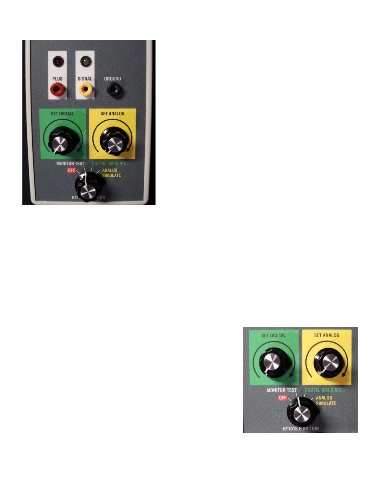
The HT101S Function Switch is located in the lower, center position of
the Tester. When dialed to any position except “OFF” the meter
functions are all available.
Set to MONITOR to use the Tester as a standard meter or to make tests
of the complete connection of the Display to the Sensor being tested.
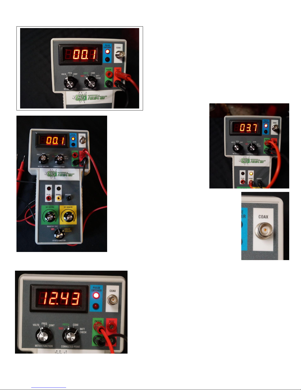
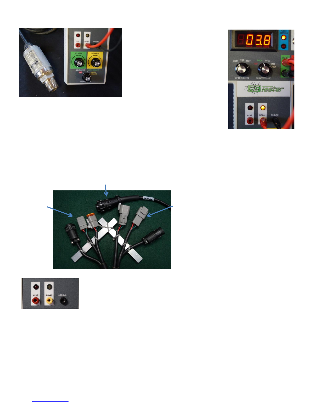
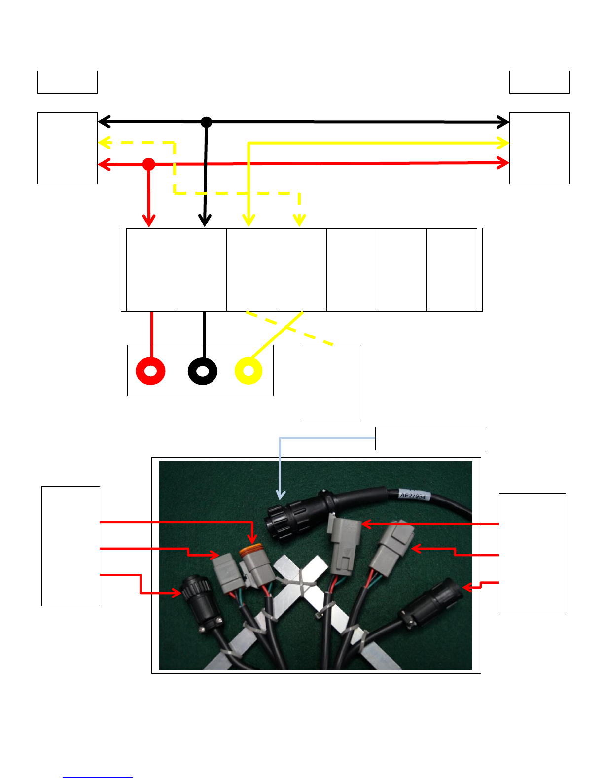
When connected using the “In-Line” Tester TEE Harness, there are 3
possible connections made available for tests. A 3 wire sensor will have
a ground, a positive supply voltage and a signal line. The HT101S makes
these connections available for testing with Test Jacks and any voltages
present will be displayed by the associated LEDs.
Test Jacks and LEDs are colorized to indicate:
RED = Supply Voltage from Display
Yellow = Signal
Two wire sensors won’t have a wire for power. These might include magnetic sensors and switches.
When dialed to “DIGITAL SIMULATE” two test functions are made available depending on the type of connecting harness
being used.
When using the In-Line harness, DIGITAL SIMULATE allows the HT101S to send a continual Test Signal back to the
Display. These are digital pulses where the frequency of the generated test signal is controlled by the “SET DIGITAL”
control. When fully counterclockwise the signal is at about 30 Hz or 30 pulses per second. Turning the control clockwise
will increase the frequency to 350 Hz or so. This is a sure way to locate cable trouble from the sensor to the display while
at the same time verifying the display is programmed to receive these digital signals.
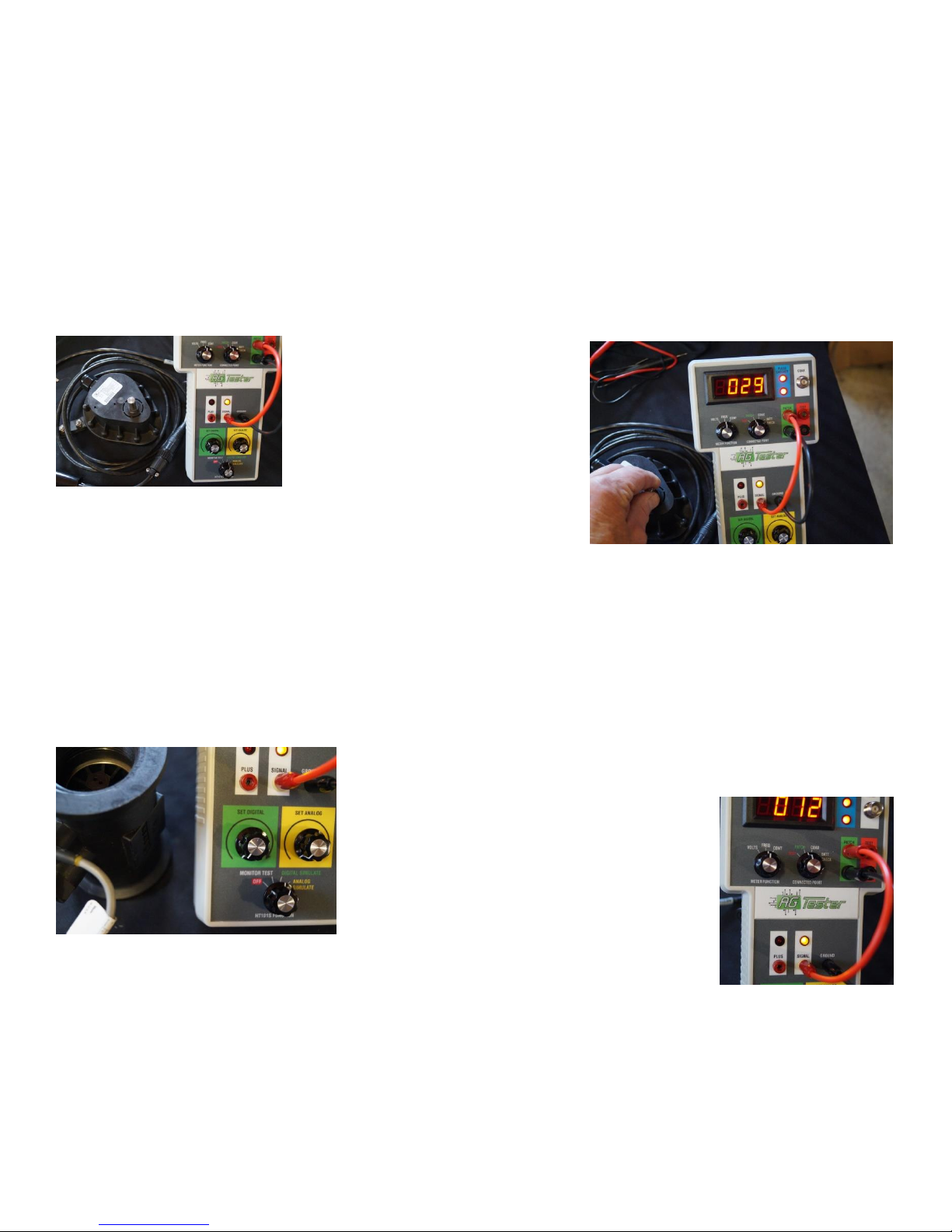
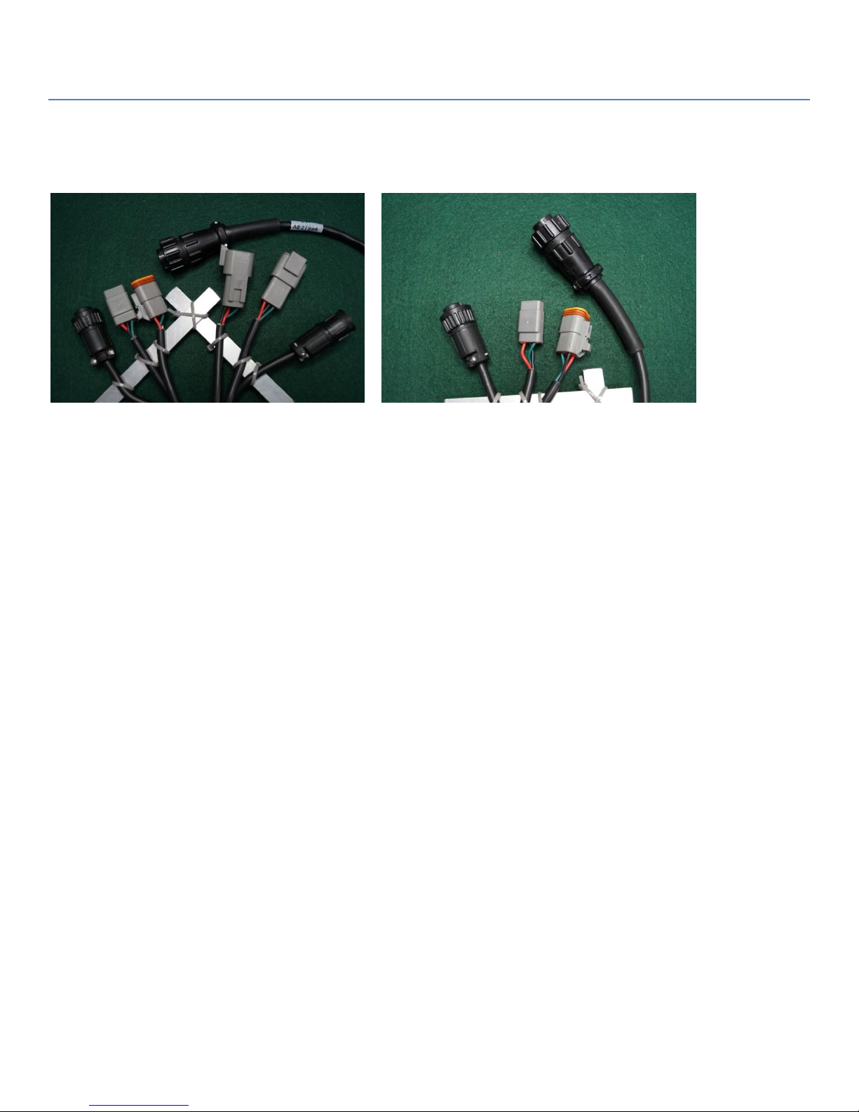
When the Stand-Alone harness is used, DIGITAL SIMULATE is used to check the sensor, independent from the display.
The HT101S provides the Supply Voltage and the Signal Generated is available for tests at the YELLOW test jack. You’ll
see the Yellow LED blink as the pulses are generated and the Frequency can
be read by connecting the Meter to the Yellow and Black test jacks.
SET ANALOG allows the same type of tests to be performed but are used
with Analog Sensors.
When the In-Line harness is connected you can monitor the Supply Voltage
and the Generated Signal from the display to the sensor.
The Stand-Alone Harness allows for testing of the sensor independent from
the Display. The HT101S provides the Supply Voltage and Ground and the
generated signal is made available for test at the YELLOW test jack.

5
TYPES OF SENSORS TO BE TESTED
The HT101S is designed to be compatible with any sensor on any machine. In some cases special cabling is needed.
These sensors require in some cases, very specific operating voltages. Sensors generally fall into two groups; DIGITAL
and ANALOG.
DIGITAL sensors generate PULSES which vary in FREQUENCY as changes occur.
Shaft Speed sensors are used in many applications from Dry Product Applicators
to Planters. They will generate a certain number of “pulses per revolution”. The
RAVEN sensor to the right generated 180 pulses per revolution. Others might
generate 60 or 360 pulses in a single revolution. This is the reference point for
the display. Cutting the pulses in half tells the console the shaft is running at half
speed. Doubling the pulses indicates double the speed. “Pulses per revolution” is
the calibration reference the display requires.
Flow Meters generate pulses reflecting the amount
of flow currently running through the meter. A
calibration Tag is generally attached and indicates
the “Pulses Per Gallon” generated by the sensor. This RAVEN Flowmeter has a
tag showing 730 which in the case of RAVEN indicate 73 pulses generated per gallon of liquid flow. The generated pulses
are linear in their output meaning, doubling the pulses means double the gallons.
ANALOG sensors have signals that vary in VOLTAGE as changes occur.
The graph to the left shows how a 100 pound pressure
sensor varies in voltage generated as the pressure
changes. Zero pounds of pressure is indicated with a
voltage generated of zero. At 100 pounds of pressure the
signal voltage is at 100. The sensor responds in a linear
fashion. 50 pounds is then indicated by a 2.5 volt signal.
A zero to 3000 pound pressure found in hydraulic systems
will also respond in a linear way with zero volts indicating zero pressure and a 5 volt
signal is generated at 3000 pounds.
Another analog sensor might be a POSITION SENSOR used to indicate the steering position on a GPS Auto-Steer System.
Hitch position sensors are also this type. Movement is indicated by a linear change in voltage.

6
Using the HT101S Stand-Alone Testing
Stand-Alone testing is used as a method of testing and evaluating or “bench testing” a sensor, independent of the
display.
Use the Tester TEE Harness and adapters if required to match the sensor being tested. Sensors are very sensitive to
correct voltages being applied. Some are 12 volt supply where others are specific at 8 volts or 5 volts. There are sensors
that work with a great variety of supplied voltages.
We’re using the Tester Tee Cable, TT- AE27993 Stand Alone in the following tests.
Shaft Speed Sensors
Set the Function Switch to “Digital
Simulate. Set the Meter Function to
“FREQ”, Frequency. Set the Connected
Point to “Patch “ and install the Patch
Cables from the Meter to the Yellow
and Black Test Jacks. As you slowly turn
the shaft of the sensor you’ll see the Yellow LED Blink as the pulses are
generated. The faster you spin the shaft, the faster the light blinks. You
can read the Frequency of the generated pulses on the meter.
These are best tested using a variable speed drill. Holding the speed constant should provide a steady frequency output.
These sensors may become unstable in frequency with the shaft speed constant. If the sensor is on a machine, just
watch for a steady frequency indication with a constant shaft speed.
Flow Sensors
Flow Meters can be bench using the HT101S set up as done for the Shaft Speed Sensors.
Set the Function Switch to Digital Simulate. Set the Meter Function to
Frequency and the Connected Point to Patch. Install the Patch Cables from the
meter to the Yellow and Black Test Jacks.
Blow through the flowmeter and the turbine will
spin. As the turbine spins pulses are generated.
You’ll see the Yellow LED Blink and the Frequency
can be read on the meter. The Pulse Catcher will
blink indicating pulses are present.

7
Pressure Sensors
When testing Pressure Sensors set the
Function Switch to Analog Simulate. Set
the Meter Function to Volts and the
Connected Point to Patch. Install the test
leads from the meter to the Yellow and
Black test jacks.
Typically ZERO Pressure will result in a
signal voltage of 0.5 Volts As the pressure
increases the voltage increase smoothly until maximum pressure indicated by a signal of
5.0 volts. 1/2 Pressure will generate 2.5 volts of signal. You can easily test these sensors
while installed on a machine. Zero to 100 pound sensors can be tested on the bench using
air pressure regulated to provide the test pressures. Hydraulic pressure sensors need
typically 3,000 pounds of pressure which can be a challenge providing on the bench.
Using the HT101S In-Line Testing
Use Tester TEE In-Line Harness TT-AE27994
To Tester
To Sensors To Display
Install the harness between the sensor and the display. The Red and Yellow LEDs indicate
voltages coming from the display and sensor. When installed the RED power LED will light. If
not either the cable is bad going back to the display or the display is not turned on. The
Yellow LED may be lit or not depending on the status of the sensor. The signals from digital
sensors like Flow Meter and Shaft Sensors vary from Zero to 5 volts generally. The light will blink indicating pulses.
Use the Patch Cables checking the Display Power at the RED and BLACK Test Leads. Check the signal Voltage and
Frequency using the Black and Yellow Test Jacks.

8
Battery Care- HT101V and HT101S Testers
These testers are equipped with a high power, 12 volt 1000 MAH Nickel- Cadmium “NI-
Cad” battery. The testers will run about 10 hours constant without a re-charge. Re-
Charge takes about 4 hours.
The battery level can easily be checked using the voltmeter built into the tester.
Turn the tester ON, set to VOLTS, and Connected Point
to BATT CHECK. The current voltage will be
displayed.
After a full charge, it may read in excess is 13 volts, then will stabilize at about 12.2 to
12.8 volts.
Ni-CAD batteries develop a memory over time. If they are recharged after each short
usage, they will develop that memory and at some point only deliver that capacity. MAXIMUM battery life with the
strongest usage cycle is achieved by charging the battery when the voltage drops below 12.0 volts. Check the voltage as
your putting away the tester. If the voltage is 12.0 volts or less, recharge.
Use only the SMART CHARGER that came with the tester. The charger will turn
itself off when the battery is charged so there is no chance of
overcharging.
The charge indicator light turns RED when charging and when fully charged the
light turns green.
Batteries are replaced at Ag-Tester. Go to agtester.com for details.

9
Tester- Tee Harnessing
To understand the flow of circuits and over-all Ag-Tester product design, one needs to start with an understanding of
the interface harnessing, “Tester-Tee Harnesses”. Two harnesses are used for full Tester functionality.
TT- AE27994 In-Line Harness TT- AE27993 Stand-Alone Harness
1- In-Line Harnessing. This is used for full system diagnostic operations where the full connection from the
display to the sensor or valve is intact. Here, the system is left intact with the Ag-Tester Tool inserted in the line
feeding the Valve or Sensor in question from the balance of the system.
a. When in the “monitor mode” “Tip Jacks” are available representing each possible connection between
the component and the rest of the system. This provides a connection point for either, the Ag-Tester
Tool or another meter, oscilloscope or some other tool so tests can be performed to determine the
cause of the problem.
b. When in the other provided “modes of operation” the circuit control lines are disconnected between
the component and system balance to allow for diagnostic functions to be performed.
i. The “HT101S” allow the sensor to be independently tested while at the same time sending
feedback to the system balance to allow for diagnostics.
2- Stand-Alone Harnessing. Stand-alone harnessing allows for components to be “bench tested”. Using the
stand-alone harness allows that the Ag-Tester Tool provides the operational power and signals to the devise
being tested to fully test the component.
a. Monitor mode is not used unless using the Tester as a “multi-meter” for basic tests.
b. When in other modes of operation, the type of test being performed is selected. The Tip Jacks do not
represent the “Power Supplied” “Red LED” using this function.
i. The HT101S allows for either digital or analog sensors to be tested with the HT101S providing
operational power and signal paths for analysis. The test jacks and Led indicators are available
for tests on signal lines.

10
Sensor
Display
To Sensor
1
2
3
To Display
A
B
C
In-Line Harness for Sensors-HT101S
Ag-Tester Tool- HT101S
Tip Jacks and LEDs
1
+
Power
from
Display
2
-
Power
from
Display
3
Signal
to
Display
4
Signal
from
Sensor
5
Ground
from
Tester
6
+5
Volts
from
Tester
7
+12
Volts
from
Tester
Ground (-)
Signal
Power (+)
Ground (-)
Signal
Power (+)
Digital
and
Analog
Simulator
To Tester- 7 Pin AMP

11
To Sensor
12 Volt 1
12 Volt 2
5 Volt 3
Stand- Alone Harness for Sensors- HT101S
Tester Wiring
1
+
Power
from
Display
2
-
Power
from
Display
3
Signal
to
Display
4
Signal
from
Sensor
5
Ground
from
Tester
6
+5
Volts
from
Tester
7
+12
Volts
from
Tester
Tip Jacks and LEDs
Sensor
Ground (-)
Signal
Power (+)
Sensor Connector
determines power
+(5) or +(12)
“Pull-up”Resistor to
+5V with MODE at
DIGITAL
To Tester- 7 Pin AMP

12
Please look to agtester.com for help in solving your troubleshooting needs. Feel free to contact us at the web site
or at:
Ag-Tester
PO Box 164
Spencerville, OH. 45887
Office Phone: 419-667-4008
WARRANTY
All Ag-Tester products are fully warrantied to be free from any problems for a period of ONE YEAR from the date
purchased as an end user.
Any defects whether caused by an electronic failure or some assembly issue will be repaired at no charge.
You are responsible for the shipping costs to Ag-Tester. We will return, repaired, at our expense.
Thank you for your purchase.
John C. Dignan- Founder and Senior Engineer
Ag-Tester
Table of contents
Other Ag-Tester Test Equipment manuals