Ag-Tester CT1000 User manual

1
CT1000
Reference Manual
100% of the product design, manufacturing and support is done in the USA, mostly at our base of
operations in rural, Venedocia, Ohio. Please contact us at agtester.com for any support
needs. Thanks!! John C. Dignan Founder and Senior Engineer Ag-Tester

2
IntroductionCT1000 Cable Testing System
100 Years of Evolution in Cable Troubleshooting Tools
Cables can be easy to troubleshoot, if you observe the correct process, have a meter of some sort and two people.
The diagnostic process can be time consuming but will diagnose any potential trouble. The process has stayed the same
from the very early days of telephone systems back in the early 1900s, here in the US. Unfortunately, the tools haven’t
changed much either. They look different and some are more complicated, but they all will check a cable properly.
The photo to the left
really makes the point
about test tools for field
technicians. Nothing
changed until the CT1000.
In the early 1900s a
simply “Ringer” did the
trick. Turn the crank, and
if the bell sounded there
was a connection.
Analog meters were
developed with digital
meters coming along in
the 1970s.
The CT1000 is the first Cable Testing System ever developed that allows a single user to fully test and isolate trouble
with cables associated with the electronics involved today on field vehicles and implements without removing the cable
harness.
The Patent Pending design of the CT1000 is unique in that:
1- The cable can stay in place on the machine.
2- All the wires are tested with a single Tester hook-up, without any additional effort by the user
3- Only one person is needed to perform the tests, unless severe intermittent conditions exist. Then someone
else is needs to watch the LED alarm indicators on the CT1000.

3
Testing Cables Using an Ohm Meter
Testing cables when the technician only has access to one end of the cable for a meter connection can be done with a
traditional Ohm Meter or continuity tester. Completely testing a harness can be very time consuming and it’s very easy
to miss intermittent connections.
The process used for testing is the same today as it was many years ago. Two people are generally required. One Tech is
at the cable end with a meter and the other Tech moving a jumper wire at the opposite end of the harness.
Basic examples using an Ohm Meter are shown below.
Multi-wire cables can be tested using the same process. Test the wires one at a time for continuity, “zero ohms”. Then
check for shorts between wires. Establish a COMMON connection point for the test. We’re using the BLACK wire #1 as
common.

4
When checking for shorts between wires check the wires one at a time. Use one wire as the COMMON. We’re using the
BLACK wire #1 as common.
To check wire 5 for shorts hook the meter leads to
1 and 5. Then hook connect jumpers from wires 1
to 2, 1 to 3,and 1 to 4. That shorts all wire to
common except the wire 5 being tested. Then
move the meter leads to 1 and 4 while shorting to
common wires 5, 3, and 2 to the common #1 wire.
Repeat the process until all the wires have been
checked.
The process is time consuming, but it works.
Where things really get complicated is where multiple connectors are involved especially when there are multiple wires
connected to a single wire connection. Many times the power wires and others are common to multiple connectors.
This cable has 24 wire connections at the MMR connector. The MMR is then hooked to 10 different connectors going to
different pieces of the system.

5
The wiring table below shows how the connections are made from the MMR connector out to the system components.
Even this complex can be tested with the old
Ringer or any meter but it is very time consuming
and there are lots of places for errors to occur.
When intermittent connections are a problem
the old methods of testing are close to
impossible to use.
The CT1000 is a cable testing system. When testing the cable above the CT1000 would connect at the MMR connection.
TERMINATORS are installed at individual connectors involved in the test.
If the entire cable is being tested, 10 terminators would be installed at the cable ends. If your only concerned about one
function, say the Fertilizer Function, a single terminator would be installed at the FRT connection. All other components
should be unplugged during the test.
The TERMINATORS give the CT1000 a reference connection. From this reference, a SHORT is indicated if the reference is
below the target and an open is displayed if the reference reading is too high.
This allows the CT1000 to very accurately display the status of the cable. One technician can do the troubleshooting job
even when connections are intermittent.
MMR “Main”
Connection
Each Vertical Row shows the
pin number used for that
function. Note FRT uses 8
wires.
Notice Wire 1 at the
MMR is connected to
both the WLR and PL
connections.

6
Panel Layout and Component Details
Charging Jack
Set Number of
Terminators
wires 1,2,3
Sounder
Alarm and
on/off Switch
Input
Connectors
Power On/Off and
Battery Level
Chassis
Ground
Wires
1-12
Control
Wires
13-24
Control
Alarm Status and
Alarm Control
Wires 1-24

7
CT1000 Component Details
Use only the Smart Charger that is provided with the CT1000. The battery
is a 7.5 Amp/Hour sealed lead-acid battery that will provide as much as 20
hours of continual use by the Tester.
When power is applied the Battery Status Lights indicate the currently available power.
Normally the LEDs for 10V through 12V Status Lights are lit. The 13V LED comes on when
charging or for a short time after a full charge.
The charger can be used while the CT1000 is in use.
The CT1000 will continue to operate with just slightly above 10Volts, but it should be
charged when below 12V.
Two Input Connections are provided for cable inputs to the CT1000.
The pins are numbered starting at the upper left as pin one. The pin numbers then go
from left to right and from top to bottom.
J2 has pin 1 and 2 in row one. Pins 3,4,5 and 6 in row two. Pins 7,8,9and 10 in row three
and so-on.
The pin number of J1 and J2 become the WIRE NUMBERS of the CT1000.
J1 will work for up to 24 wire cable testing and J2 handles up to 12 wires.

8
There is more Information in the Cable Testing Section of the manual.
The Wire Control Switches are set up in groups of 12 wires each.
The Top Switches control whether a wire is to be tested or not. Switch UP
for TEST and DOWN for not test.
When testing for shorts between wires, the user can SWITCH to LEFT to
create a short on a particular wire.
There is more information in the Using the Tester Section of the CT1000
Manual.
The Wire Alarm Status Lights are also split into groups of twelve.
OPEN wire conditions are indicated with a YELLOW LED
SHORTED wire conditions are indicated with a RED LED.
When NO FAULTS are detected, no alarm LEDs are lit and the GREEN
ALL OKAY is ON.
If an open or short occurs the yellow or red alarm led lights and the
green all okay light goes out.
When the alarm condition occurs, the RED ALARM LED lights up and the SOUNDER alarms. The alarm LOCKS until the
fault condition clears and the RESET switch is pushed.
The SOUNDER is loud and can become outright annoying when troubleshooting. The sounder
ON/OFF switch allows the user to silence the sounder and still have the LED Alarm indicators.
The GROUND STUD allows for a connection to COMMON
where shorted wires to chassis of implement frame are a
concern. Use a standard vehicle “jumper cable”to make a
connection from the CT1000 to the frame or chassis involved.
The CT1000 will display “shorts to chassis”.

9
Becoming Familiar with the CT1000
We use the following procedure to “Proof” or final test the CT1000 before shipping. Going through at least part of the
procedure will help give you a solid feel for how it is wired and how it works.
Start with the CT1000 turned off. Set all wire control switched to NO TEST. Set
all SHORT switched to NO SHORT or switched to the right.
Turn the sounder on. No input connected.
Turn ON the CT1000
The Blue Battery level lights will light up indicating the currently available
VOLTAGE LEVEL. LEDs indicating 10V, 11V and 12V should be on. Connecting
the CHARGER or a very fresh charge will light the 13 volt light.
The GREEN ALL OKAY lights will light up indicating no problem present.
Set a single wire to TEST as we used #3
The GREEN “ALL OKAY” LED goes out and the ALARM LED lights up indicating
a problem in wires 1 through 12. The SOUNDER turns on, sounding the
audible alarm.
The YELLOW ERROR LED lights up indicating WIRE #3 is open. That’s because
there is no input connected.

10
Turn the wire OFF, in our case WIRE #3.
The YELLOW ERROR LED goes out and the ALL OKAY LED comes back on
indicating NO CURRENT PROBLEM.
The RED ALARM LED stays on until RESET and the sounder continues.
Press the RESET BUTTON to reset the alarm LED and silence the SOUNDER.
Now both GREEN ALL OKAY lights are on, again ready for a test.
Now set a wire control switch from the 13 through 24 wire group to TEST.
In our case we used wire #17
The OPEN ALARM LED, YELLOW, comes on for wire 17. The green all okay LED
goes out and the alarm LED lights for wires 13-24. The sounder comes on
unless switched off.
Plug in the CHARGER and verify the 13V LED comes on indicating a charge
above 13 volts.
The CT1000 can be used in the field with the charger running when needed.

11
Set the Wire back to NO TEST. In our case wire #17
The GREEN ALL OKAY LED for wires 13-24 comes on indicating NO CURRENT
PROBLEM. But the RED ALARM led and the sounder continue until RESET.
Press the RESET BUTTON to silence the alarm.
Turn ON ALL WIRES starting with one through 12 verifying that as a wire is
activated the OPEN, YELLOW LED comes on indicating the correct error and
number sequence.
Continue setting the wires to TEST for the balance of the wires watching
that the correct indicator comes on with the wire control switch.

12
The SOUNDER can be turned OFF for the tests.
ALL WIRES will show YELLOW OPEN condition
Attach a TEST LEAD from the CHASSIS GROUND or COMMON connection
to each wire on the 16 PIN INPUT CONNECTOR.
VERIFY GROUNDING EACH WITH 1 THROUGH 12 MATCHES ERROR
INDICATORS 1 THROUGH 12.
The ERROR INDICATOR will show SHORT “RED” for EACH wire tested.
Continue Testing EACH INPUT CONNECTION verifying the “pin number
versus Alarm ID.
Verify ALL connections on the 37 pin input connector.
Wires 1 through 24 should be verified as correct.

13
After confirming ALL INPUT pins as correct, switch the WIRE SHORT
SWITCHES to SHORT and verify all match switch with wire indicator.
CHECK ALL 24 WIRES
Set all switches back to NO TEST and RESET ALARMS
Turn the SET TERMINATOR SWITCHES from position one through five.
The alarm will sound when dialed off position 1.
Verify the STOPS are set to 5 positions. Switches will stop at position 5.
Check ALL SET TERMINATOR SWITCHES .

14
When completed the CT1000 is
ready for the field.
Turn the power switch “OFF”
when completed.

15
Cables and Terminators for the CT1000
Connecting the CT1000 to a cable requires an adapter cable to go from the cable harness being tested and the CT1000.
Terminators are also required. You can build them yourself or purchase from Ag-Tester or a company offering the
CT1000 cable testing system.
The first step in creating a cable is to create a
chart that allows you to see the CT1000 pin-
outs along-side the harness connection.
Creation of the chart requires great care
insuring the connections are correct, common
wires are determined and the number of
terminators on a single wire determined.
The CT1000 will use wires 1,2 and 3 where
multiple terminator connections are present.
Common wires are connected to pins 35,36 and
37 of J1 and 15 and 16 on the 16 pin J2.
Once the chart is finalized the adapter cable
and terminators can be built.
The chart to the left was adapted to include the
CT1000 connections. With the CT1000
connections in the row directly left of the
harness connections it’s easy to identify the wires involved when the CT1000 displays errors. The chart below was
adapted to include the CT1000 pin numbers as part of the chart. Using the modified chart, the user can easily identify
the wire in question.
Notice wires 1 and 2 are hooked to MMR
pins 2 and 10.
2-5 indicates the CT1000 wire 1 is hooked to
MMR pin 2 and has 5 terminators attached.
Set the “Number of Terminators” to 5 for
CT1000 wire 1.
Set CT1000 wire 2 to 2 terminators as shown
on the chart.

16
These charts are available from Ag-Tester when purchasing the adapter or from the manufacturers support group.
If you’re building you own adapters make this chart a priority. You’ll find the troubleshooting process goes a lot
smoother.
If you have any questions or comments as you work with the CT1000 contact us at agtester.com.
Warranty
The CT1000 is fully warranted against any failures related to parts, components and labor for a period of one year from
the time of purchase by the end user.
If you do experience a problem please contact us at agtester.com or give us a call at 419-667-4008. Our address for
shipping is:
Ag-Tester
18629 Jones Road
Venedocia, Ohio 45887
If service is required under warranty the user is responsible for shipping the unit to us. We will repair at no charge and
return by UPS ground at our expense.
We expect your total satisfaction.
Please visit agtester.com for accessories for the CT1000 and take a minute to view our other testing products.
The HT101V is a Hand-Held Tester designed to interface with control valves.
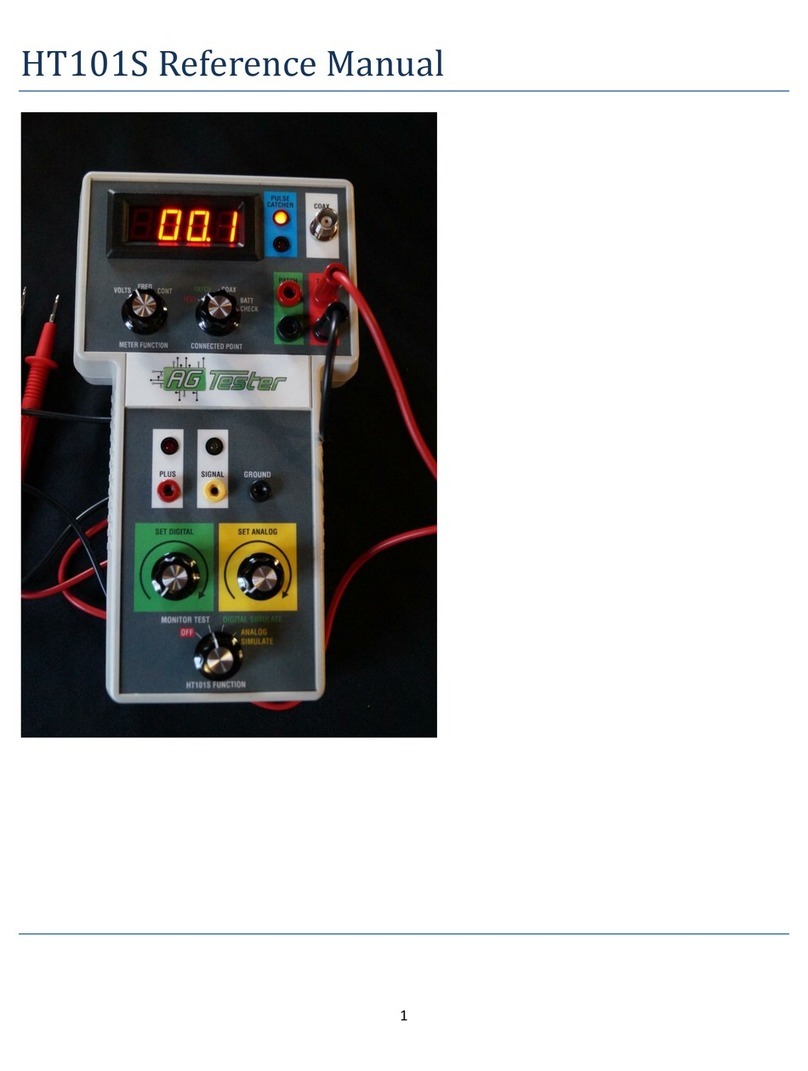
The HT101S is a Hand-Held Tester which interfaces with sensors used on machines.
The PWM1000 is a driver for PWM valves.
Videos available at Ag-Tester.com
Thanks for your purchase!
John Dignan Founder and Senior Engineer Ag-Tester

17

18
Table of contents
Other Ag-Tester Test Equipment manuals