Min DS202 User manual

User Manual
DS202
Version 1.0
Contents
Important Safety Information
P1
Chapter 1 Overview of DS202
P2
Chapter 2 Introduction to
Interface
P6
Chapter 3 Start Guide
P9
Chapter 4 Basic Function
P14
Chapter 6 Battery Disposal
P21
Chapter 5 Product Inspection
P20
Chapter 7 Technical Support
P22
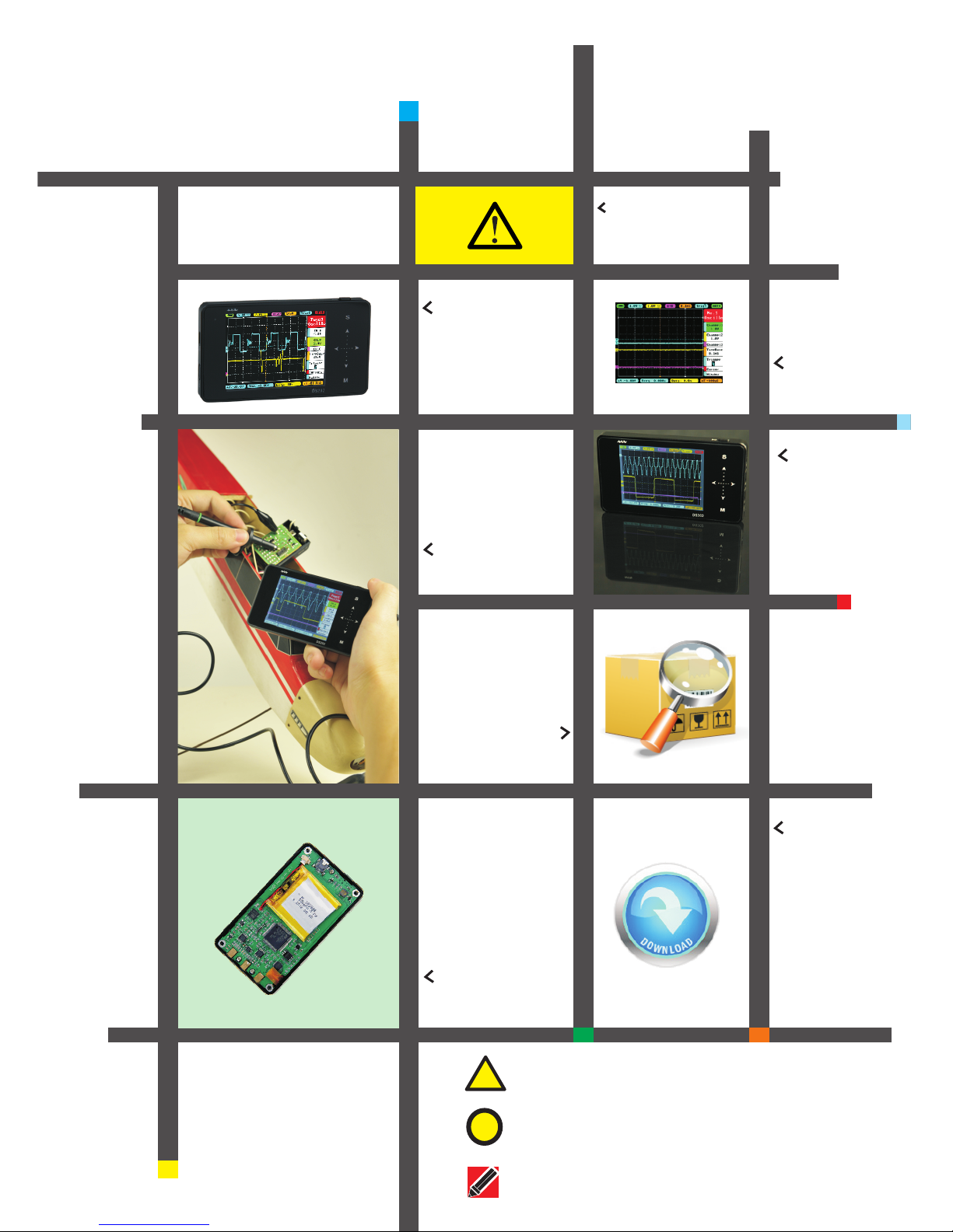
!Warning: Warning statements identify conditions or practices
that could result in injure yourself or others
!Caution: Caution statements identify conditions or practices
that could result in damage to your device or other property
Attention: Attention statements identify annotations, usage
tips or additional information
This user manual is
based onAPP V1.28
1
● Read carefully all the following safety precautions to avoid personal injury
and prevent damage to the device or any products connected to it. Failure
to follow these safety instructions could result in personal injuries or risk of
fire.
● Use proper power cord. Please use power cord specified for this product and
certified for your country/district of use.
● Connect and disconnect properly. Do not connect or disconnect probe or test
leads while they are connected to voltage source. Disconnect the probe
input and the probe reference lead from the circuit under test before
disconnecting the probe from the measurement instrument.
● Observe all the terminal ratings. To avoid fire or shock hazard, please do not
measure signals at DC40V or above. Consult the product manual for further
ratings information before making connections to the device.
● Do not operate in wet/damp conditions.
● Do not operate in a potentially inflammable/explosive atmosphere.
● Please keep the surface of the product clean and dry.
Safety Statement
General Safety Information
Wa
r
n
in
g
Wa
rn
ing
Wa
rn
i
ng
Operating Environment
Temperature
Operating Condition +0°C 到50°c:
Non-operating Condition: -20°c 到+60°c
Humidity
Operating Condition High Temperature:40°C 到 50°C,: 0% 到90%RH
: Low Temperature 0° C 到 40°C,10%到90%RH
Non-operating Condition: High temperature:40°C 到 60°C,5%到95%RH
Low temperature:0° C 到 40°C,5%到95%RH
Requirement
Operating Environment
Performance parameters
Analog bandwidth
1MHz
Maximum sampling rate
10MSa/s
Maximum sample memory depth
8K
Analog input impedance
1MΩ
Maximum input voltage
±40V(X1 probe)
Coupling
AC/DC
Vertical Sensitivity
20mv/Div~10V/Div (in 1-2-5 sequence step)
Horizontal time base speed
1uS/Div~2S/Div(in 1-2-5 sequence step)
Over view of DS202
Chapter 1
Specifications
2

Over view of DS202
Chapter 1
Specifications
3
Functional parameters
Autonomous channel reveal A,-B,A+B,A-B,RecA,RecB,RecC operation waveform
Mode Contain Auto,Normal,Single,None,Scan synchronous mode
Trigger mode ascend/descend Edge trigger mode
Setting modes available set adaptive level, vertical range, trigger threshold mode
Waveform Functions Auto measurement frequency/cycle time /duty cycle, voltage peak-to-peak value/
effective value /maximum value /minimum value/average value
Signal Generator 10Hz~1MHz square wave (duty adjustable) or 10Hz~20KHz Sine/
Square/Triangle/Sawtooth wave
Product parameters
Memory capacity Installed USB flash disk memory capacity 8MB,available for waveform
statistics and pictures
Battery built-in 550mAhlithium battery, external USB port
Display
Color TFT LCD display (resolution320×240)
Touch key-press
Capacitive touch key-press input, support swipe gestures input
Dimension
Dimension(100mm×56.5mm×10.7mm)

4
Run/pause button
Slide option area
Sub-menu selection
Charge indicator Select and affirm&
Conceal/unfold menu
USB
Power Button
USB Port
Wave Out
Signal Input
Standby indicator
Introduction to device interface and key-press
Chapter 1
Over view of DS202

5
● Capacitive Touch key-press
● Support slide gesture input
● Tap
● Vertical slide ● Horizontal slide
Button
Function
1) Run/pause button
2) save current picture on screen(long press)
1) Display/Hide menu item
2) Sub-menu confirm
Upward selection(Slide Up)
Downward selection(Slide Down)
Reset Parameter(Tap Right/increase, slide Right)
Alter set up parameter(Tap Left/Reduce, Slide Left)
M
s
On/Off Sub-menu
Note that each item's color in Parameter Area is the same as that in Measurement Area
||
Operation on slide option area
Chapter 1
Over view of DS202

6
Home screen
Parameter area
Option area
Measurement area
Menu function introduction
△
V=V1-V2
T=T2-T1
△
Measured Value(Blue corresponds with Channel A,
Yellow with Channel B) corresponding the 1st and
2nd item in Page2
Interface Introduction
Home screen introduction
Chapter 2
Measurement area introduction

7
Page1( )oscilloscope
A channel option
Bchannel option
C channel option
TimeBase option
Trigger option
Vernier option
Horizontal window
Page2( )Measurement
Frequency
Duty ratio
root-mean-square value
voltage average value
voltage peak-to-peak value
battery voltage
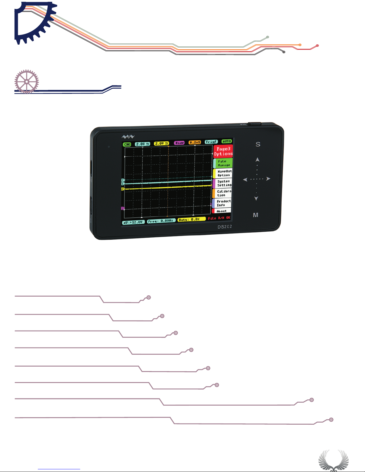
Page3( )option
File management
Output option
System settings
Adjusting option
Product information
relevant information
Annotation: detailed introduction to options refer to Page 13-18
Interface Introduction
Home screen introduction
Chapter 2
Option area introduction
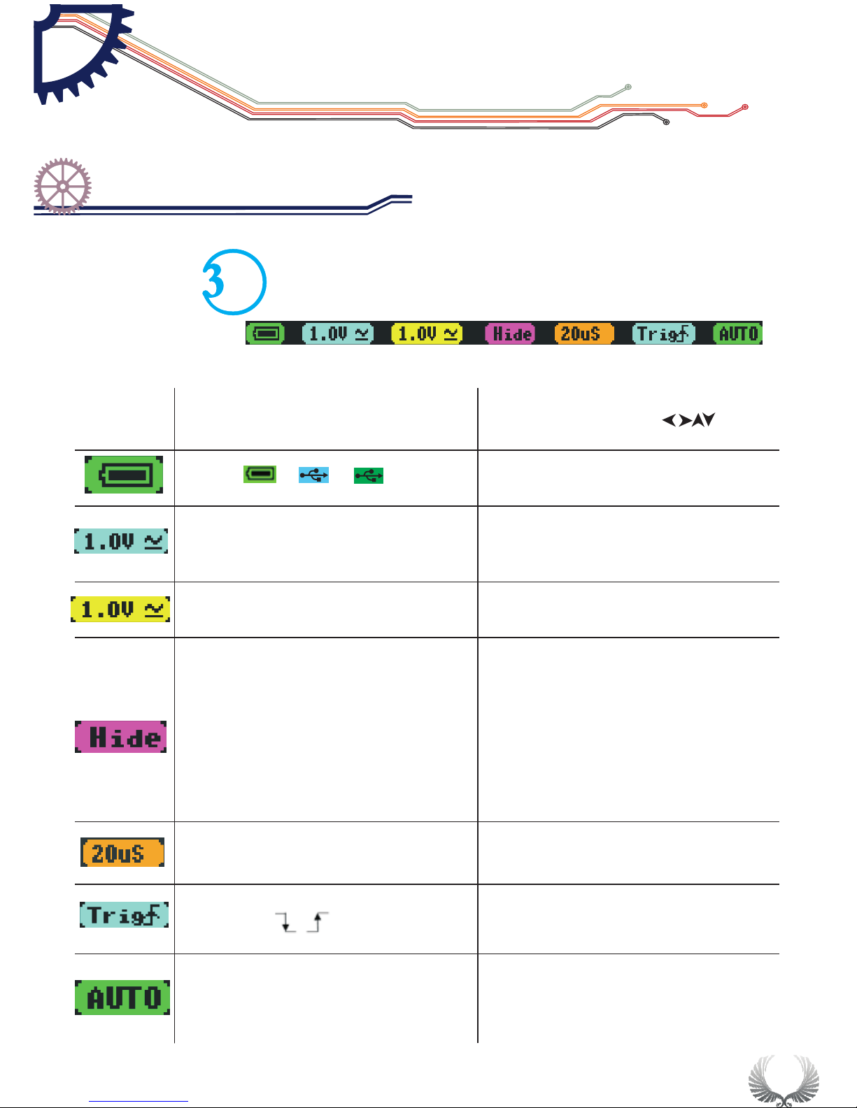
menu options
function(operation:press ,slide)
Battery supply/USB charging/full charge
/ /
20mV—10V(1-2-5 )
AC/DC
sequence step Channel A ordinate unit amplitude,
AC/ DC coupling method
20mV—10V(1-2-5 )
AC/DC
sequence step Channel B ordinate unit amplitude,
AC/ DC coupling method
(-A)/(-B)/(A+B)/(A-B)/
RecA/RecB/RecC
(-A):
(-B):
(A+B):
(A-B):
RecA:
RecB:
RecC:
channel A waveform reverse
channel B waveform reverse
addition of waveforms in channel A
and B
Subtraction of channel A waveform
and channel B waveform
Reload the previous saved waveform
in channel A
Reload the previous saved waveform
in channel B
RecC:Reload the previous saved
waveform in channel C
1.0uS—1S(1-2-5 )sequence step time unit value
Trigger mode:ascend/ descend trigger mode
AUTO/NORM/SINGL/NONE/SCANSTOP automatic/standard/single-pass/slow scan/immediate
scan/operation/pause
8
Interface Introduction
Home screen introduction
Chapter 2
Parameter area introduction

9
●Power On/Off Button
●In the shutdown state,press on Power Button" " for
approximately 2 seconds to start normally
Starting up
The default enter
into APP1
Upgrading/
Upgrade mode
●Press and hold Power button" "for approximately 4
seconds to enter into DFU mode
Forced Shut
Down
●Press“ ”Run/Pause”button to Power On and enter
APP2( if APP2 is not installed, then enter the DFU mode)
●In the Power On state, press Power button“ ”for
approximately 2 seconds to pop-up “Power Off” menu,
according Icon operation Choose Power Off. (In the
Power On state, long press“ ”Power button for 8
seconds to force Shut Down.)
||
Start Guide
Power On/Off
Chapter 3

Connect probes to both the MCX and CHA input jacks
Adjust relevant parameters of CH A:
Adjust the DC mode in AC/DC function in CH A
Voltage adjustment: adjust probe X1 to 1V, adjust probe X10 to 0.1V
1.
2.
Measure WAVE OUT outlet waveform
10
Start Guide
Check up before use
Chapter 3
11
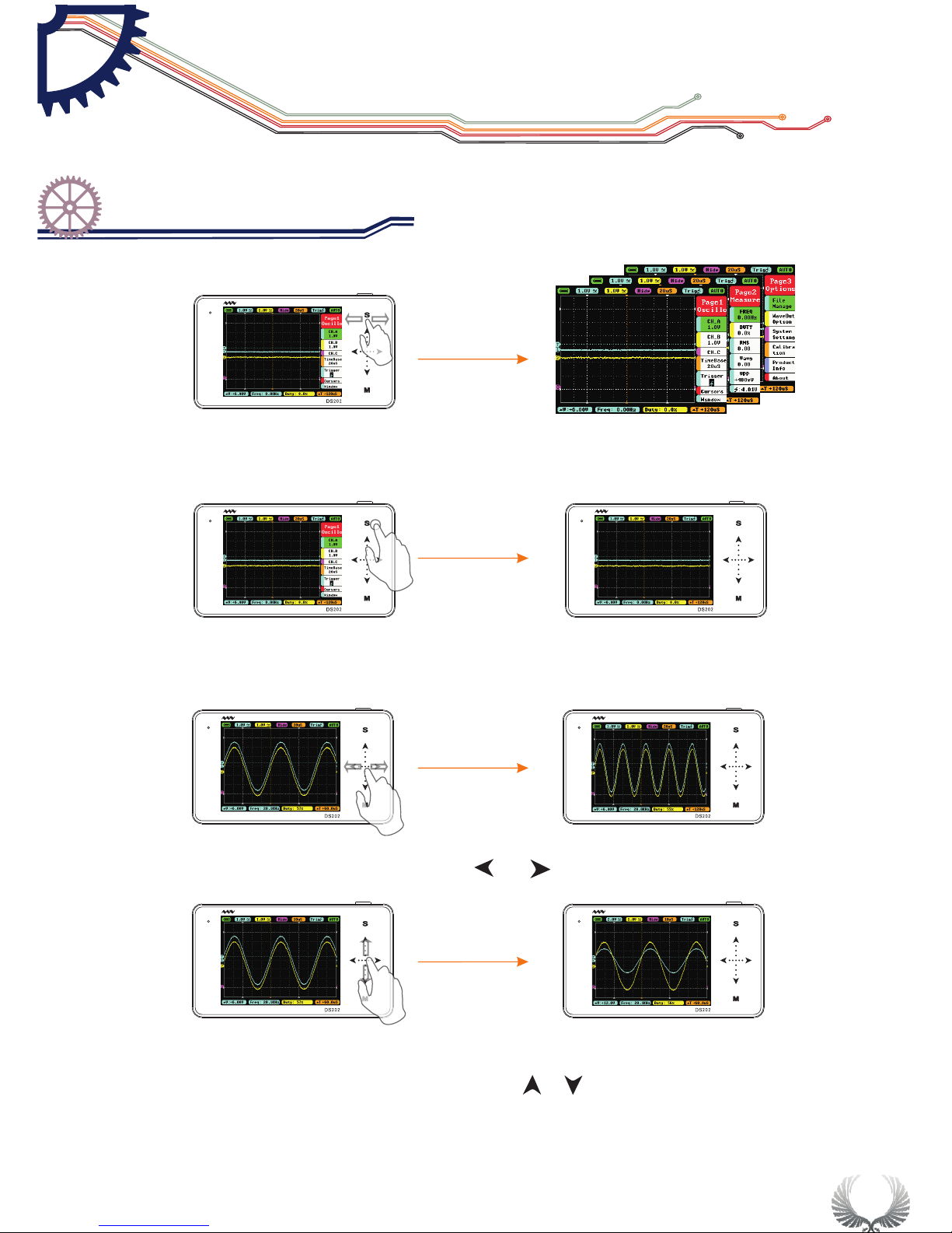
In the Main Menu interface, you can switch between the Main Menu pages by
sliding horizontally on the upper Touchpad.
In the Main Menu interface, tap “S” button to switch the Main Menu Display/ Hide
When the Main Menu is hidden, you can slide ••• horizontally to change the TimeBase
When the Main Menu is hidden, you can slide ··· vertically to change voltage
(shortcut for Channel A only)
Start Guide
Operation introduction
Chapter 3

12
In the Main Menu interface, tap “M” button to switch the Sub-menu to Display/Hide
In the Sub-menu interface, tap “S” button to confirm the selection of operation
In the Main Menu or Sub-menu interface, tap " "" "or" "" "slide vertically
to select items upward or downward
In the Main Menu or Sub-menu interface, tap" "" "or" "" "slide horizontally
to adjust the Menu parameters( When you move Positions in Sub-menu interface,
tap and hold your finger for continuous operation)
Start Guide
Operation introduction
Chapter 3

13
In the Main Menu or Sub-menu interface,tap and hold an non-button identification
area to Display/Hide file management sub-menu
When you turn on “Auto Fit” in “Trigger”, double-tap the non-button identification
area, the device will adjust automatically the amplitude, the time base and the trigger grid.
In the System Setting interface, when “PostSlide” is ON, slide up/down vertically the
touchpad in the left to adjust the position.
Start Guide
Operation introduction
Chapter 3
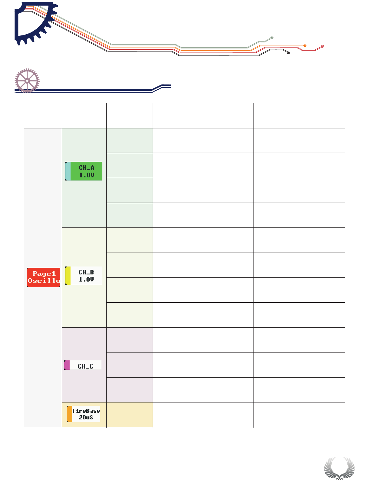
Voltage
Channel A y-axis voltage
per grid
20mV/50mV/0.1V/0.2V/0.5V/
1.0V/2.0V/5.0V/10V
Post
Adjust Channel A waveform position
upward/downward in the window
Position:5-195
AC/DC
channel A coupling
AD/DC
Enable
channel A display/hide
ON/OFF
Voltage
Channel B y-axis
voltage per grid
20mV/50mV/0.1V/0.2V/0.5
V/1.0V/2.0V/5.0V/10V
Post
Adjust Channel B waveform position
upward/downward in the window
Position:5-195
AC/DC
channel B coupling
AD/DC
Enable
channel B display/hide
ON/OFF
Match
Calculation between CH_A
waveform and CH_B waveform
–A,-B,A+B,A-
B,RecA,RecB,RecC
Post
Adjust CH_C waveform position
upward/downward in the window
Position:5-195
Enable
CH_C display / hide
ON/OFF
TimeBase
TimeBase X-axis
voltage per grid
1.0us-2.0s(1-2-5 )step
Menu Options Functions Annotation for functions Options for function
and annotation
Page1
Oscillo
14
Basic Function
Specific Parameter Intro
Chapter 4
15
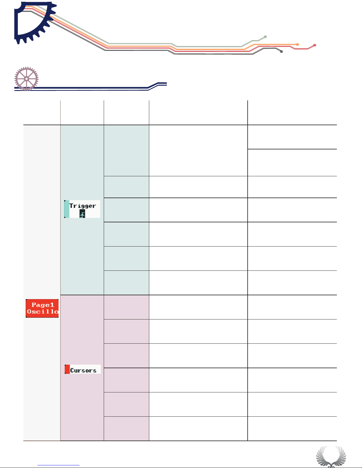
Syncmode
Selection for
synchronous mode
AUTO/NORM/SINGL/
NONE/SCAN
Automatic /standard /
single pass /slow scan/
immediate scan
Trigmode
Selection for trigger mode
Rising/falling edge
Source
Selection for
trigger channel
CHA/CHB
Threshol
Horizontal Triggering
Position Level
Position:5-198
Enable
Display/Hide Horizontal
Triggering Position Level
ON/OFF
Auto Fit
Automatic adjustment
ON/OFF
T1.Post
Time measurement
cursorT1
Position:5-248
T2.Post
Time measurement
cursor T2
Position:5-248
Enable.T
Show/hide Time
measurement cursor
ON/OFF
V1.Post
voltage measurement
cursor V1
Site selection:5-198
V2.Post
voltage measurement
cursor V2
Site selection:5-198
Enable.V
Show/hide voltage
measurement cursor
CHA/CHB/OFF
Page1
Oscillo
Menu options function Annotation for functions Options for function
and annotation
Basic Function
Specific Parameter Intro
Chapter 4
16
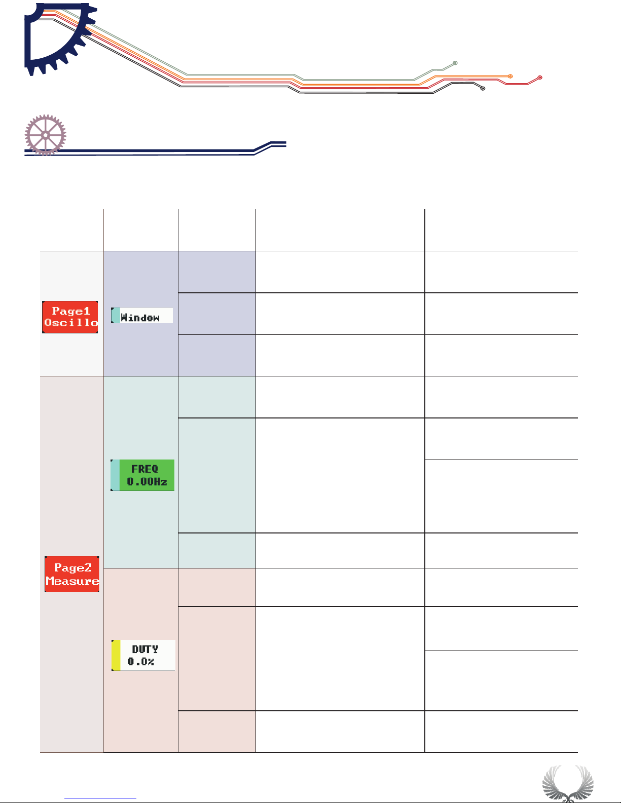
Post
Move horizontally
to check waveform
Select by storage depth
Depth
Internal storage depth
1k~8k
Enable
Show/hide event trigger
line vernier
ON/OFF
Source
Select measurement
channel
CHA/CHB
Type
Select measurement type
FREQ/DUTY/RMS/
Vavg/Vpp/Vmax/Vmin
Signal frequency/duty ratio,
effective voltage value
/average value/peak-to-peak
value/maximum
value/minimum value
Enable
Display/hide
measurement window
ON/OFF
Source
Select measurement
channel
CHA/CHB
Type
Select measurement type
FREQ/DUTY/RMS/
Vavg/Vpp/Vmax/ Vmin
Signal frequency/duty
ratio,effective voltage
value/average value/peak-to-
peak value/maximum
Enable
Display/hide
measurement window
ON/OFF
Page1
Oscillo
Menu item options Annotation for functions Options for function
and annotation
Page2
Measure
Basic Function
Specific Parameter Intro
Chapter 4

17
Source
Select measurement
channel
CHA/CHB
Type
Select measurement type
FREQ/ DUTY/ RMS/
Vavg/ Vpp/ Vmax/ Vmin
Signal frequency/duty ratio,effective
voltage value /average value/peak-to-
peak value/maximum
Enable
Display/hide
measurement window
ON/OFF
Source
Select measurement
channel
CHA/CHB
Type
Select measurement type
FREQ/ DUTY/ RMS/
Vavg/ Vpp/ Vmax/ Vmin
Signal frequency/duty ratio,effective
voltage value/average value/peak-to-
peak value/maximum
Enable
Display/hide
measurement window
ON/OFF
Source
Select measurement
channel
CHA/CHB
Type
Select measurement type
FREQ/ DUTY/ RMS/
Vavg/ Vpp/ Vmax/ Vmin
Signal frequency/duty ratio, effective
voltage value/average value/peak-to-
peak value/maximum
Enable
Display/hide
measurement window
ON/OFF
Vbat
Battery voltage
Menu options function Annotation for functions Options for function
and annotation
Page2
Measure
Basic Function
Specific Parameter Intro
Chapter 4
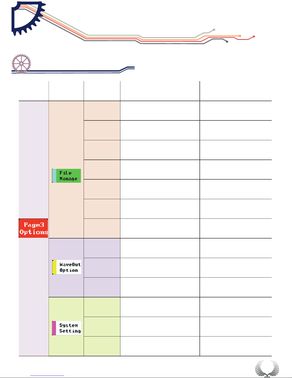
18
Save
Param
Save current
parameter settings
Tap “S”button to Save
Save Bmp
Save bmp file (waveform image) to
the built-in U disk.(Shortcut: long
press”Run/Pause”button
Tap “S”button to Save
Save Dat
Save dat file to built-in U
disk
Tap “S”button to Save
Save Buf
Save buf file (sampling data in
buffering area) to built-in U disk
Tap “S”button to Save
Save Csv
Save csv file (export sampling data in
buffering area) to built-in U disk
Tap “S”button to Save
Load Dat
Load dat file
Tap “S”buttonLoad files
Load Buf
Load buf file
Tap “S”buttonLoad files
Type
Output signal type
squar/sine/triangle
/sawtooth
Freq
Output signal frequecy
Duty
Output signal duty cycle
10%-90%
Volume
Adjust buzzer volume
0%-90%
Blight
Adjust backlight brightness
10%-100%
Standby
Adjust standby time
0min-30min
Menu options function Annotation for functions Options for function
and annotation
Page3
Setting
Squar(10Hz-1Mhz)sine/
triangle/sawtooth(10Hz-20kHz)
Basic Function
Specific Parameter Intro
Chapter 4
Table of contents
Other Min Test Equipment manuals


