Agatec RL110 User manual

User manual

2
User Manual
English
urchase
Congratulations on the purchase of a new Rotating Laser from Agatec.
roduct
This manual contains important safety directions as well
as instructions for setting up the product and operating it.
Refer to "Safety Directions" for further
information.
Read carefully through the User Manual before you switch on the product.
Symbols
The symbols used in this manual have the following meanings:
DANGER
Indicates an imminently hazardous situation which, if not avoided, will
result in death or serious injury.
WARNING
Indicates a potentially hazardous situation or an unintended use which, if
not avoided, could result in death or serious injury.
CAUTION
Indicates a potentially hazardous situation or an unintended use which, if
not avoided, may result in minor or moderate injury and / or appreciable
material, financial and environmental damage.
Introduction

3
Introduction 2
Features
Laser Overview {A}
Keypad Overview {B}
Basic Operation 6
How to use your Agatec RL110
Button Functions
Automatic / Manual modes
H.I. Alert mode
Rotation mode
Scanning mode
Wall Mount
Set-up manual slopes
Accessories 9
Remote Control
Receiver/Remote Control
Receiver
Other accessories
Batteries 10
Low battery Indicator
Replacing alkaline batteries
Check and Adjust 11
Notes and Responsibilities
Checking level accuracy
Checking vertical accuracy
Adjusting level accuracy (X, Y, Z axis)
Troubleshooting 15
Care and Transport 16
Transport
Storage
Cleaning and Drying
Safety Directions 17
eneral
Intended Use
Limits of Use
Responsibilities
Hazards of Use
Laser Classification
Electromagnetic Compatibility (EMC)
FCC Statement, Applicable in U.S.
International Limited Warranty 25
Technical Data 26
Contents

4
Features
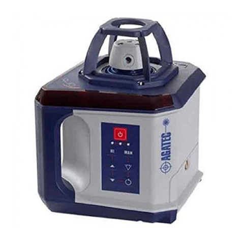
The Agatec RL110 laser offers the interior contractor many great features
to make work easier and more accurate.
A complete laser, with all needed functions, a bright beam for
high visibility, with very compact dimensions.
Laser Overview {A}
See the inside front cover for a diagram of the laser {A} and keypad {B}
corresponding to these callouts.
1) Rotating head
2) Axes indications
3) Plumb or square beam laser beam aperture
4) Rotating laser beam aperture
5) Batteries
6) 5/8"-11 Tripod mount for horizontal setup
Keypad Overview {B}
The keypad for the Agatec RL110 laser has seven buttons and three LED
indicators.
1) On / Off
2) H.I. (Elevation) Alert
3) UP
4) DOWN
5) Rotation Mode
6) Scan
7) Manual Mode
8) LED – H I indication
9) LED – Level Status / Battery
10) LED – Manual mode indication

5
14
5
6
2 3
Keypad Overview {B}
Laser Overview {A}
2 7
8
1
10
9
36
45

6
How to use your Agatec RL110
Horizontal Setup
The laser can be mounted on a 5/8"-11 tripod or placed directly on a
solid, stable surface. Agatec RL110 can be suspended from a ceiling
grid using the wall mount.
Vertical Setup
The laser can be placed directly on its back (opposite the handle) on a
solid, stable surface. For more stability, it is recommended to use the wall
mount.
Turning on the laser
Turn on the laser with the On/Off key {B-1}. It does a self-test and the
beam blinks while the laser is self- leveling. After it is leveled, the head
rotates. You can choose H.I. Alert mode or change to manual mode (see
later sections).
The laser has a wide self-leveling range; however, if the laser is set up out
of the leveling range, the laser beam will continue to blink and the
rotation will not start.
LED indication
The LED indicator {B-9} slowly blinks green and red while the axes
are leveling and stays on when both axis has reached a level position.
Button Functions
The UP/DOWN buttons on the laser and the remote control buttons have
multiple functions depending on the mode of operation. Please refer to the
chart below to better understand their functionality.
Basic Operation

7
Mode RIGHT / LEFT U / DOWN
Automatic mode - Moves CW/CCW Cycle through the
rotating mode rotating speed
Automatic mode - Moves scan Cycle through the
scanning CW/CCW scanning width
Laydown mode - Slope Cycle through the
rotating rotating speed
Laydown mode - Slope Cycle through the
scanning scanning width
Manual mode - Slope Cycle through the
rotating rotating speed
Manual mode - Slope Cycle through the
scanning scanning width
Automatic / Manual modes
The Agatec RL110 is in automatic, self-leveling mode when turned on.
Once the instrument has self-leveled, the laser head will start rotating with
600 rpm.
In manual mode, the laser does not self-level; this means that the
beam will rotate even if the laser is not leveled. It can therefore be
used on inclined planes such as stairs, roofs, or when manual grade
setting is required. See later section on setting slope in manual or
semi-automatic modes.
H.I. Alert mode
The H.I. feature stops the laser automatically if the laser is disturbed,
preventing inaccurate readings. It functions only when activated.
• To activate this safeguard feature, keep pressed the H.I. key {B-2} after
turning on the laser. The H.I. LED {B-8} will blink rapidly while the laser
is initializing the H.I. mode.

8
• Thirty seconds later, the LED will blink slowly, indicating the H.I. Alert
function is activated.
• If the laser is disturbed while in H.I. Alert mode, the head will stop
rotating, the beam will turn off, all LEDs will blink red.
• Press the ON/Off key to turn off the H.I. Alert function. Press again the
ON/OFF key to have the unit going back to the default settings (600 rpm,
automatic mode).
Rotation mode
The head rotates at three speeds: 0, 300, 450, 600 rpm. The default setting
is 600 rpm. The laser beam is more visible at slower rotation speeds.
• To cycle through the rotation speeds press the key {B-5}. Press once
to get to point mode, twice to 300 rpm, three times to get to 450 rpm.
One more time to get back to 600 rpm.
• When in point mode, the point can be moved to the right or left using
the UP/DOWN keys {B-3 and B-4}. It is also possible to move the head
manually to position the beam point.
To start rotation again, press the key {B-5}.
Scanning mode
For interior applications, scanning mode allows you to see the beam
easier at a distance.
The default width has medium dimension. The laser beam is more visible
at small width.
• To scan press the key {B-6}.
• To cycle through the scan width, press the key {B-6}.
• The scanning beam can be moved to the right or left using the
UP/DOWN keys {B-3 and B-4}.
Wall Mount
For interior application, such as drywall installation, it is recommended to
use the wall mount.
Use the tripod thread to fix the mount to the laser.

9
Set-up for manual slopes
The Agatec RL110 can be used to manually create slopes for special
applications, stairways, sloped ceilings, etc.
For slopes up to 10%, set up the laser in horizontal mode and use the
keypad or remote to set the slope following the instructions below.
In full manual mode, the unit will not self-level on both axis, meanwhile
the head will continue to rotate. The plane of laser light can be tilted in
either one or both planes.
To use the laser in full manual mode:
• After turning the laser on and allowing it to self-level, press the Manual
button {B-7}. The LED {B-10} indicates that the laser is in manual mode
and you can set slope in the X-axis.
• Press UP/DOWN keys to adjust the slope of the X-axis.
Press the Manual key {B-7} once more to set slope on Y-axis. The LED
{B-10} blinks to indicate that the laser is in manual mode and you can
set slope in the Y-axis.
Keep pressed the MAN key to exit the manual mode and return to the
automatic mode.
Accessories
Remote Control
The Remote Control has five buttons.
1) LEFT
2) RI HT
3) Scan / Rotation Mode
4) UP
5) DOWN
Please refer to the table in "Button Functions" to better understand their
functionality.
• The red LED at the top of the remote will flash each time a button is
pressed, indicating that the remote is transmitting to the laser.
• Battery - To open the battery compartment and change the battery,
push the battery cover in the direction of the arrow. The remote control
requires alkaline battery.
1
3
2
5
4

10
Other accessories
• Laser enhancing glasses improve the visibility of the laser beam in
bright light conditions.
• The ceiling grid targets are used to view the beam on suspended ceiling
applications. The target attaches magnetically to the grid.
Low battery Indicator
When the battery power is low, the LED {B-9} will blink red during
operation. Batteries have to be replaced as soon as possible. When
battery is empty, the laser head will stop rotating and the low battery
LED {B-9} will stay on.
Batteries
Receiver
The receiver indicates elevation information from rotating laser levels.
1) ower on/off
Press once to turn On.
Press and hold to turn off.
2) Audio
Select the sound level,
from Normal, Loud, Off.
3) Bandwidth
Cycle through detection accuracy,
from Normal, Fine.
1
2
3

11
Replacing alkaline batteries
Follow the steps below to replace the alkaline batteries in your laser.
• To access the battery compartment, loosen the knobs connecting the
laser to the wall mount.
• Use a coin or small screwdriver to remove the cover of the battery
compartment at the back of the laser.
• Insert two fresh alkaline batteries (D size or LR20), following the
polarization indicated at the bottom of the battery compartment. The plus
contact is rounded and raised. When replacing batteries, change both at
the same time.
• Replace the compartment and tighten with a coin or screwdriver.
Check and Adjust
Notes and Responsibilities
• It is the responsibility of the user to follow operating instructions and
to periodically check the accuracy of the instrument and work as it
progresses.
• The laser is adjusted to the defined accuracy specifications at the
factory. It is recommended to check your laser for accuracy upon receipt
and periodically thereafter to ensure accuracy is maintained. If your laser
requires adjustment, contact the nearest authorized service center.
• Accuracy adjustment should only be performed by a qualified
individual that understands basic adjustment principles.
Checking level accuracy
To check the level accuracy of your laser, place the unit on a flat, level
surface or tripod approximately 30 meters (100 ft.) from a wall.
• Align the X-axis so that it is square to the wall. Allow the laser to self-
level completely (approximately one minute after the laser begins to
rotate). Then mark the position of the beam (Position 1).

12
• Rotate the laser 180°, allow it to self level and mark the opposite side
of the first axis (Position 2).
• Align the Y-axis by rotating the laser 90° so that this axis is now square
to the wall. Allow the laser to self- level completely, and then mark the
position of the beam (Position 3).
• Rotate the laser 180°, allow it to self level and mark the opposite side
of the Y-axis (Position 4).
• The laser is within its accuracy specification if the four marks are
within ± 3 mm (± 1/8") from the center.
Checking vertical accuracy
To check the vertical accuracy of your laser, place the unit in the laydown
position on a flat, level surface approximately 15-30 meters (50-100 ft.)
from a wall.
• Hang a plumb line on the wall.
• Move the laser until the vertical, rotating beam is aligned to the plumb line.
• If the rotating beam is not plumb, adjustment is necessary.
Adjusting level accuracy -
The X-axis
After checking the accuracy of your laser, perform the following steps to
adjust the accuracy of the X-axis.
Turn off the laser.
• Press and hold the H.I. key {B-2}, then press the ON/OFF key {B-1}.
• After the three LEDs blink three times simultaneously, release the H.I. key.
- The X-axis LED will flash rapidly (red) while leveling
- The X-axis LED will flash slowly (red) when ready for adjustment.
- The head will not be rotating.
- Press the Scan/Rotation key {C-3} to start rotation mode.

13
• Press a UP/DOWN Key {C-4 or C-5} to adjust the beam up or down. Five
presses of the key will move the beam approximately 0.75 mm at 30 meters
(1/32" at 100 feet).
After completing the changes to the X-axis, do one of the following steps:
• Press the Right key {C-2} after completing adjustment to switch to the Y-axis.
• Press the Left key {C-1} to exit adjustment mode, save changes and turn
off the laser.
• Press the ON/OFF key {B-1} at any time to turn off the laser without
saving any changes.
Adjusting level accuracy -
The Y-axis
After checking the accuracy of your laser, perform the following steps to
adjust the accuracy of the Y-axis.
• If already in adjustment mode for the X-axis, press the Right key {C-2}
to switch to the adjustment of the Y-axis.
• If not in adjustment mode, follow the steps above for entering adjust-
ment mode, then press the Right key {C-2} to switch to the adjustment of
the Y-axis.
- The Y-axis LED will flash rapidly (red) while leveling
- The Y-axis LED will flash slowly (red) when ready for adjustment.
- The head will not be rotating.
- Press the Scan/Rotation key {B-5} to start rotation mode.
• Press a UP/DOWN Key {C-4 or C-5} to adjust the beam up or down.
Five presses of the key will move the beam approximately 0.75 mm at
30 meters (1/32" at 100 feet).
After completing the changes to the Y-axis, do one of the following steps:
• Press the Left key {C-1} to exit adjustment mode, save changes and turn
off the laser.
• Press the ON/OFF key {B-1} at any time to turn off the laser without
saving any changes.

14
Adjusting level accuracy -
The Z-axis
After checking the accuracy of your laser, perform the following steps to
adjust the accuracy of the Z-axis.
• Turn off the laser.
• Place the laser in the laydown position approximately 6 meters (20 feet)
from a plumb line on a wall.
• Press and hold the H.I. Alert key {B-2}, then press the ON/OFF key
{B-1}.
• After the three LEDs blink three times simultaneously, release the H.I. key.
- The Z-axis (Y-axis) LED will flash rapidly (red) while leveling
- The Z-axis (Y-axis) LED will flash slowly (red) when ready
for adjustment.
- The head will not be rotating.
- Press the Scan/Rotation key {C-3} to start rotation mode.
• Press a UP/DOWN Key {C-4 or C-5} to adjust the beam to the
plumb line.
After completing the changes to the Z-axis, do one of the following steps:
• Press the Left key {C-1} to exit adjustment mode, save changes and turn
off the laser.
• Press the ON/OFF key {B-1} at any time to turn off the laser without
saving any changes.
CHECK YOUR WORK
After any accuracy adjustments al ays double check your
ork, by making a final check of the laser.

15
Troubleshooting
ossible Causes and Solutions
The unit is most likely out of its 10%
self-leveling range.
• Check your set up and re-level the
tripod if necessary.
• If this does not solve the problem,
the laser should be returned to an
authorized service center for service.
The symptom may be caused by low or
dead batteries.
• Check or change the batteries.
• If not the batteries, the laser should be
returned to an authorized service center
for service.
Dirt may be reducing the output of the
laser.
• Clean the windows of the laser and
receiver to improve distance.
• If not the windows, the laser should be
returned to an authorized service center
for service.
Check for proper operation of the remote.
• Check that the laser is turned on.
• The remote may be outside the usable
distance.
• Aim the remote more directly at the
laser for maximum distance.
• The remote’s battery may be low.
Check for proper operation of the receiver.
• The laser is not rotating. It is leveling or
in elevation alert.
• The laser is in scanning mode.
• The receiver may be outside the usable
distance.
• The receiver’s battery may be low.
The unit has been moved or pushed as HI
was active. Press ON/OFF to restart the unit.
Symptom
The laser beam blinks,
but the unit will not
self-level or rotate.
The laser does not turn on.
The laser’s distance is
reduced.
The IR Remote is not
working.
The laser’s receiver is not
functioning properly.
ALL three LED's are
flashing in sequence.

16
Transport
Transport in the field
When transporting the equipment in the field, always make sure that you
• either carry the product in its original transport container,
• or carry the tripod with its legs splayed across your shoulder, keeping
the attached product upright.
Transport in a road vehicle
Never carry the product loose in a road vehicle, as it can be affected by
shock and vibration. Always carry the product in its transport container
and secure it.
Shipping
When transporting the product by rail, air or sea, always use the
complete original Agatec packaging, transport container and cardboard
box, or its equivalent, to protect against shock and vibration.
Shipping, transport of batteries
When transporting or shipping batteries, the person in charge of the
product must ensure that the applicable national and international rules
and regulations are observed. Before transportation or shipping, contact
your local passenger or freight transport company.
Field Adjustment
After transport inspect the field adjustment parameters given in this user
manual before using the product.
Storage
roduct
Respect the temperature limits when storing the equipment, particularly in
summer if the equipment is inside a vehicle. Refer to "Technical Data" for
information about temperature limits.
Field Adjustment
After long periods of storage inspect the field adjustment parameters
given in this user manual before using the product.
Alkaline Batteries
If the equipment is to be stored for a long time, remove the alkaline
batteries from the product in order to avoid the danger of leakage.
Care and Transport

17
Cleaning and Drying
roduct and Accessories
• Blow dust off optical parts.
• Never touch the glass with your fingers.
• Use only a clean, soft, lint-free cloth for cleaning. If necessary, moisten
the cloth with water or pure alcohol.
• Do not use other liquids; these may attack the polymer components.
Damp Products
• Dry the product, the transport container, the foam inserts and the
accessories at a temperature not greater than 40°C / 104°F and clean them.
• Do not repack until everything is completely dry.
Damp roducts
• Dry the product, the transport container, the foam inserts and the acces-
sories at a temperature not greater than 40°C / 104°F and clean them.
• Do not repack until everything is completely dry.
General
Description
The following directions should enable the person responsible for the
product, and the person who actually uses the equipment, to anticipate
and avoid operational hazards.
The person responsible for the product must ensure that all users
understand these directions and adhere to them.
Intended Use
ermitted Use
• The instrument casts a horizontal laser plane for the purposes of
alignment.
• The unit can be set up on its own base plate, wall- mount or on a
tripod.
• The laser beam can be detected by means of a laser detector.
• This product is intended for indoor use and applica- tions.
Safety Directions

18
Adverse Use
• Use of the product without instruction.
• Use outside of the intended limits.
• Disabling safety systems.
• Removal of hazard notices.
• Opening the product using tools, for example screw- driver, unless
this is specifically permitted for certain functions.
• Modification or conversion of the product.
• Use after misappropriation.
• Use of products with obviously recognizable damages or defects.
• Use with accessories from other manufacturers without the prior
explicit approval of Agatec.
• Inadequate safeguards at the work site, for example when using on
or near roads.
• Deliberate dazzling of third parties.
• Controlling of machines, moving objects or similar monitoring application
without additional control and safety installations.
WARNING
Adverse use can lead to injury, malfunction and damage. It is the task
of the person responsible for the equipment to inform the user about
hazards and how to counteract them. The product is not to be operated
until the user has been instructed on how to work with it.
Limits of Use
Environment
Suitable for use in an atmosphere appropriate for permanent human
habitation: not suitable for use in aggressive or explosive environments.
DANGER
Local safety authorities and safety experts must be contacted before
working in hazardous areas, or in close proximity to electrical installations
or similar situations by the person in charge of the product.
Responsibilities
Manufacturer of the product
Agatec SAS - 60, route de Sartrouville - 78230 Le Pecq - France, hereinafter
referred to as Agatec, is responsible for supplying the product, including
the user manual and original accessories, in a completely safe condition.

19
Manufacturers of non Agatec accessories
The manufacturers of non Agatec accessories for the product are
responsible for developing, implementing and communicating safety concepts
for their products, and are also responsible for the effective- ness of those
safety concepts in combination with the Agatec product.
erson in charge of the product
The person in charge of the product has the following duties
• To understand the safety instructions on the product and the instructions
in the user manual.
• To be familiar with local regulations relating to safety and accident
prevention.
• To inform Agatec immediately if the product and the application
becomes unsafe.
WARNING
The person responsible for the product must ensure that it is used in accor-
dance with the instructions. This person is also accountable for the training
and the deployment of personnel who use the product and for the safety
of the equipment in use.
Hazards of Use
WARNING
The absence of instruction, or the inadequate imparting of instruction, can
lead to incorrect or adverse use, and can give rise to accidents with
far-reaching human, material, financial and environmental conse- quences.
recautions:
All users must follow the safety directions given by the manufacturer and
the directions of the person respon- sible for the product.
CAUTION
Watch out for erroneous measurement results if the product has been
dropped or has been misused, modified, stored for long periods or
transported.
recautions:
Periodically carry out test measurements and perform the field
adjustments indicated in the user manual, particularly after the product
has been subjected to abnormal use and before and after important
measurements.

20
DANGER
Because of the risk of electrocution, it is
very dangerous to use grade rods and
staffs in the vicinity of electrical installations such as power cables or
electrical railways.
recautions:
Keep at a safe distance from electrical installations. If it is essential to
work in this environment, first contact the safety authorities responsible for
the electrical installa- tions and follow their instructions.
WARNING
If the product is used with accessories, for example masts, staffs, poles,
you may increase the risk of being struck by lightning.
recautions:
Do not use the product in a thunderstorm.
WARNING
Inadequate securing of the working site can lead to dangerous situations,
for example in traffic, on building sites, and at industrial installations.
recautions:
Always ensure that the working site is adequately secured. Adhere to the
regulations governing safety and accident prevention and road traffic.
CAUTION
If the accessories used with the product are not properly secured and the
product is subjected to mechanical shock, for example blows or falling,
the product may be damaged or people may sustain injury.
recautions:
When setting-up the product, make sure that the accessories are correctly
adapted, fitted, secured, and locked in position. Avoid subjecting the
product to mechanical stress.
CAUTION
During the transport, shipping or disposal of batteries it is possible for
inappropriate mechanical influ- ences to constitute a fire hazard.
recautions:
Before shipping the product or disposing of it, discharge the batteries by
running the product until they are flat. When transporting or shipping bat-
teries, the person in charge of the product must ensure that the applica-
ble national and international rules and regulations are observed. Before
transportation or shipping contact your local passenger or freight
transport company.
WARNING
High mechanical stress, high ambient tempera- tures or immersion
into fluids can cause leackage, fire or explosions of the batteries.
Other manuals for RL110
1
Table of contents
Other Agatec Measuring Instrument manuals