AGCO Glencoe SS7600 Series User manual

Glencoe®
MODEL SS7600 SERIES
SOIL SAVER
OPERATOR’S
MANUAL
Form No. 79019153
December, 2001


MODEL SS7600 SERIES
SOIL SAVER
OPERATOR’S MANUAL
PURCHASED FROM: DATE / /
ADDRESS:
PHONE NO.: SERIAL NO.:


TABLE OF CONTENTS
SECTION DESCRIPTION PAGE NO.
1 INTRODUCTION 1-1
2 STANDARD SPECIFICATIONS 2-1
3 ASSEMBLY INSTRUCTIONS 3-1
3-1 SINGLE AXLE MODEL FRAME ASSEMBLY ................3-3
3-2 TANDEM AXLE MODEL FRAME ASSEMBLY................3-3
3-3 SINGLE AXLE MODEL ROCKSHAFT INSTALLATION .........3-5
3-4 TANDEM AXLE MODEL ROCKSHAFT INSTALLATION ........3-7
3-5 SINGLE AXLE MODEL HYDRAULIC PLUMBING INSTALLATION 3-9
3-6 TANDEM AXLE MODEL HYDRAULIC
PLUMBING INSTALLATION ............................3-11
3-7 PULL HITCH INSTALLATION...........................3-13
3-8 DISC GANG INSTALLATION ...........................3-15
3-9 DISC GANG HYDRAULIC ADJUSTMENT/INSTALLATION .....3-17
3-10 RIGID AND SPRING CLAMP INSTALLATION...............3-19
3-11 DECALS ..........................................3-20
3-12 WARNING LIGHTS INSTALLATION ......................3-21
3-13 LUBRICATION ......................................3-21
4 OPERATION AND MAINTENANCE 4-1
4-1 TRACTOR PREPARATION .............................4-2
4-2 SOIL SAVER PREPARATION ...........................4-2
4-3 ATTACHING TO THE TRACTOR .........................4-2
4-4 FIELD OPERATION ...................................4-3
4-5 WHEEL BEARING MAINTENANCE .......................4-4
4-6 LUBRICATION.......................................4-4
4-7 HYDRAULIC MAINTENANCE............................4-4
4-8 STORAGE..........................................4-4
5 TROUBLESHOOTING GUIDE 5-1
i

SAFETY PRECAUTIONS
THIS IS THE SAFETY ALERT SYMBOL. IT IS USED TO ALERT YOU
TO POTENTIAL INJURY HAZARDS. OBEY ALL SAFETY MES-
SAGES THAT FOLLOW THIS SYMBOL TO AVOID POSSIBLE IN-
JURY OR DEATH.
DANGER DANGER INDICATES AN IMMINENTLY HAZARDOUS SITUA-
TION WHICH, IF NOT AVOIDED, WILL RESULT IN DEATH OR
SERIOUS INJURY.
WARNING WARNING INDICATES A POTENTIALLY HAZARDOUS SITUA-
TION WHICH, IF NOT AVOIDED, COULD RESULT IN DEATH
OR SERIOUS INJURY.
CAUTION CAUTION INDICATES A POTENTIALLY HAZARDOUS SITUA-
TION WHICH, IF NOT AVOIDED, MAY RESULT IN MINOR OR
MODERATE INJURY.
CAUTION CAUTION USED WITHOUT THE SAFETY ALERT SYMBOL IN-
DICATES A POTENTIALLY HAZARDOUS SITUATION WHICH,
IF NOT AVOIDED, MAY RESULT IN PROPERTY DAMAGE.
ii

1INTRODUCTION
The SS7600 Series Soil Saver is a quality product designed to give years of trouble free performance.
By following each section of this manual, your system will perform as designed for you and your operation.
SECTION 1 gives basic instructions on the use of this manual.
SECTION 2 gives product specifications. These specifications supply lengths and measures for your
equipment. A Standard Bolt Torque Table is provided to give guidelines for bolt torques
to be used when servicing this product.
SECTION 3 contains assembly instructions for your SS7600 Series Soil Saver. When these proce-
dures are correctly followed, your equipment should provide you years of trouble-free
operation and service.
SECTION 4 instructs how to operate your equipment before using it, and describes adjustments
needed. It also gives practical advice for the care and maintenance of your equipment.
Drawings in this section locate adjustment points on the equipment.
SECTION 5 is a troubleshooting guide to aid in diagnosing and solving problems with the equip-
ment.
PARTS LIST is a separate manual showing the various assemblies, subassemblies, and systems.
Refer to that manual when ordering replacement parts. Order parts from your dealer.
WARRANTY The Warranty Registration form must be completed by the dealer and signed by both
the dealer and the custormer prior to delivery.
NOTE: IMPROPER ASSEMBLY, MODIFICATION, OR MAINTENANCE OF YOUR
MACHINE CAN VOID YOUR WARRANTY.
1-1

2STANDARD SPECIFICATIONS
MODEL
NUMBER
WORKING
WIDTH
TRANSPORT
WIDTH
(ft.-in.)
NO. OF
SHANKS
NO. OF
DISCS
WEIGHT
(APPROX.)
(lbs.)
SS7600-11 11-7 12-5" 7 28 7,520
SS7600-14 14-9 15-7 9 32 8,120
SS7600-16 16-5 17-3 11 36 8,600
SS7600-16 16-5 17-3" 11 36 10,440
SS7600-20 19-11 20-9 13 42 11,150
SS7600-19 21-7 22-5" 15 46 11,750
2-1

2-2
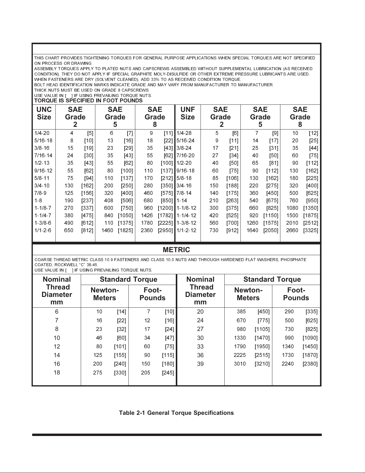
GENERAL TORQUE SPECIFICATIONS (REV. 4/97)
THIS CHART PROVIDES TIGHTENING TORQUES FOR GENERAL PURPOSE APPLICATIONS WHEN SPECIAL TORQUES ARE NOT SPECIFIED
ON PROCESS OR DRAWING.
ASSEMBLY TORQUES APPLY TO PLATED NUTS AND CAPSCREWS ASSEMBLED WITHOUT SUPPLEMENTAL LUBRICATION (AS RECEIVED
CONDITION). THEY DO NOT APPLY IF SPECIAL GRAPHITE MOLY-DISULFIDE OR OTHER EXTREME PRESSURE LUBRICANTS ARE USED.
WHEN FASTENERS ARE DRY (SOLVENT CLEANED), ADD 33% TO AS RECEIVED CONDITION TORQUE.
BOLT HEAD IDENTIFICATION MARKS INDICATE GRADE AND MAY VARY FROM MANUFACTURER TO MANUFACTURER.
THICK NUTS MUST BE USED ON GRADE 8 CAPSCREWS.
USE VALUE IN [ ] IF USING PREVAILING TORQUE NUTS.
TORQUE IS SPECIFIED IN FOOT POUNDS
UNC
Size
SAE
Grade
2
SAE
Grade
5
SAE
Grade
8
UNF
Size
SAE
Grade
2
SAE
Grade
5
SAE
Grade
8
1/4-20 4 [5] 6 [7] 9 [11] 1/4-28 5 [6] 7 [9] 10 [12]
5/16-18 8 [10] 13 [16] 18 [22] 5/16-24 9 [11] 14 [17] 20 [25]
3/8-16 15 [19] 23 [29] 35 [43] 3/8-24 17 [21] 25 [31] 35 [44]
7/16-14 24 [30] 35 [43] 55 [62] 7/16-20 27 [34] 40 [50] 60 [75]
1/2-13 35 [43] 55 [62] 80 [100] 1/2-20 40 [50] 65 [81] 90 [112]
9/16-12 55 [62] 80 [100] 110 [137] 9/16-18 60 [75] 90 [112] 130 [162]
5/8-11 75 [94] 110 [137] 170 [212] 5/8-18 85 [106] 130 [162] 180 [225]
3/4-10 130 [162] 200 [250] 280 [350] 3/4-16 150 [188] 220 [275] 320 [400]
7/8-9 125 [156] 320 [400] 460 [575] 7/8-14 140 [175] 360 [450] 500 [625]
1-8 190 [237] 408 [506] 680 [850] 1-14 210 [263] 540 [675] 760 [950]
1-1/8-7 270 [337] 600 [750] 960 [1200] 1-1/8-12 300 [375] 660 [825] 1080 [1350]
1-1/4-7 380 [475] 840 [1050] 1426 [1782] 1-1/4-12 420 [525] 920 [1150] 1500 [1875]
1-3/8-6 490 [612] 110 [1375] 1780 [2225] 1-3/8-12 560 [700] 1260 [1575] 2010 [2512]
1/1-2-6 650 [812] 1460 [1825] 2360 [2950] 1/1-2-12 730 [912] 1640 [2050] 2660 [3325]
METRIC
COARSE THREAD METRIC CLASS 10.9 FASTENERS AND CLASS 10.0 NUTS AND THROUGH HARDENED FLAT WASHERS, PHOSPHATE
COATED, ROCKWELL C 38-45.
USE VALUE IN [ ] IF USING PREVAILING TORQUE NUTS.
Nominal
Thread
Diameter
mm
Standard Torque Nominal
Thread
Diameter
mm
Standard Torque
Newton-
Meters
Foot-
Pounds
Newton-
Meters
Foot-
Pounds
6
10 [14] 7 [10]
20
385 [450] 290 [335]
7
16 [22] 12 [16]
24
670 [775] 500 [625]
8
23 [32] 17 [24]
27
980 [1105] 730 [825]
10
46 [60] 34 [47]
30
1330 [1470] 990 [1090]
12
80 [101] 60 [75]
33
1790 [1950] 1340 [1450]
14
125 [155] 90 [115]
36
2225 [2515] 1730 [1870]
16
200 [240] 150 [180]
39
3010 [3210] 2240 [2380]
18
275 [330] 205 [245]
Table 2-1 General Torque Specifications

2-3
HYDRAULIC FITTING TORQUE SPECIFICATIONS
37oJIC, ORS, & ORB (REV. 10/97)
THIS CHART PROVIDES TIGHTENING TORQUES FOR HYDRAULIC FITTING APPLICATIONS WHEN SPECIAL TORQUES ARE NOT SPECIFIED
ON PROCESS OR DRAWING.
ASSEMBLY TORQUES APPLY TO PLATED CARBON STEEL AND STAINLESS STEEL FITTINGS ASSEMBLED WITHOUT SUPPLEMENTAL
LUBRICATION (AS RECEIVED CONDITION).
THEY DO NOT APPLY IF SPECIAL GRAPHITE MOLY-DISULFIDE OR OTHER
EXTREME PRESSURE LUBRICANTS ARE USED.
BRASS FITTINGS AND ADAPTERS - 65% OF THE TORQUE VALUE FOR STEEL. STAINLESS STEEL,
ALUMINUM AND MONEL - THREADS ARE TO BE
LUBRICATED.
TORQUE IS SPECIFIED IN FOOT POUNDS
PARKER BRAND FITTINGS
Dash
Size
37 Degree
JIC
O-Ring
(ORS)
O-Ring Boss
(ORB)
-4 11-13 15-17 13-15
-5 14-16 — 21-23
-6 20-22 34-36 25-29
-8 43-47 58-62 40-44
-10 55-65 100-110 57.5-62.5
-12 80-90 134-146 75-85
-16 115-125 202-218 109-121
-20 160-180 248-272 213-237
-24 185-215 303-327 238-262
-32 250-290 — 310-340
HYDRAULIC FITTING TORQUE SPECIFICATIONS
37oJIC, ORS & ORB (REV. 10/97)
THIS CHART PROVIDES TIGHTENING TORQUES FOR HYDRAULIC FITTING APPLICATIONS WHEN SPECIAL TORQUES ARE NOT SPECIFIED
ON PROCESS OR DRAWING.
ASSEMBLY TORQUES APPLY TO PLATED CARBON STEEL AND STAINLESS STEEL FITTINGS ASSEMBLED WITHOUT SUPPLEMENTAL
LUBRICATION (AS RECEIVED CONDITION).
THEY DO NOT APPLY IF SPECIAL GRAPHITE MOLY-DISULFIDE OR OTHER
EXTREME PRESSURE LUBRICANTS ARE USED.
BRASS FITTINGS AND ADAPTERS - 65% OF THE TORQUE VALUE FOR STEEL.
TORQUE IS SPECIFIED IN FOOT POUNDS.
AEROQUIP BRAND FITTINGS
Dash
Size
37 Degree
JIC
O-Ring
(ORS)
O-Ring Boss
(ORB)
-4 11-12 10-12 14-16
-5 15-16 — 18-20
-6 18-20 18-20 24-26
-8 38-42 32-35 50-60
-10 57-62 46-50 72-80
-12 79-87 65-70 125-135
-14 — — 160-180
-16 108-113 92-100 200-220
-20 127-133 125-140 210-280
-24 158-167 150-165 270-360
-32 245-258 — —
Table 2-2 Hydraulic Fitting Torque Specifications

NOTES:
2-4

2-5
Figure 2-1 Single Axle, 28 Disc, 7 Shank Spacing

2-6
Figure 2-2 Single Axle, 32 Disc, 9 Shank Spacing

2-7
Figure 2-3 Single Axle, 36 Disc, 11 Shank Spacing

2-8
Figure 2-4 Tandem Axle, 36 Disc, 11 Shank Spacing

2-9
Figure 2-5 Tandem Axle, 42 Disc, 13 Shank Spacing

2-10
Figure 2-6 Tandem Axle, 46 Disc, 15 Shank Spacing

3ASSEMBLY INSTRUCTIONS
It is very important that your new SS7600 Se-
ries Soil Saver be properly assembled, adjusted
and lubricated before use. Illustrations to assist
with the assembly process are provided in Section
2, “Standard Specifications”. They show proper
shank, disc gang and mounting bracket spacings.
Illustrations in this section show proper assembly
procedures. Remove paint from grease fittings. Re-
place any grease fittings that are damaged or
missing. Be sure to return bolts, clips, etc., to their
original locations.
To insure alignment of assemblies, leave the
nuts loose until completion of final assembly.
Use lock washers or flatwashers as specified.
Spread all cotter pins.
After completion of final assembly, tighten all
nuts evenly to prevent misalignment, distortion or
binding. Tighten all bolts and nuts to the recom-
mended torques shown in Table 2-1, “Standard
Bolt Torques”.
DANGER
DISC BLADES ARE EXTREMELY
SHARP. EXERCISE EXTREME CARE
WHEN WORKING ON OR NEAR DISC
BLADES. DO NOT ALLOW DISCS TO
ROLL OVER OR FALL ONTO ANY BOD-
ILY PART. DO NOT ALLOW
WRENCHES TO SLIP WHEN WORKING
NEAR DISC BLADES. NEVER PUSH
WRENCHES TOWARD DISC BLADES.
DO NOT CLIMB OVER MACHINE
ABOVE DISC BLADES. FAILURE TO
STAY CLEAR OF DISC BLADE EDGES
CAN CAUSE SERIOUS PERSONAL IN-
JURY OR DEATH.
CAUTION
INCORRECT ADJUSTMENT OF DISC
ADJUST RODS WILL CAUSE PERMA-
NENT EQUIPMENT DAMAGE.
WARNING
DO NOT ATTEMPT TO LIFT HEAVY
PARTS (SUCH AS THE FRAME, DISC
GANGS, ROCK SHAFT, AND PULL
HITCH) MANUALLY. USE A HOIST OR
A FORK LIFT TO MOVE THESE PARTS
INTO POSITION.
DANGER
TO PREVENT ACCIDENTAL LOWER-
ING:
1. ALL HYDRAULICALLY ELEVATED
EQUIPMENT MUST BE LOCKED OUT
USING THE CYLINDER LOCKOUTS:
2. LOWER EQUIPMENT TO THE
GROUND WHILE SERVICING OR
WHEN IT IS IDLE.
FAILURE TO TAKE MEASURES TO
PREVENT ACCIDENTAL LOWERING
MAY RESULT IN SERIOUS PERSONAL
INJURY OR DEATH.
CAUTION
BE SURE DEPTH STOPS ARE EQUAL
LENGTHS ON ALL CYLINDERS. USING
UNEQUAL DEPTH STOP LENGTHS
CAN CAUSE PERMANENT EQUIP-
MENT DAMAGE.
CAUTION
BE SURE TO BLEED THE HYDRAULIC
SYSTEM OF ALL AIR IN LINES AFTER
INSTALLATION. FAILURE TO BLEED
THE SYSTEM OF ALL AIR CAN RE-
SULT IN IMPROPER MACHINE OPERA-
TION.
3-1

3-2
Figure 3-1 Tandem Axle Frame Assembly

3-1 SINGLE AXLE MODEL FRAME ASSEMBLY
No assembly is needed for the single axle
model frame. However, it needs to be placed on
stands about 36" high in an open, level area. If
your Soil Saver is equipped with frame extensions,
see Section 3-2.4 and 3-2.5 for their proper in-
stallation procedures.
3-2 TANDEM AXLE MODEL FRAME ASSEMBLY
WARNING
TO PREVENT SERIOUS INJURY OR
DEATH, READ ALL SAFETY PRECAU-
TIONS AT THE FRONT OF THIS SEC-
TION BEFORE ATTEMPTING ANY OF
THE FOLLOWING PROCEDURES.
IMPORTANT
SEE FIGURE 3-1 FOR PART NAMES.
3-2.1 Place both frame halves on stands about
36" high in an open, level area.
a. Use 3/4" x 2-1/2" cap screws and 3/4" lock-
ing nuts in the tube plates
b. Use 3/4" x 6-1/2" cap screws with locking
nuts in the mast plates.
c. Install bushing on rear top mast capscrew
and bushing with front leveler link on front top
capscrew.
IMPORTANT
LONG ARM OF LEVELER SHOULD BE DOWN
WITH GREASE ZERK FACING FORWARD. (SEE
FIGURE 3-8)
CAUTION
FRONT LEVELING LINKAGE MUST BE
INSTALLED ON FRONT MAST PLATE
BOLT OR DAMAGE WILL OCCUR DUR-
ING OPERATION.
d. Bolt the two halves together. Leave all bolts
loose, initially.
3-2.2 Level the frame halves.
3-2.3 Tighten all connecting bolts to the torques
listed in Table 2-1, “Standard Bolt
Torques”.
IMPORTANT
BE SURE TO TIGHTEN THE TOP AND BOTTOM
BOLTS EQUALLY.
3-2.4 Mark the spacing for shank mounts on the
tool bars. See Figures 2-1 through 2-6 for
their proper locations.
3-2.5 FRAME EXTENSIONS: If your SS7600
Soil Saver needs frame extensions to add
extra shanks:
a. Install the extensions by securing them to
the plates provided on the sides of the
frames. Use cap screws and locking nuts to
secure the plates.
b. Secure the braces on the long frame exten-
sions to the frame with U-bolts and locking
nuts.
3-3
This manual suits for next models
5
Table of contents