TESTa n DRaIn®Va l V E RE p a I R KI T TESTa n DRaIn®Va l V E RE p a I R KI T
A A
B B
D D
C C
D D
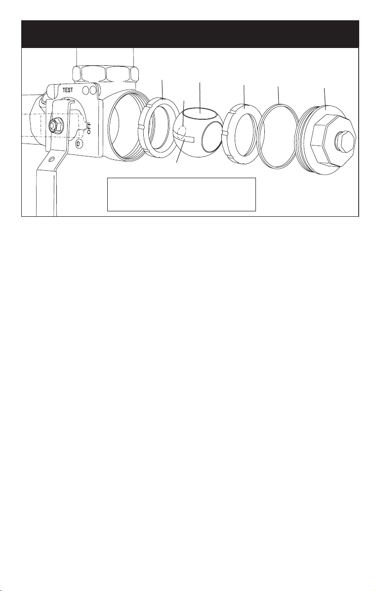
Repair Kit Includes: (1) adapter gasket (B), (1) ball (C), (2) valve seats (D), (1) stem
packing (not shown, see Note 1) and (1) stem washer (not shown, see Note 1).
READ ALL INSTRUCTIONS COMPLETELY AND FAMILIARIZE YOURSELF WITH
THE PROCEDURE PRIOR TO PERFORMING ANY REPAIR.
Repair Instructions
The following repair instructions are intended to be followed in whole for the repair of
1¼" – 2" valve models. For the repair of ¾" – 1" valve models see additional Note 2
below.
1. Close the sectional control/isolation valve to the section of piping connected to the
TESTa n DRaIn®valve that is to be repaired.
2. After the piping is isolated, open the TESTa n DRaIn®valve to the “DRAIN” position
and allow the isolated section of piping to drain completely.
3. Remove the adapter (A) of the TESTa n DRaIn®valve by turning the adapter coun-
terclockwise.
4. Remove the first valve seat (D), known as the upstream valve seat, and discard.
5. For 1¼" – 2" valve models, remove the adapter gasket (B) and discard. For ¾" – 1"
valve models see Note 2a.
6. Turn the TESTa n DRaIn®handle to the “TEST” position. Remove the ball (C).
7. Remove the second valve seat (D), known as the downstream valve seat, and dis-
card. The use of a small tack puller may be required to pull out the downstream
valve seat. Take care not to mar the surface of the valve seat shoulder.
8. Flush all debris from the inside of valve body with clear water and wipe clean.
9. Insert (1) new valve seat (D), flat side first, so the flat side of the valve seat rests flush
with the flat surface of the valve seat shoulder. To avoid damage to the valve seats,
DO NOT USE ANY TOOLS TO INSTALL THE VALVE SEATS.
10. The new ball (C) is sent lubricated, DO NOT REMOVE BALL LUBRICATION. To
insert the new ball (C) orient the ball as follows while maintaining the valve handle
in the “TEST” position:
INST-RepairKit INST-RepairKit
Ball must be inserted into valve with keyway
slot perpendicular to valve handle in “TEST”
position and test orifice facing the valve’s outlet.
Ball must be inserted into valve with keyway
slot perpendicular to valve handle in “TEST”
position and test orifice facing the valve’s outlet.
test
orifice
test
orifice
keyway slot keyway slot