AGF COLLECTanDRAIN 5450 User manual

1
Model 5450
Owner’s Manual
INST-5450 · 9/21
AGF Manufacturing Inc.

AGF Manufacturing Inc.
100 Quaker Lane • Malvern, PA 19355
www.agfmfg.com
AGF Manufacturing Inc.
TABLE OF CONTENTS
Introduction.......................................................................................3
Installation Instructions ............................................................... 4-7
Unpacking.........................................................................................4
Sprinkler System Preparation...........................................................4
Mounting...........................................................................................4
Wiring................................................................................................5
Verify Correct Operation ............................................................... 6-7
Operating Instructions ................................................................. 7-9
To Collect Condensate .....................................................................8
To Drain Condensate .................................................................... 8-9
Maintenance Instructions.......................................................... 9-11
Verify Alarm Operation......................................................................9
Inspect Y-Strainer Screen........................................................... 9-10
Verify Heater Operation (M5450) ....................................................10
Verify Heater and HOT Monitor Operation (M5450H) ............... 10-11
Change Timer Setting (M5450H) ....................................................11
Change Thermostat Setting............................................................11

AGF Manufacturing Inc. • Phone: 610-240-4900 • Fax: 610-240-4906 • www.agfmfg.com 3
Model 5450 COLLECTanDRAIN®Owner’s Manual
Model 5450 COLLECTanDRAIN
The COLLECTanDRAIN Model 5450 is a heated and insulated auxiliary drain (con-
densate collection assembly/drum drip/low-point drain) with Drain Trap, Float
Switch, and Alarm for dry pipe sprinkler systems. The M5450 is designed for
installation in climates where freezing or below freezing temperatures are present
and result in the failure of typical collection assemblies. The M5450 maintains a
comfortable temperature above freezing while minimizing power consumption.
CAUTION: The heater and its deector bracket may be hot. Use care when
accessing the main cabinet for any reason.
System Supply Pipe
System Supply Valve
Electrical Connection
“TEST” Button
Alarm Light
System Drain Valve
Float Switch
Drain Trap
Drain Trap Drain Pipe
Y-Strainer
System Drain Pipe
Heater
Drain Pipe Cap

Model 5450 COLLECTanDRAIN®Owner’s Manual
4
INSTALLATION INSTRUCTIONS
Unpacking:
1. Unpack the COLLECTanDRAIN M5450 unit and carefully inspect for any
damages from shipping.
2. Verify box contents:
• COLLECTanDRAIN M5450 unit
• Four (4) Rubber Mounting Washers
• Two (2) Door Keys
• Electrical Wiring Schematic
• M5450 System Drawing
Sprinkler System Preparation:
If installing in a new system, proceed to Mounting Instruction below, otherwise
continue with Sprinkler System Preparation.
If adding additional installations, see NFPA 13, chapters 24 and 26; and NFPA 25,
chapter 14.
1. Isolate the zone where the COLLECTanDRAIN will be installed.
2. Relieve air pressure from the branch line.
3. Remove the existing auxiliary drain.
Mounting:
Use the mounting tabs (4 – 3/8” holes) to mount the M5450 to a wall or other
structure. If wall is uneven use bushings or stand-offs to prevent cabinet from
bending when mounting.
1. Place the (4) Rubber Mounting Washers
behind the mounting tabs to hold the M5450
off the wall. Select fasteners (not provided)
capable of supporting the 55 lb. weight of the
M5450.
2. Connect to the 1” NPT supply pipe in
accordance with NFPA 13 regarding low-point
drain installations.
3. Connect the ½” NPT Drain Trap pipe to
suitable drain plumbing capable of accepting
the discharge and directing it to a drain
connection or other safe location in order to
avoid a potential slip and fall situation. The
use of an Air Gap is recommended.

AGF Manufacturing Inc. • Phone: 610-240-4900 • Fax: 610-240-4906 • www.agfmfg.com 5
Wiring:
The M5450 is protected internally by a 3A circuit breaker and requires
a 120VAC power source. Ensure the breaker in the main panel is sized
appropriately. Refer to the image below that coincides with your model.
1. Run conduit to the 1/2” connection on the top of the unit.
2. Open the door using the supplied keys.
3. Loosen the four screws on the front of the M5450 Alarm Panel and carefully
remove the door.
4. Run a single set of appropriately sized power wires into the Alarm Panel (Refer
to the electrical schematic as necessary).
NOTE: Use dedicated junction boxes (not provided) to make wire connections
when installing more than one M5450 on a circuit.
5. Connect the 120VAC hot wire to the circuit breaker.
6. Connect the 120VAC neutral wire to one of the neutral terminals.
7. Connect the ground wire to the green/yellow ground terminal.
The M5450 can be connected to a Remote Panel. This is accomplished through a
set of N.O. (close on alarm) auxiliary contacts.
1. Run two additional wires into the M5450 Alarm Panel.
2. Connect one wire to the AC1 (auxiliary contact) terminal.
3. Connect the other wire to the AC2 (auxiliary contact) terminal.
4. Connect these wires to the appropriate place in the Remote Panel.
Neutral Wire
Ground Wire
Auxiliary Contact
Wires
M5450A/B M5450H
Hot WireHot Wire
Neutral Wire
Ground Wire
Auxiliary Contact
Wires

Model 5450 COLLECTanDRAIN®Owner’s Manual
6
Verify Correct Operation:
If you are installing the standard M5450, please verify correct operation using
M5450 instructions below. If you are installing a M5450H with the optional Heater
Operation Trouble (HOT) Monitor, please verify correct operation using M5450H
instructions below. If model is not specically identied refer to images on pg. 5
for proper verication.
M5450
1. Apply power to the M5450 and verify that correct voltage is present.
2. Turn on the circuit breaker inside of the M5450 Alarm Panel.
3. Push and hold the “TEST” button on the front of the Alarm Panel for ve
seconds to verify that the alarm sounds and the light blinks.
4. Turn the Thermostat Set-Point Dial (red) clockwise until the heater turns on.
5. Reset the Thermostat to the factory default of 60° F.
NOTE: It is the owner’s responsibility to set the thermostat based on climate
conditions of the M5450 install location. The default
setting of 60° F (the dot between 50 & 70) is adequate
for outside temperatures down to 0° F. If operating
below this temperature, the set-point should be
increased. Consult AGF for set-point guidelines.
6. Install the Alarm Panel cover and tighten the four
screws.
7. Close and lock the cabinet door using the supplied
keys.
NOTE: If installation was in an existing system return the system back to normal
operating conditions. If installation was in a new system activate the system for
normal operating conditions.
M5450H
1. Apply power to the M5450H and verify that correct
voltage is present.
2. Turn on the circuit breaker inside of the M5450H Alarm
Panel.
3. Push and hold the “TEST” button on the front of the
Alarm Panel for ve seconds to verify that the alarm
sounds and the light blinks.
4. Turn the top dial of the Timer counterclockwise from the
10h to the 10s band. The leg of the cross with the arrow
(highlighted in red) points to the band.

AGF Manufacturing Inc. • Phone: 610-240-4900 • Fax: 610-240-4906 • www.agfmfg.com 7
5. Rotate the Thermostat Set-Point dial (red) clockwise until the heater turns on.
NOTE: The alarm will sound approximately 2 seconds after the heater turns on.
6. Reset the Thermostat Set-Point to the factory default of 60° F and reset the
top dial of the Timer to the 10h band.
NOTE: The top dial is a maximum time setting and NOT the Timer’s delay setting.
The middle dial controls the delay for the Timer. The factory default is 2 hours.
7. Install the Alarm Panel cover and tighten the four screws.
8. Close and lock the cabinet door using the supplied keys.
OPERATING INSTRUCTIONS
The M5450 is equipped with a Drain Trap which provides a controlled and
continuous means of slowly draining the condensate it collects. The Drain
Trap is piped in parallel with the main collection pipe so when the main pipe
is approximately ¾ full any additional condensate is diverted to the Drain Trap.
Once enough condensate accumulates in the Drain Trap its oat opens the Drain
Trap’s discharge port and slowly drains the water without releasing system air.
This continues until enough water has been drained and the oat closes the Drain
Trap’s discharge port. In addition, the Drain Trap is protected from debris and
contamination by a Y-Strainer connected to its inlet.
A 150W heater is also included in the M5450 and is controlled by a user-set
thermostat. The factory default setting of 60° F is suitable for conditions down to
0° F. Consult with AGF for recommended settings if operating the M5450 in an area
below 0° F. The thermostat controls the heater operation to within approximately ±
10° F of the set-point (i.e. Set-Point 60° F: ON @ 50° F, OFF @ 70° F).
NOTE: AGF does not recommend setting the thermostat below 60° F.
Power consumption of the M5450 is based on several factors including ambient
temperature, humidity, installation location, and exposure to sunlight. The
following graph shows an estimation of the daily energy consumption versus
ambient temperature when the set-point is 60° F.
0.00
0.20
0.40
0.60
0.80
1.00
1.20
1.40
1.60
1.80
2.00
-20 -10 0 10 20 30 40 50
Power (kWh/day)
Average Ambient Temperature (°F)
Est. Daily Power Consumption

Model 5450 COLLECTanDRAIN®Owner’s Manual
8
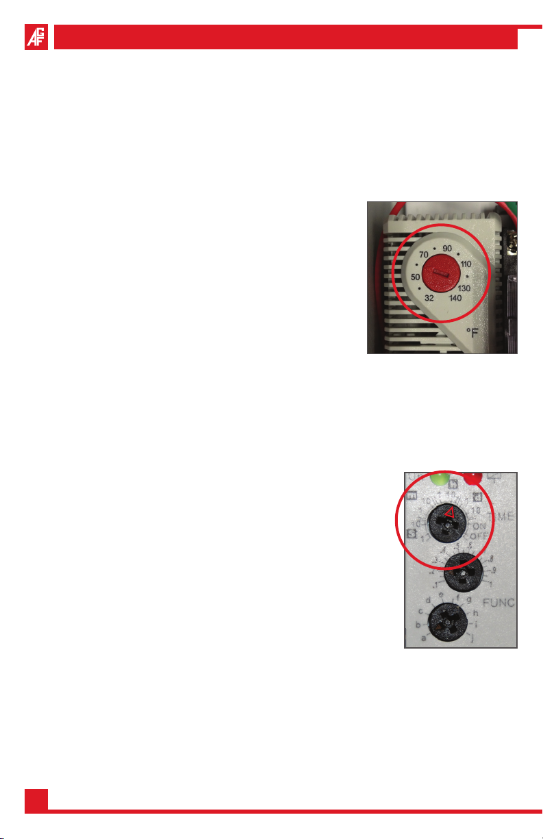
The M5450 features a thermometer on the cabinet door for measuring the ambient
temperature inside the unit. This thermometer is for checking the operating status
of the internal heater. The reading on the thermometer, based on its location in the
cabinet, may range from 40° to 120° F, depending on when in the heater’s cycle
the thermometer is checked.
The system uses a oat-style level switch to monitor the collected condensate.
This Float Switch is tied back to the NEMA 4 Alarm Panel. In the event the Drain
Trap plumbing becomes obstructed and enough condensate accumulates, the
Float Switch will be activated. This will trigger the alarm to sound and the alarm
light to blink. The activation of the alarm and light indicates that the M5450 needs
to be emptied and that there is a possible obstruction in the Drain Trap Y-Strainer
or plumbing that needs to be investigated. A normally open auxiliary contact is
also triggered and is capable of being wired back to a Remote Panel. The Float
Switch is automatically reset when the water level is drained below the switch.
The M5450 is equipped with a “TEST” button to conrm that the Alarm Panel is
functioning properly. When pressed, the “TEST” button causes the local alarm to
sound and the alarm light to blink, and, if utilized, the auxiliary contact to alert the
Remote Panel.
The M5450H is equipped with a Heater Operation Trouble (HOT) Monitor that
veries the performance of the heater. In the event the cabinet door has been
left open or the heater is not keeping up with the temperature demand, the HOT
Monitor will cause the local alarm to sound and the alarm light to blink, and, if
utilized, the auxiliary contact to alert the Remote Panel.
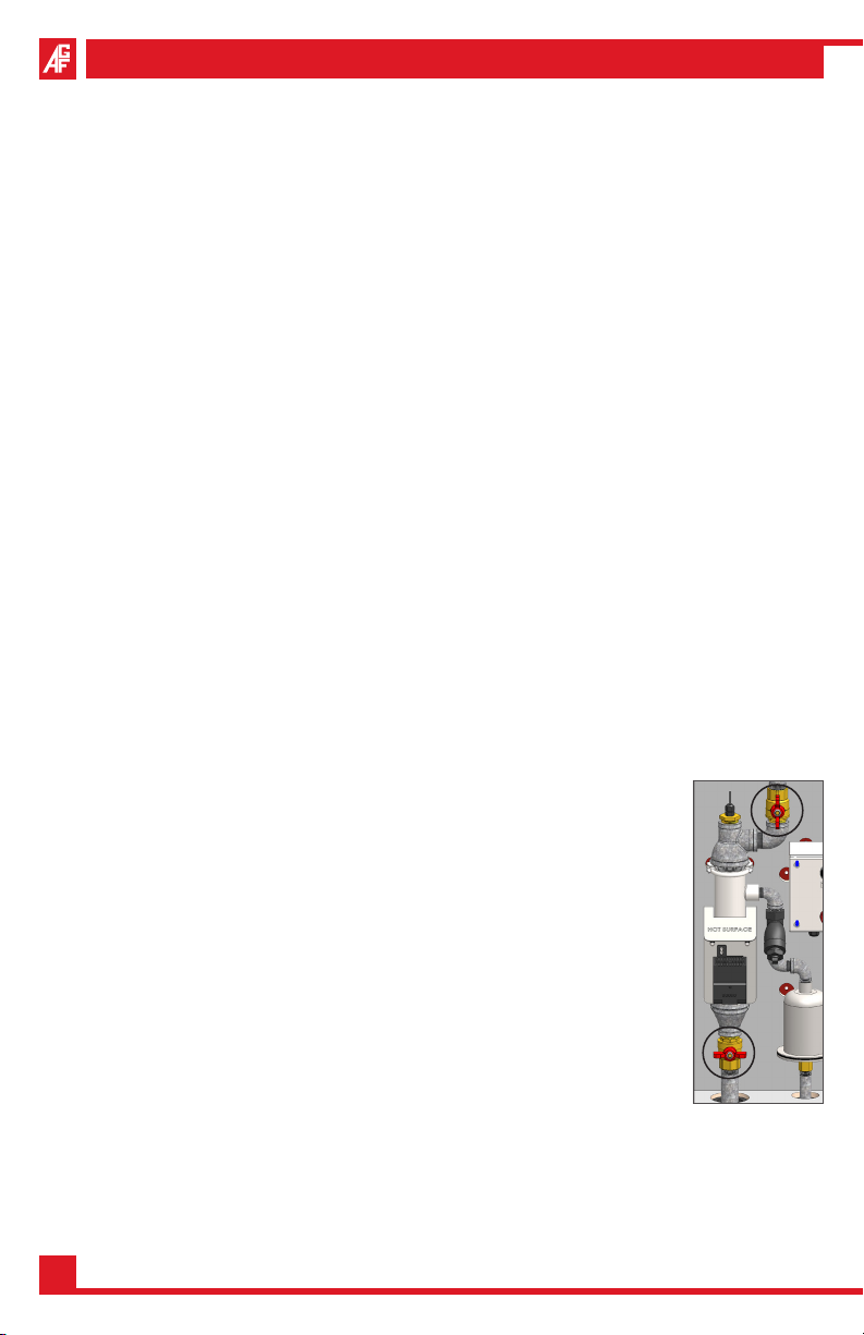
To Collect Condensate per NFPA 25:
1. Open the cabinet door using the supplied keys.
2. Close the Drain Valve (lower valve).
3. Install the 1” Pipe Cap onto the pipe at the bottom of the
cabinet.
4. Open the Supply Valve (upper valve).
5. Close and lock cabinet door using the supplied keys.
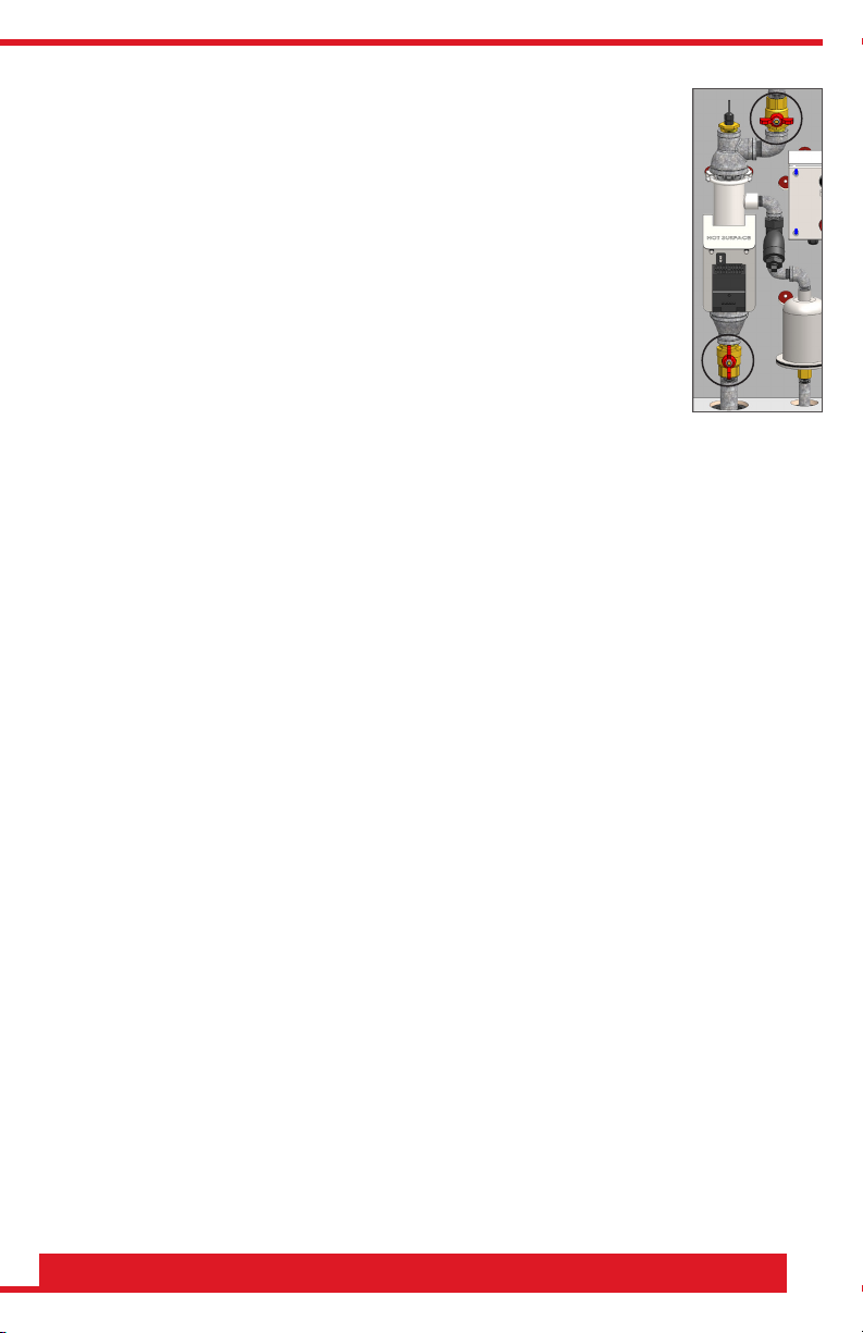
To Drain Condensate per NFPA 25:
NOTE: This procedure will only drain condensate from the main
collection assembly. A small amount of residual water may remain
in the Drain Trap.
1. Open the cabinet door using the supplied keys.
2. Close the Supply Valve (upper valve).
3. Remove the 1” Pipe Cap from the pipe at the bottom of the cabinet.
COLLECT

AGF Manufacturing Inc. • Phone: 610-240-4900 • Fax: 610-240-4906 • www.agfmfg.com 9
NOTE: Hold the pipe secure with a wrench when removing the
Pipe Cap to prevent the pipe or other plumbing from unthreading.
4. Open the Drain Valve (lower valve) and drain the main
collection assembly.
5. Once all the water has been drained, close the Drain Valve.
6. Open the Supply Valve (upper valve) and allow time for any
additional water to accumulate.
7. Repeat the drain process until all the water has been drained.
8. Once all the water has been drained, follow steps 2 through
5 of the “TO COLLECT CONDENSATE” instructions on pg. 8.
MAINTENANCE INSTRUCTIONS
Maintenance is the cornerstone to keeping any system operating correctly and
efciently. It is the building owner’s responsibility to ensure that the M5450 has
been drained, that the heater and alarm are working properly, and that the screen
of the Y-Strainer is clean and free of obstructions. Failure to drain condensate from
the system or conduct regular testing and maintenance could result in system
failure due to freezing. System must be maintained per NFPA 25.
It is especially important that functional testing of the heater and inspection of the
Y-Strainer’s screen be performed before the start of the winter season or when
temperatures begin to approach freezing conditions.
Verify Alarm Operation:
Push and hold the “TEST” button on the Alarm Panel for ve seconds to verify that
the alarm sounds and the alarm light blinks.
Inspect the Y-Strainer Screen:
1. Drain condensate from the main collection assembly following steps 1 through
4 in the “TO DRAIN CONDENSATE” section.
IMPORTANT: DO NOT reopen the supply valve until further instructed.
2. Remove the hex cap from the Y-Strainer body using a wrench. A second
wrench may be needed to prevent the Y-Strainer from turning.
NOTE: Have a small cup ready to capture any residual water that may drain from
the Y-Strainer hex cap.
3. Remove the screen from the body of the Y-Strainer. Inspect and clean, as
necessary.
4. Reinstall the screen and tighten the hex cap.
5. Close the Drain Valve and install the 1” Pipe Cap on the pipe at the bottom
of the cabinet.
DRAIN

Model 5450 COLLECTanDRAIN®Owner’s Manual
10
6. Open the Supply Valve and check for any leaks.
7. Close and lock the cabinet using the supplied keys.
M5450
Verify Heater Operation:
CAUTION: Always take the necessary precautions when entering the Alarm Panel
when 120V power is present.
1. Loosen the four screws on the front of the Alarm
Panel and carefully remove the cover.
2. Take note of the current thermostat set-point.
Thermostat Set-Point____________________
3. Turn the Thermostat clockwise until the heater
turns on.
4. Reset the Thermostat to the previous set-point.
5. Install the Alarm Panel cover and tighten the screws.
M5450H
Verify Heater and Hot Monitor Operation:
CAUTION: Always take the necessary precautions when entering the Alarm Panel
when 120V power is present.
1. Loosen the four screws on the front of the Alarm Panel
and carefully remove the cover.
2. Take note of the current thermostat set-point.
Thermostat Set-Point____________________
3. Take note of the current Time Band (top dial) NOTE:
The leg of the cross with the arrow points to the band.
Time Band_____________________________
4. Turn the top dial to the 10s band.
5. Turn the Thermostat clockwise until the heater turns on.
NOTE: The alarm will sound a few seconds after the heater
turns on.
6. Reset the Thermostat to the previous set-point.
7. Reset the Time Band (top dial) to its previous setting NOTE: The leg of the
cross with the arrow points to the band.
8. Install the Alarm Panel cover and tighten the screws.

AGF Manufacturing Inc. • Phone: 610-240-4900 • Fax: 610-240-4906 • www.agfmfg.com 11
Change Timer Setting (M5450H ONLY):
NOTE: It is the owner’s responsibility to set the timer based upon the climate
conditions of the installed location. The default setting of 2 hours is adequate for
outside temperatures down to 0° F.
1. Disconnect power to the M5450.
2. Loosen the four screws on the Alarm Panel and carefully remove the cover.
3. Turn the middle dial to the desired number of hours, the leg of the cross with
the arrow (highlighted in red) indicates the setting.
IMPORTANT: Unless you are testing the system changing
the top dial Time Band from 10h is not recommended. The
bottom dial should NEVER be changed from the “a” setting.
4. Take note of the new Timer set-point
Timer Set-Point__________________
5. Install the Alarm Panel cover and tighten the four screws.
6. Restore power to the M5450H.
7. Verify power by pressing and holding the “TEST” button.
Change Thermostat Setting:
NOTE: It is the owner’s responsibility to set the thermostat based upon the climate
conditions of the installed location. The default setting of 60° F (the dot between
50 & 70) is adequate for outside temperatures down to 0° F. If operating below
this temperature the set-point should be increased. Consult AGF for set-point
guidelines.
1. Disconnect power to the M5450
2. Loosen the four screws on the Alarm Panel and
carefully remove the cover.
3. Turn the Thermostat clockwise or counterclockwise
to the desired setting.
4. Take note of the new thermostat set-point.
Thermostat Set-Point__________________
5. Install the Alarm Panel cover and tighten the four
screws.
6. Restore power to the M5450H.
7. Verify power by pressing and holding the “TEST” button.

AGF Manufacturing Inc.
100 Quaker Lane • Malvern, PA 19355
Phone: 610-240-4900
Fax: 610-240-4906
www.agfmfg.com
Table of contents
Other AGF Industrial Equipment manuals
Popular Industrial Equipment manuals by other brands

Siemens
Siemens Flender FLUDEX 4600 Series operating instructions

IAI
IAI ELECYLINDER EC-S13 instruction manual

Dreve
Dreve EyeVoIution MAX operating instructions

Pentair
Pentair PENTEK PPC7 Series installation manual

SMC Networks
SMC Networks CKZ5N Series Operation manual

Rockwell Automation
Rockwell Automation VersaView 5100 user manual