TLV QuickTrap FJ32-B User manual

172-65721MA-00 (FJ32-B+BD2) 31 May 2022
Free Float Steam Trap with Bimetal
FJ32-B
QuickTrap®
J32-B
Trap Unit
Copyright © 2022 by TLV CO., LTD.
All rights reserved

172-65721MA-00 (FJ32-B+BD2) 31 May 2022
1
Contents
Introduction ........................................................................ 1
Safety Considerations........................................................ 2
Checking the Piping........................................................... 4
Operation ........................................................................... 5
Specifications..................................................................... 6
Compatibility....................................................................... 6
Configuration...................................................................... 7
Installation.......................................................................... 8
Maintenance..................................................................... 10
Disassembly/Reassembly................................................ 11
Instructions for Plug/Holder Disassembly and Reassembly . 15
Troubleshooting ............................................................... 16
TLV EXPRESS LIMITED WARRANTY............................ 17
Service ............................................................................. 19
Options............................................................................. 20
Introduction
Thank you for purchasing the TLV free float steam trap.
This product has been thoroughly inspected before being shipped from the
factory. When the product is delivered, before doing anything else, check the
specifications and external appearance to make sure nothing is out of the
ordinary. Also be sure to read this manual carefully before use and follow the
instructions to be sure of using the product properly.
This free float steam trap uses a two-bolt flange and three-point seating for a
precision-ground float, increasing heating efficiency and reducing manpower
requirements for maintenance. The two-bolt flange allows the trap to be installed
in either horizontal or vertical piping. This flexibility greatly reduces the time
required for installation, removal, repair and maintenance.
This free float steam trap is suitable for steam mains or branches for
superheated or saturated steam and tracing lines, where extremely small
amounts of condensate are generated, automatically discharging condensate at
slightly lower than saturation temperature. The product is equipped with a built-
in automatic air vent, rapidly discharging large amount of condensate and air at
startup, which reduces start-up time significantly.
If detailed instructions for special order specifications or options not contained in
this manual are required, please contact TLV for full details.
This instruction manual is intended for use with the model(s) listed on the front
cover. It is necessary not only for installation, but for subsequent maintenance,
disassembly/reassembly and troubleshooting. Please keep it in a safe place for
future reference.
172-65721MA-00 (FJ32-B+BD2) 31 May 2022
2
Safety Considerations
Read this section carefully before use and be sure to follow the instructions.
Installation, inspection, maintenance, repairs, disassembly, adjustment and valve
opening/closing should be carried out only by trained maintenance personnel.
The precautions listed in this manual are designed to ensure safety and prevent
equipment damage and personal injury. For situations that may occur as a result of
erroneous handling, three different types of cautionary items are used to indicate
the degree of urgency and the scale of potential damage and danger: DANGER,
WARNING and CAUTION.
The three types of cautionary items above are very important for safety: be sure to
observe all of them as they relate to installation, use, maintenance and repair.
Furthermore, TLV accepts no responsibility for any accidents or damage occurring
as a result of failure to observe these precautions.
Symbols
Indicates a DANGER, WARNING or CAUTION item.
Indicates an urgent situation which poses a threat of death or
serious injury
Indicates that there is a potential threat of death or serious injury
Indicates that there is a possibility of injury or equipment/product
damage
NEVER apply direct heat to the float.
The float may explode due to increased internal pressure, causing
accidents leading to serious injury or damage to property and
equipment.
Install properly and DO NOT use this product outside the
recommended operating pressure, temperature and other
specification ranges.
Improper use may result in such hazards as damage to the product
or malfunctions that may lead to serious accidents. Local
regulations may restrict the use of this product to below the
conditions quoted.
DO NOT use this product in excess of the maximum operating
pressure differential.
Such use could make discharge impossible (blocked).
Take measures to prevent people from coming into direct
contact with product outlets.
Failure to do so may result in burns or other injury from the
discharge of fluids.
Continued on the next page
DANGER
WARNING
CAUTION
WARNING
CAUTION
172-65721MA-00 (FJ32-B+BD2) 31 May 2022
3
When disassembling or removing the product, wait until the
internal pressure equals atmospheric pressure and the
surface of the product has cooled to room temperature.
Disassembling or removing the product when it is hot or under
pressure may lead to discharge of fluids, causing burns, other
injuries or damage.
Be sure to use only the recommended components when
repairing the product, and NEVER attempt to modify the
product in any way.
Failure to observe these precautions may result in damage to the
product and burns or other injury due to malfunction or the
discharge of fluids.
Use only under conditions in which no freeze-up will occur.
Freezing may damage the product, leading to fluid discharge,
which may cause burns or other injury.
Use only under conditions in which no water hammer will
occur.
The impact of water hammer may damage the product, leading
to fluid discharge, which may cause burns or other injury.
Always wear eye protection and heat-resistant gloves when
operating the blowdown valve.
Failure to do so may result in burns or other injury.
When operating the blowdown valve, stand to the side well
clear of the outlet to avoid contact with internal fluids that will
be discharged. Operate the valve slowly and surely, taking
care to avoid the area from which internal fluids are
discharged and any fluids deflected off piping or the ground
etc.
Failure to do so may result in burns or other injury.
Do not tighten the BD2 valve or the BD2 valve seat in excess
of the appropriate tightening torque.
Over-tightening may cause breakage to threaded portions, which
may cause burns, other injuries or damage.
Do not excessively loosen the BD2 valve when opening the
blowdown valve.
The valve stopper pin installed to prevent the BD2 valve from
being removed may break and internal pressure may result in the
BD2 valve being blown off, leading to injuries, damage and fluid
discharge, causing burns.
CAUTION
172-65721MA-00 (FJ32-B+BD2) 31 May 2022
4
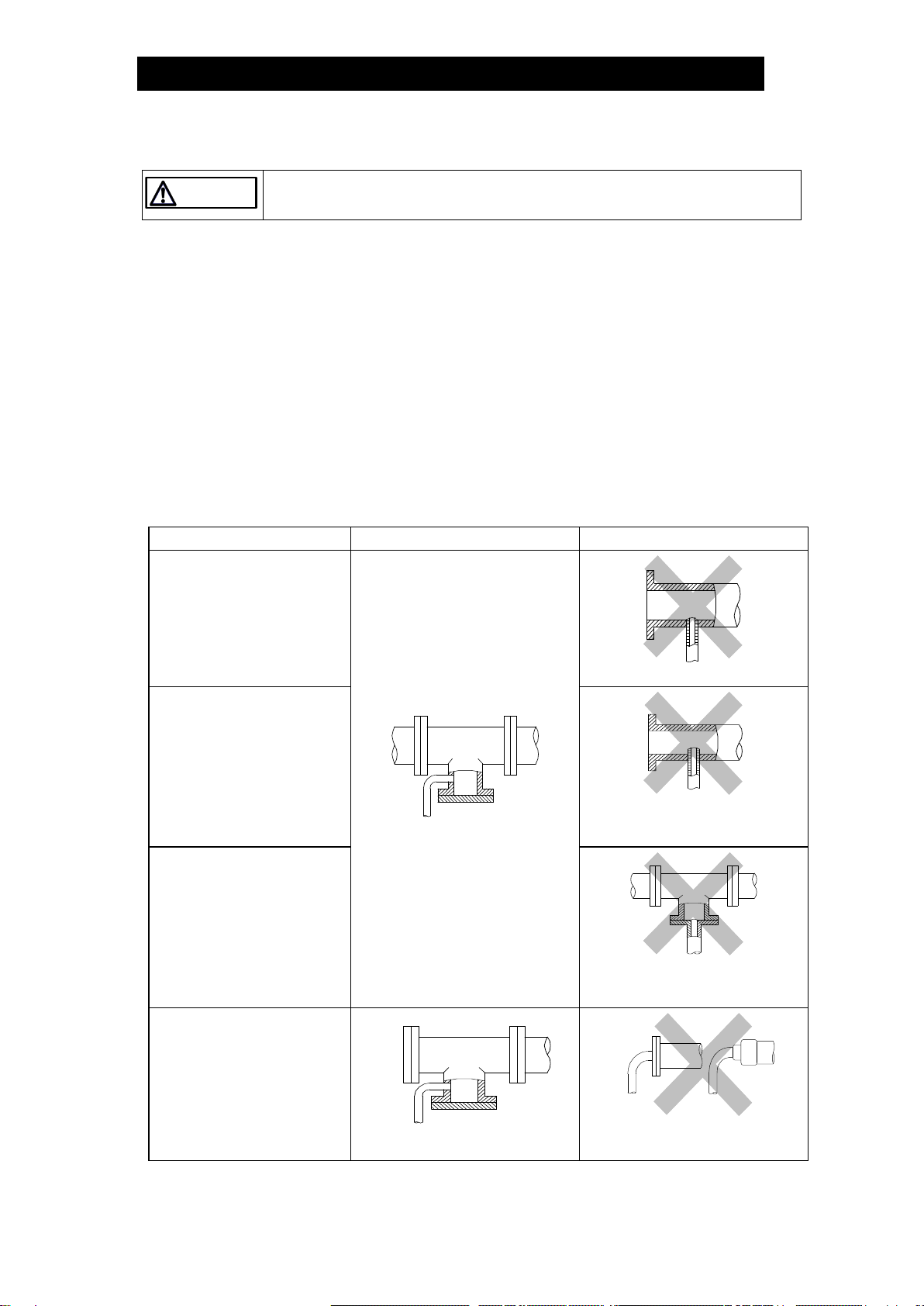
Checking the Piping
Use only under conditions in which no water hammer will occur.
The impact of water hammer may damage the product, leading to fluid discharge,
which may cause burns or other injury.
Check to make sure that the pipes to be connected to the product have been installed
properly.
1. Is the pipe diameter suitable?
2. Is the trap unit installed horizontally?
3. Has sufficient space been secured for maintenance?
4. Have isolation valves been installed at the inlet and outlet? If the outlet is subject to
back pressure, has a check valve (TLV-CK) been installed?
5. Is the inlet pipe as short as possible, with as few bends as possible, and installed
so the liquid will flow naturally down into the product?
6. Has the piping work been done correctly, as shown in the figures below?
7. Using the appropriate tools, have the screws been tightened enough?
Requirement
Correct
Incorrect
Install catchpot with the
proper diameter.
Diameter is too small.
Make sure the flow of
condensate is not
obstructed.
Diameter is too small and inlet
protrudes into pipe interior.
To prevent rust and scale
from flowing into the trap,
the inlet pipe should be
connected 25 to 50 mm (1
to 2 in) above the base of
the T-pipe.
Rust and scale flow into the
trap with the condensate.
When installing on the
blind end, make sure the
flow of condensate is not
obstructed.
Condensate collects in the
pipe.
CAUTION

172-65721MA-00 (FJ32-B+BD2) 31 May 2022
5
Operation
Principles of air and condensate discharge:
1.
Air and Cold Condensate Discharge at
Startup
At startup, before steam is supplied, the
system is cold and the bimetal plate is
flexed downward, keeping the air vent
valve (A) open. This allows for the rapid
discharge of air through vent (A) and cold
condensate through orifice (B) when
steam is first supplied to the system.
2.
Condensate Discharge
After the discharge of initial air and cold
condensate, the heat of the inflowing
steam and condensate cause the bimetal
plate to flex upward, closing the air vent
valve (A). The rising condensate level
causes the float to rise due to buoyancy,
opening the orifice (B) and allowing
condensate to be discharged.
The flexed bimetal keeps the valve closed
while in normal operation.
3.
Discharge of Large Quantities of
Condensate
Increases in the condensate inflow rate
cause the condensate level in the trap to
rise. The float consequently rises and
enlarges the opening of the orifice (B),
allowing more condensate to be
discharged. In this manner, continuous
condensate discharge occurs while the
opening size of the orifice varies
depending on the condensate flow rate.
4.
Closed Position
When the condensate flow rate
decreases, the float falls as condensate is
discharged, closing off the orifice (B). A
water seal is maintained at all times over
the orifice (B) to prevent steam loss.
Air
Steam
Condensate
172-65721MA-00 (FJ32-B+BD2) 31 May 2022
6
Specifications
Install properly and DO NOT use this product outside the recommended
operating pressure, temperature and other specification ranges.
Improper use may result in such hazards as damage to the product or malfunctions
that may lead to serious accidents. Local regulations may restrict the use of this
product to below the conditions quoted.
DO NOT use this product in excess of the maximum operating pressure
differential. Such use could make discharge impossible (blocked).
Use only under conditions in which no freeze-up will occur.
Freezing may damage the product, leading to fluid discharge, which may cause burns
or other injury.
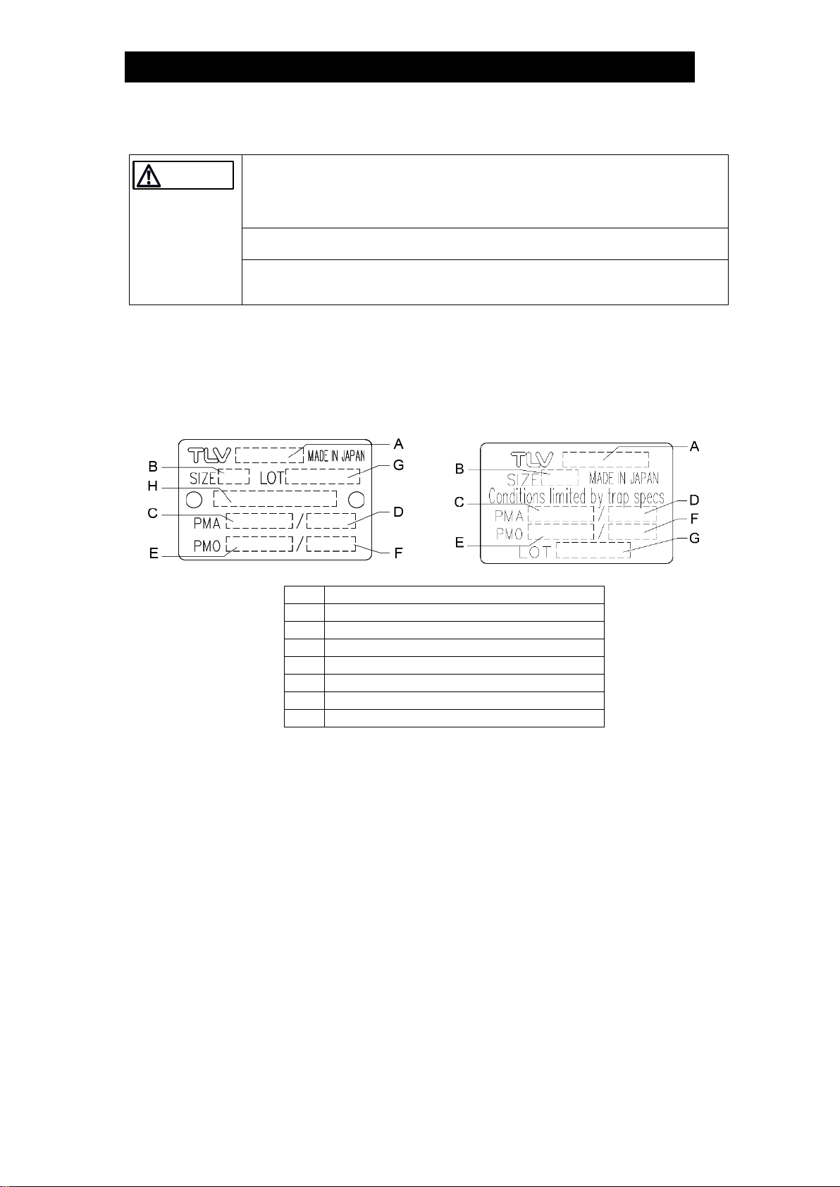
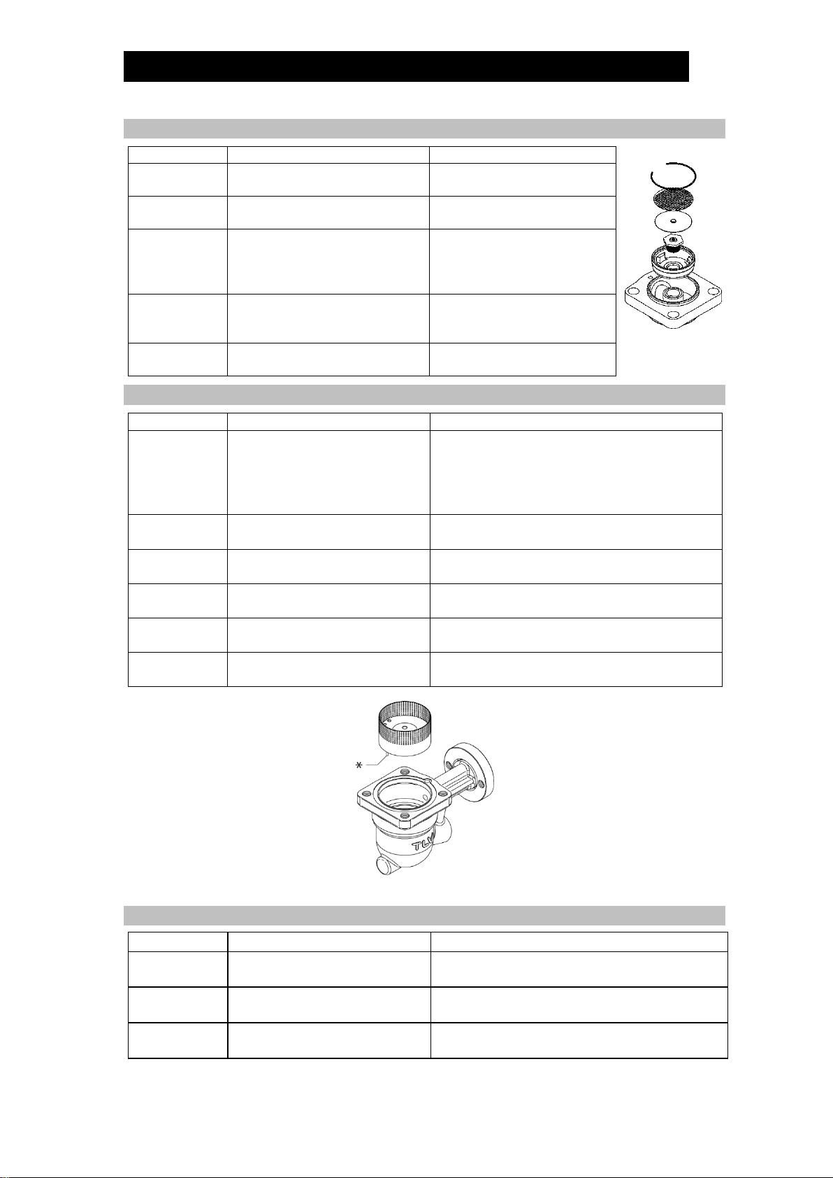
Refer to the product nameplate for detailed specifications.
The specifications displayed on each nameplate apply only to the unit on which it is
mounted. When a trap unit is installed on a connector unit and the PMA/TMA and/or
PMO/TMO values displayed on the two nameplates differ, the specifications for the
assembled products are restricted to the lower values.
Trap Unit
Connector Unit (mounted only on F46)
A
Model
B
Nominal Diameter
C
Maximum Allowable Pressure (PMA)*
D
Maximum Allowable Temperature (TMA)*
E
Maximum Differential Pressure (PMX)
F
Maximum Operating Temperature (TMO)
G
Production Lot No.
H
Valve No.**
*Maximum allowable pressure (PMA) and maximum allowable temperature (TMA) are
PRESSURE SHELL DESIGN CONDITIONS, NOT OPERATING CONDITIONS.
**Valve No. is displayed for products with options. This item is omitted from the nameplate when
there are no options.
Compatibility
The FJ32-B QuickTrap employs connector unit F46 and is not compatible with
QuickTrap models using connector unit F46J. The J32-B trap unit is compatible with
trap stations (V1/V2/V1P/V2P Series) and Quick Station QS10, and can also be
installed on connector unit F32.
The unit name is embossed on the connector body.
CAUTION
172-65721MA-00 (FJ32-B+BD2) 31 May 2022
7
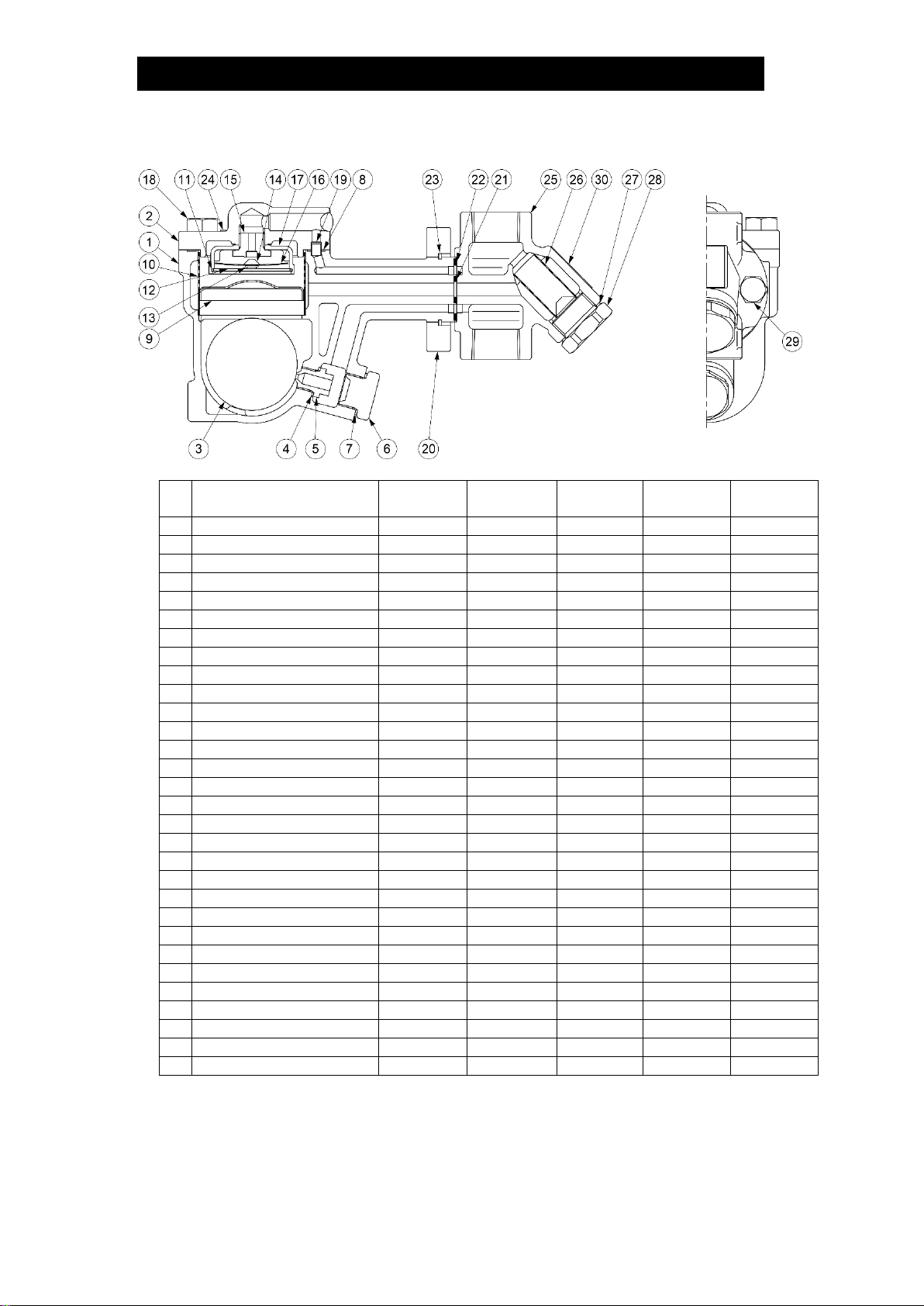
Configuration
No
Part Name
Trap Unit*
Connector
Unit**
Maintenance
Kit
Repair Kit
Float
1
Trap Body
2
Cover
3
Float
4
Orifice Gasket
5
Orifice
6
Orifice Plug
7
Orifice Plug Gasket
8
Cover Gasket
9
Float Cover
10
Screen
11
Spring Clip
12
Screen
13
Spring Clip
14
Air Vent Valve Plug
15
Air Vent Valve Seat
16
Bimetal
17
Bimetal Case
18
Cover Bolt
19
Connector
20
Connector Flange
21
Inner Connector Gasket
22
Outer Connector Gasket
23
Connector Ring
24
Nameplate
25
Connector Body
26
Screen
27
Screen Holder Gasket
28
Screen Holder
29
Connector Bolt
30
Nameplate
*J32-B
**F46

172-65721MA-00 (FJ32-B+BD2) 31 May 2022
8
Installation
Install properly and DO NOT use this product outside the recommended
operating pressure, temperature and other specification ranges.
Improper use may result in such hazards as damage to the product or malfunctions
that may lead to serious accidents. Local regulations may restrict the use of this
product to below the conditions quoted.
Take measures to prevent people from coming into direct contact with product
outlets.
Failure to do so may result in burns or other injury from the discharge of fluids.
Installation, inspection, maintenance, repairs, disassembly and adjustment and valve
opening/closing should be carried out only by trained maintenance personnel.
1. Before installation, be sure to remove all protective seals.
2. Before installing the product, blow out the inlet piping to remove any piping scraps,
dirt and oil. Close the inlet valve after blowdown.
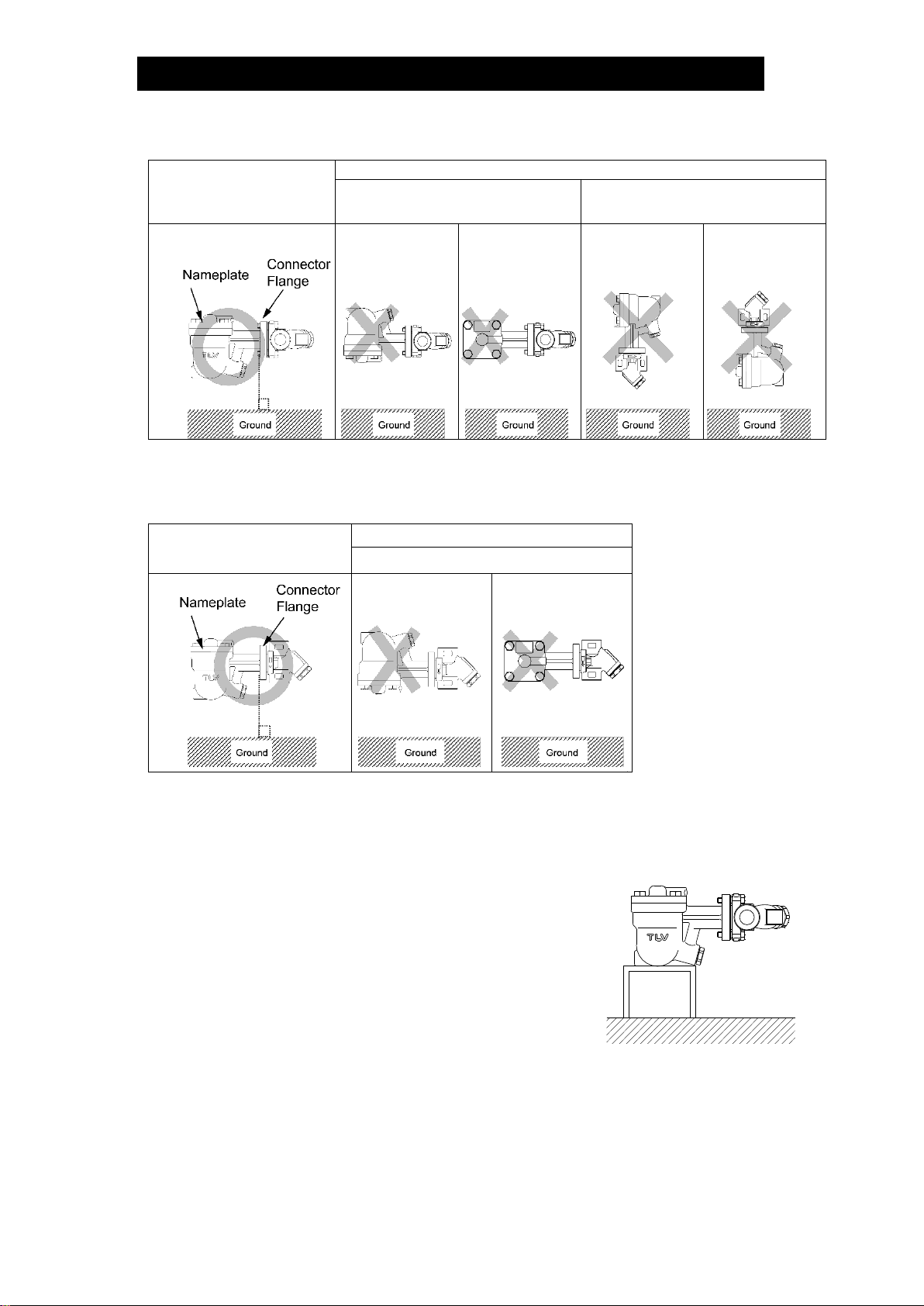
3. Install the connector body so that the arrow is pointing in the direction of flow.
4. The connector body has no restrictions on installation orientation except for the
following conditions: the flange face (for connecting to the trap unit) must be in the
vertical plane, and the trap unit must be installed with the nameplate facing upwards.
5. The trap unit must be inclined no more than 5º horizontally and front-to-back.
6. Install a condensate outlet valve and outlet piping.
7. Open the inlet and outlet valves and ensure that the product functions properly.
If there is a problem, determine the cause using the “Troubleshooting” section in this
manual.
Tolerance Angle for Installation: 5°
Install with the arrow on the connector body pointing in the direction of
flow, with the flange (for connecting to the trap unit) in the vertical plane
and the trap unit with the nameplate facing upwards.
CAUTION
172-65721MA-00 (FJ32-B+BD2) 31 May 2022
9
Installation Examples: Horizontal Piping
Correct
Incorrect
Nameplate is not facing
upwards
Connector Flange is not in the
vertical plane
Note: If the product is installed incorrectly, it may not be possible to obtain the specified
performance. There is also a risk of serious accidents on the outlet (secondary) side. The
examples shown here are only a selection, and are exclusively for explanation purposes.
Installation Examples: Vertical Piping
Correct
Incorrect
Nameplate is not facing upwards.
Note: If the product is installed incorrectly, it may not be possible to obtain the specified
performance. There is also a risk of serious accidents on the outlet (secondary) side. The
examples shown here are only a selection, and are exclusively for explanation purposes.
Note for Screwed Connection:
When products with screwed connections are installed on
horizontal piping, there is a danger that the weight of the
trap unit will cause the connector body to rotate on the
pipe, putting the trap mechanism out of the horizontal
plane. To prevent this, tighten the screws securely. In
cases where the product is affected by vibrations or by
external contact, it is recommended that the trap unit
should be supported to prevent rotation (sample support
shown to the right).
172-65721MA-00 (FJ32-B+BD2) 31 May 2022
10
Maintenance
Take measures to prevent people from coming into direct contact with product
outlets.
Failure to do so may result in burns or other injury from the discharge of fluids.
Be sure to use only the recommended components when repairing the
product, and NEVER attempt to modify the product in any way.
Failure to observe these precautions may result in damage to the product and
burns or other injury due to malfunction or the discharge of fluids.
Operational Check
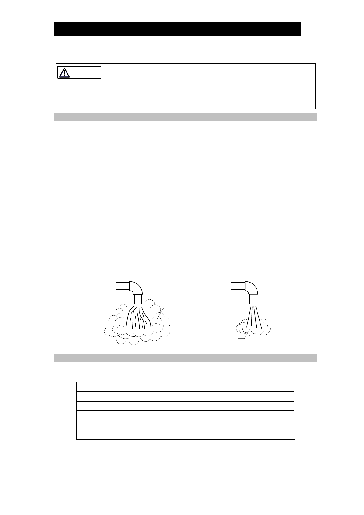
A visual inspection of the following items should be done on a daily basis to determine
whether the product is operating properly or has failed. Periodically (at least biannually)
the operation should also be checked by using diagnostic equipment such as a
stethoscope, thermometer, TLV Pocket TrapMan or TrapMan.
If the product should fail, it may cause damage to piping and equipment, resulting in
faulty or low quality products or losses due to steam leakage.
Normal:
Condensate is discharged continuously, together with flash steam,
and the sound of flow can be heard. If there is very little
condensate, there is almost no sound of flow.
Blocked:
(Discharge Impossible)
No condensate is discharged. The product is quiet and makes no
noise, and the surface temperature of the product is low.
Blowing:
Live steam continually flows from the outlet and there is a
continuous metallic sound.
Steam Leakage:
Live steam is discharged through the product outlet together with
condensate, accompanied by a high-pitched sound.
(When conducting a visual inspection, flash steam is sometimes mistaken for steam leakage.
For this reason, the use of a steam trap diagnostic instrument - such as TLV TrapMan - in
conjunction with the visual inspection is highly recommended.)
Flash Steam
Live Steam Leakage
Parts Inspection
When parts have been removed, or during periodic inspections, use the following table
to inspect the parts and replace any that are found to be defective.
Procedure
Gaskets:
Check for warping or scratches
Screens:
Check for clogging or corrosion
Air Vent (Bimetal):
Check for scratches
Air Vent Valve Seat:
Check for scratches
Float:
Check for scratches or dents
Body Interior:
Check for build-up
Orifice Opening:
Check for dirt, oil film wear or scratches
CAUTION
White jet containing
water droplets
Clear, slightly bluish jet

172-65721MA-00 (FJ32-B+BD2) 31 May 2022
11
Disassembly/Reassembly
NEVER apply direct heat to the float.
The float may explode due to increased internal pressure, causing accidents leading
to serious injury or damage to property and equipment.
When disassembling or removing the product, wait until the internal pressure
equals atmospheric pressure and the surface of the product has cooled to
room temperature.
Disassembling or removing the product when it is hot or under pressure may lead
to discharge of fluids, causing burns, other injuries or damage.
Use the following procedures to remove components. Use the same procedures in
reverse to reassemble.
(Installation, inspection, maintenance, repairs, disassembly, adjustment and valve
opening/closing should be carried out only by trained maintenance personnel.)
Detaching/Reattaching the Trap Unit and Connector Body
Part
During Disassembly
During Reassembly
Connector
Bolts 26
Remove with a socket wrench
Consult the table of tightening torques and
tighten to the proper torque
Trap Unit 1
Remove the trap unit
Follow the special instructions below
(see fig. A)
Connector
Gaskets 21,22
Remove with a scraper without
scratching the seating surface
of the trap body.
Make sure there are no pieces of the old
gasket left on the sealing surfaces of the body
and then reattach; Be careful not to drop the
new gasket
Attaching the Trap Unit to the Connector Body (Figure A)
1. If attaching a new trap unit, be sure to remove the
protective cap from the connector flange. Be careful not to
drop the gaskets when removing the cap.
2. Grasp the end of the trap unit and align its gasket housing
with the indentation on the connector body.
3. Once aligned, insert and finger tighten the connector bolts.
Verify that the trap unit is within the allowable inclination.
Figure A
Detaching/Reattaching the Cover
Part
During Disassembly
During Reassembly
Cover Bolt 18
Remove with a socket wrench
Consult the table of tightening torques and
tighten to the proper torque
Cover 2
Remove by lifting up and off
Make sure there are no pieces of the old
gasket on the sealing surfaces, align the
cover with the body and connector and
reattach
Connector 19
Remove the connector
Reinsert it into hole in body
Cover Gasket
8
Remove the gasket and clean
sealing surfaces
Replace with a new gasket
WARNING
CAUTION
172-65721MA-00 (FJ32-B+BD2) 31 May 2022
12
Disassembly/Reassembly of Components Inside the Cover
Part
During Disassembly
During Reassembly
Spring Clip 11
Pinch the insides together and
remove from the cover
Insert it securely into the
groove
Screen 12
Remove, being careful not to
misshape
Replace, being careful not to
misshape
Bimetal 16/
Air Vent Valve
14,15 /
Spring Clip 13
Remove air vent parts from
cover
Make sure to reinsert in the
proper orientation (Fig. B)
Air Vent Valve
Seat 15
Remove with a socket wrench
Consult the table of
tightening torques and
tighten to the proper torque
Bimetal Case
17
Remove from the cover
Place it in the cover
Disassembly/Reassembly of Components Inside the Trap Body
Part
During Disassembly
During Reassembly
Float Cover
& Screen 9,10
Lift straight up and out while
rocking slowly
Align the arrows on the float cover/screen and
the body, insert with the tab on the bottom
fitting into the slot in the body; make sure the
screen does not stick out out of the body
(Figure C)
Float 3
Remove, being careful not to
scratch the polished surface
Insert, being careful not to scratch the
polished surface
Orifice Plug 6
Remove with a socket wrench
Consult the table of tightening torques and
tighten to the proper torque
Orifice Plug
Gasket 7
Remove the gasket and clean
sealing surfaces
Replace with a new gasket; coat surfaces with
anti-seize
Orifice 5
Remove with a socket wrench
Consult the table of tightening torques and
tighten to the proper torque
Orifice Gasket
4
Remove the gasket and clean
sealing surfaces
Replace with a new gasket; coat surfaces with
anti-seize
* Tab
Disassembly/Reassembly of Components Inside the Connector Body
Part
During Disassembly
During Reassembly
Screen Holder
25
Remove with a socket wrench
Consult the table of tightening torques and
tighten to the proper torque
Screen Holder
Gasket 24
Remove the gasket and clean
sealing surfaces
Replace with a new gasket; coat surfaces with
anti-seize
Screen 20
Remove with a needle-nose
pliers
Insert securely into the connector body
Figure B
Figure C

172-65721MA-00 (FJ32-B+BD2) 31 May 2022
13
Table of Tightening Torques
Part Name
Torque
Distance Across Flats
Nm
(lbf·ft)
mm
(in)
Orifice 5
30
(22)
10
(3/8)
Orifice Plug 6
80
(59)
24
(15/16)
Air Vent Valve Seat 15
30
(22)
17
(21/32)
Cover Bolt 18
50
(37)
16
(5/8)
Screen Holder 25
150
(110)
38
(11/2)
Bolt 26
(Trap Body 1/Connector Body 22)
39
(28)
14
(9/16)
NOTE:
-Coat all threaded portions with anti-seize.
-If drawings or other special documentation were supplied for the
product, any torque given there takes precedence over values
shown here.
(1 Nm 10 kgcm)
172-65721MA-00 (FJ32-B+BD2) 31 May 2022
14
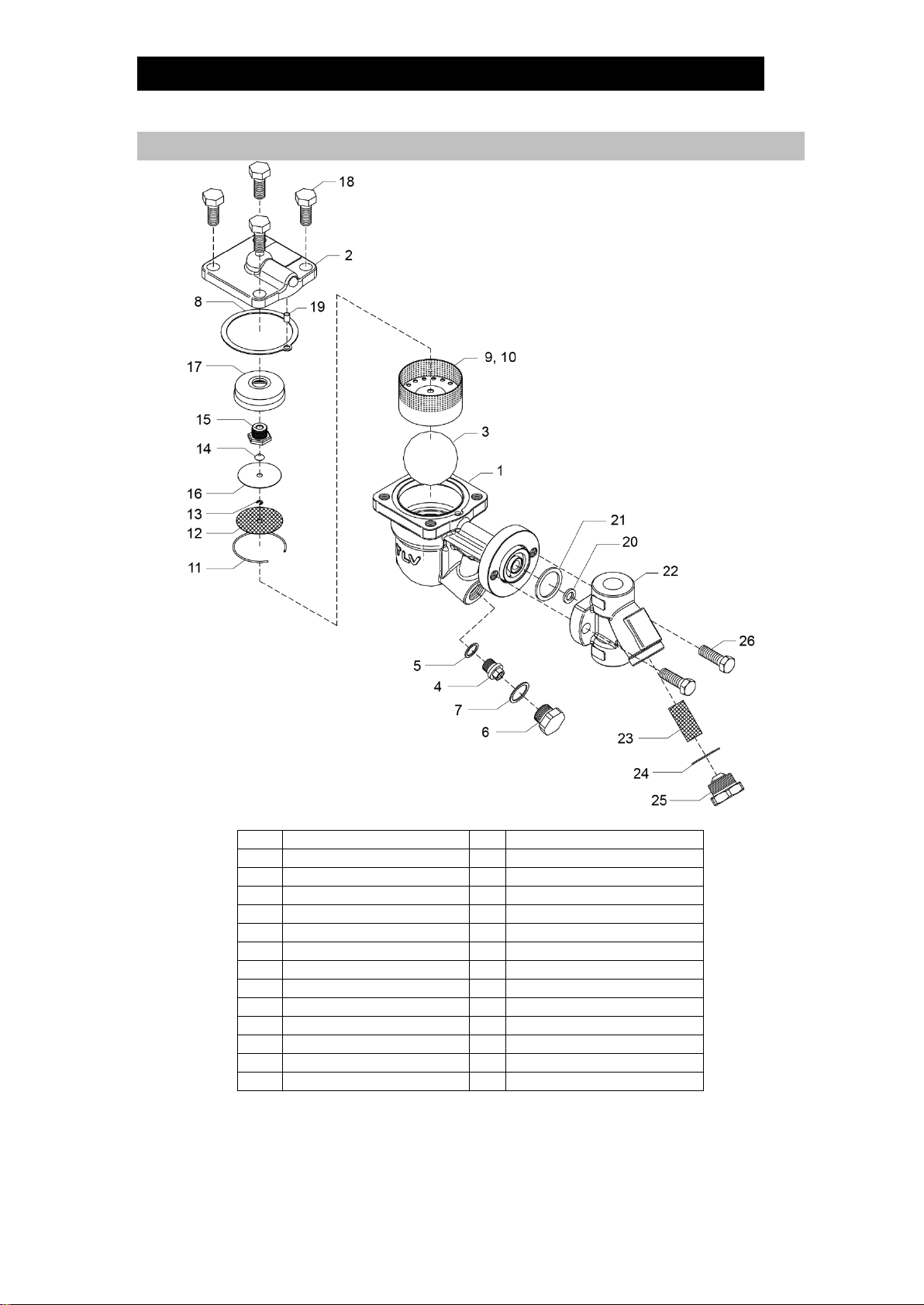
Exploded View
No
Name
No
Name
1
Trap Body
14
Air Vent Valve Plug
2
Cover
15
Air Vent Valve Seat
3
Float
16
Bimetal
4
Orifice
17
Bimetal Case
5
Orifice Gasket
18
Cover Bolt
6
Orifice Plug
19
Connector
7
Orifice Plug Gasket
20
Inner Connector Gasket
8
Cover Gasket
21
Outer Connector Gasket
9
Float Cover
22
Connector Body
10
Screen
23
Screen
11
Spring Clip
24
Screen Holder Gasket
12
Screen
25
Screen Holder
13
Spring Clip
26
Connector Bolt
No. 1 –21, 26: Trap Unit
No. 22 –25: Connector Unit

172-65721MA-00 (FJ32-B+BD2) 31 May 2022
15
Instructions for Plug/Holder Disassemblyand Reassembly
The seal on the threaded plugs/holders found on TLV products is formed by a flat metal
gasket. There are various installation orientations for the gaskets, such as horizontal,
diagonal and downward, and the gasket may be pinched in the thread recesses during
assembly.
Instructions for Disassembly and Reassembly
1. Remove the plug/holder using a tool of the specified size (distance across flats).
2. The gasket should not be reused. Be sure to replace it with a new gasket.
3. Clean the gasket surfaces of the plug/holder and the product body using a rag and/or
cleaning agents, then check to make sure the surfaces are not scratched or
deformed.
4. Coat both the gasket surface of the plug/holder and the threads of the plug/holder
with anti-seize, then press the gasket onto the center of the gasket surface of the
plug/holder, making sure the anti-seize affixes the gasket tightly to the plug/holder.
Check to make sure the gasket is not caught in the recesses of the threads.
5. Hold the plug/holder upside down to make sure that the anti-seize makes the gasket
stick to the plug/holder even when the plug/holder is held upside down.
6. Screw the plug/holder by hand into the product body while making sure that the
gasket remains tightly affixed to the center of the gasket surface of the plug/holder.
Make sure the entire gasket is making contact with the gasket surface of the product
body. It is important at this point to make sure the gasket is not pinched in the
thread recesses of the plug/holder.
7. Tighten the plug/holder to the proper torque.
8. Next, begin the supply of steam and check to make sure there is no leakage from
the part just tightened. If there is leakage, immediately close the inlet valve and, if
there is a bypass valve, take the necessary steps to release any residual pressure.
After the surface of the product cools to room temperature, repeat the procedure
beginning from step 1.
172-65721MA-00 (FJ32-B+BD2) 31 May 2022
16
Troubleshooting
When disassembling or removing the product, wait until the internal pressure
equals atmospheric pressure and the surface of the product has cooled to
room temperature.
Disassembling or removing the product when it is hot or under pressure may lead
to discharge of fluids, causing burns, other injuries or damage.
If the product fails to operate properly, use the following table to locate the cause and
remedy.
Problem
Cause
Remedy
No condensate is
discharged
(blocked) or
discharge is poor
The float is damaged or filled with
condensate
Replace with a new float
The orifice opening, screen or piping are
clogged with rust and scale
Clean parts
The bimetal is scratched or damaged
Replace with a new bimetal
The product operating pressure exceeds
the maximum specified pressure or there
is insufficient pressure differential
between the product inlet and outlet
Compare specifications and
actual operating conditions
Steam locking has occurred
Perform a bypass blowdown or
close the trap inlet valve and
allow the trap to cool
Steam is
discharged or
leaks from the
outlet
(blowing)
(steam leakage)
Build-up on the seating surface of the
orifice or rust and scale build-up beneath
the float
Clean parts
Scratches on the orifice
Replace with a new orifice
The float is misshapen or has surface
build-up
Clean or replace with a new
float
Improper installation orientation
Correct the installation
The bimetal air vent valve surface and/or
the air vent valve seat are scratched or
have surface build-up
Clean or replace with a new
bimetal/air vent valve seat
The bimetal is damaged
Replace with a new bimetal
Trap vibration
Lengthen the inlet piping and
fasten it securely
Steam is leaking
from a place other
than the outlet
Gasket deterioration or damage
Replace with a new gasket
Improper tightening torques were used
Tighten to the proper torque
Float frequently
becomes damaged
Water hammer has occurred
Study and correct the piping
NOTE: When replacing parts with new, use the parts list for reference, and replace with parts
from the maintenance kit, repair kit, etc. Please note that replacement parts are only
available as part of a replacement parts kit.
CAUTION

172-65721MA-00 (FJ32-B+BD2) 31 May 2022
17
TLV EXPRESS LIMITED WARRANTY
Subject to the limitations set forth below, TLV CO., LTD., a Japanese corporation
(“TLV”), warrants that products which are sold by it, TLV International Inc. (“TII”) or one
of its group companies excluding TLV Corporation (a corporation of the United States of
America), (hereinafter the “Products”) are designed and manufactured by TLV,
conform to the specifications published by TLV for the corresponding part numbers (the
“Specifications”) and are free from defective workmanship and materials. The party
from whom the Products were purchased shall be known hereinafter as the “Seller”.
With regard to products or components manufactured by unrelated third parties (the
“Components”), TLV provides no warranty other than the warranty from the third party
manufacturer(s), if any.
Exceptions to Warranty
This warranty does not cover defects or failures caused by:
1. improper shipping, installation, use, handling, etc., by persons other than TLV, TII
or TLV group company personnel, or service representatives authorized by TLV; or
2. dirt, scale or rust, etc.; or
3. improper disassembly and reassembly, or inadequate inspection and maintenance
by persons other than TLV or TLV group company personnel, or service
representatives authorized by TLV; or
4. disasters or forces of nature or Acts of God; or
5. abuse, abnormal use, accidents or any other cause beyond the control of TLV, TII
or TLV group companies; or
6. improper storage, maintenance or repair; or
7. operation of the Products not in accordance with instructions issued with the
Products or with accepted industry practices; or
8. use for a purpose or in a manner for which the Products were not intended; or
9. use of the Products in a manner inconsistent with the Specifications; or
10. use of the Products with Hazardous Fluids (fluids other than steam, air, water,
nitrogen, carbon dioxide and inert gases (helium, neon, argon, krypton, xenon and
radon)); or
11. failure to follow the instructions contained in the TLV Instruction Manual for the
Product.
Duration of Warranty
This warranty is effective for a period of one (1) year after delivery of Products to the
first end user. Notwithstanding the foregoing, asserting a claim under this warranty must
be brought within three (3) years after the date of delivery to the initial buyer if not sold
initially to the first end user.
ANY IMPLIED WARRANTIES NOT NEGATED HEREBY WHICH MAY ARISE BY OPERATION
OF LAW, INCLUDING THE IMPLIED WARRANTIES OF MERCHANTABILITY AND FITNESS
FOR A PARTICULAR PURPOSE AND ANY EXPRESS WARRANTIES NOT NEGATED
HEREBY, ARE GIVEN SOLELY TO THE INITIAL BUYER AND ARE LIMITED IN DURATION
TO ONE (1) YEAR FROM THE DATE OF SHIPMENT BY THE SELLER.
Exclusive Remedy
THE EXCLUSIVE REMEDY UNDER THIS WARRANTY, UNDER ANY EXPRESS WARRANTY
OR UNDER ANY IMPLIED WARRANTIES NOT NEGATED HEREBY (INCLUDING THE IMPLIED
WARRANTIES OF MERCHANTABILITY AND FITNESS FOR A PARTICULAR PURPOSE), IS
REPLACEMENT; PROVIDED: (a) THE CLAIMED DEFECT IS REPORTED TO THE SELLER IN
WRITING WITHIN THE WARRANTY PERIOD, INCLUDING A DETAILED WRITTEN

172-65721MA-00 (FJ32-B+BD2) 31 May 2022
18
DESCRIPTION OF THE CLAIMED DEFECT AND HOW ANDWHEN THE CLAIMED
DEFECTIVE PRODUCT WAS USED; AND (b) THE CLAIMED DEFECTIVE PRODUCT AND A
COPY OF THE PURCHASE INVOICE IS RETURNED TO THE SELLER, FREIGHT AND
TRANSPORTATION COSTS PREPAID, UNDER A RETURN MATERIAL AUTHORIZATION AND
TRACKING NUMBER ISSUED BY THE SELLER. ALL LABOR COSTS, SHIPPING COSTS, AND
TRANSPORTATION COSTS ASSOCIATED WITH THE RETURN OR REPLACEMENT OF THE
CLAIMED DEFECTIVE PRODUCT ARE SOLELY THE RESPONSIBILITY OF BUYER OR THE
FIRST END USER. THE SELLER RESERVES THE RIGHT TO INSPECT ON THE FIRST END
USER’S SITE ANY PRODUCTS CLAIMED TO BE DEFECTIVE BEFORE ISSUING A RETURN
MATERIAL AUTHORIZATION. SHOULD SUCH INSPECTION REVEAL, IN THE SELLER’S
REASONABLE DISCRETION, THAT THE CLAIMED DEFECT IS NOT COVERED BY THIS
WARRANTY, THE PARTY ASSERTING THIS WARRANTY SHALL PAY THE SELLER FOR THE
TIME AND EXPENSES RELATED TO SUCH ON-SITE INSPECTION.
Exclusion of Consequential and Incidental Damages
IT IS SPECIFICALLY ACKNOWLEDGED THAT THIS WARRANTY, ANY OTHER EXPRESS
WARRANTY NOT NEGATED HEREBY, AND ANY IMPLIED WARRANTY NOT NEGATED
HEREBY, INCLUDING THE IMPLIED WARRANTIES OF MERCHANTABILITY AND FITNESS
FOR A PARTICULAR PURPOSE, DO NOT COVER, AND NEITHER TLV, TII NOR ITS TLV
GROUP COMPANIES WILL IN ANY EVENT BE LIABLE FOR, INCIDENTAL OR
CONSEQUENTIAL DAMAGES, INCLUDING, BUT NOT LIMITED TO LOST PROFITS, THE
COST OF DISASSEMBLY AND SHIPMENT OF THE DEFECTIVE PRODUCT, INJURY TO
OTHER PROPERTY, DAMAGE TO BUYER’S OR THE FIRST END USER’S PRODUCT,
DAMAGE TO BUYER’S OR THE FIRST END USER’S PROCESSES, LOSS OF USE, OR
OTHER COMMERCIAL LOSSES. WHERE, DUE TO OPERATION OF LAW, CONSEQUENTIAL
AND INCIDENTAL DAMAGES UNDER THIS WARRANTY, UNDER ANY OTHER EXPRESS
WARRANTY NOT NEGATED HEREBY OR UNDER ANY IMPLIED WARRANTY NOT NEGATED
HEREBY (INCLUDING THE IMPLIED WARRANTIES OF MERCHANTABILITY AND FITNESS
FOR A PARTICULAR PURPOSE) CANNOT BE EXCLUDED, SUCH DAMAGES ARE
EXPRESSLY LIMITED IN AMOUNT TO THE PURCHASE PRICE OF THE DEFECTIVE
PRODUCT. THIS EXCLUSION OF CONSEQUENTIAL AND INCIDENTAL DAMAGES, AND THE
PROVISION OF THIS WARRANTY LIMITING REMEDIES HEREUNDER TO REPLACEMENT,
ARE INDEPENDENT PROVISIONS, AND ANY DETERMINATION THAT THE LIMITATION OF
REMEDIES FAILS OF ITS ESSENTIAL PURPOSE OR ANY OTHER DETERMINATION THAT
EITHER OF THE ABOVE REMEDIES IS UNENFORCEABLE, SHALL NOT BE CONSTRUED TO
MAKE THE OTHER PROVISIONS UNENFORCEABLE.
Exclusion of Other Warranties
THIS WARRANTY IS IN LIEU OF ALL OTHER WARRANTIES, EXPRESS OR IMPLIED, AND
ALL OTHER WARRANTIES, INCLUDING BUT NOT LIMITED TO THE IMPLIED WARRANTIES
OF MERCHANTABILITY AND FITNESS FOR A PARTICULAR PURPOSE, ARE EXPRESSLY
DISCLAIMED.
Severability
Any provision of this warranty which is invalid, prohibited or unenforceable in any
jurisdiction shall, as to such jurisdiction, be ineffective to the extent of such invalidity,
prohibition or unenforceability without invalidating the remaining provisions hereof, and
any such invalidity, prohibition or unenforceability in any such jurisdiction shall not
invalidate or render unenforceable such provision in any other jurisdiction.

172-65721MA-00 (FJ32-B+BD2) 31 May 2022
19
Service
For Service or Technical Assistance: Contact your TLV representative or your regional
TLV office.
In Europe:
Daimler-Benz-Straße 16-18, 74915 Waibstadt, Germany
Tel:
Fax:
[49]-(0)7263-9150-0
[49]-(0)7263-9150-50
Units 7 & 8, Furlong Business Park, Bishops Cleeve,
Gloucestershire GL52 8TW, U.K.
Tel:
Fax:
[44]-(0)1242-227223
[44]-(0)1242-223077
Parc d’Ariane 2, bât. C, 290 rue Ferdinand Perrier, 69800 Saint Priest,
France
Tel:
Fax:
[33]-(0)4-72482222
[33]-(0)4-72482220
In North America:
13901 South Lakes Drive, Charlotte, NC 28273-6790, U.S.A.
Tel:
Fax:
[1]-704-597-9070
[1]-704-583-1610
In Mexico and Latin America:
Av. Jesús del Monte 39-B-1001, Col. Hda. de las Palmas, Huixquilucan,
Edo. de México, 52763, Mexico
Tel:
Fax:
[52]-55-5359-7949
[52]-55-5359-7585
In Oceania:
Unit 8, 137-145 Rooks Road, Nunawading, Victoria 3131, Australia
Tel:
Fax:
[61]-(0)3-9873 5610
[61]-(0)3-9873 5010
In East Asia:
36 Kaki Bukit Place, #02-01/02, Singapore 416214
Tel:
Fax:
[65]-6747 4600
[65]-6742 0345
5/F, Building 7, No.103 Caobao Road, Xuhui District, Shanghai, China
200233
Tel:
Fax:
[86]-(0)21-6482-8622
[86]-(0)21-6482-8623
No.16, Jalan MJ14, Taman Industri Meranti Jaya, 47120 Puchong,
Selangor, Malaysia
Tel:
Fax:
[60]-3-8052-2928
[60]-3-8051-0899
252/94 (K-L) 17th Floor, Muang Thai-Phatra Complex Tower B,
Rachadaphisek Road, Huaykwang, Bangkok 10310, Thailand
Tel:
Fax:
[66]-2-693-3799
[66]-2-693-3979
#302-1 Bundang Technopark B, 723 Pangyo-ro, Bundang, Seongnam,
Gyeonggi, 13511, Korea
Tel:
Fax:
[82]-(0)31-726-2105
[82]-(0)31-726-2195
In the Middle East:
Building 2W, No. M002, PO Box 371684, Dubai Airport Free Zone,
Dubai, UAE
Email:
In Other Countries:
881 Nagasuna, Noguchi, Kakogawa, Hyogo 675-8511, Japan
Tel:
Fax:
[81]-(0)79-427-1818
[81]-(0)79-425-1167
Manufacturer:
881 Nagasuna, Noguchi, Kakogawa, Hyogo 675-8511, Japan
Tel:
Fax:
[81]-(0)79-427-1800
[81]-(0)79-422-2277
Table of contents
Other TLV Industrial Equipment manuals


