TREVIL 5040 EASYFORM Programming manual

50xx Easyform-ed0811
¥
5040 EASYFORM
5050 EASYFORM AC 7.5kW
5055 EASYFORM AC 15kW
Usage and Maintenance

50xx Easyform-ed0811

50xx Easyform-ed0811 ¥
50xx EASYFORM 3Index
Index
1. Introduction 5
1.1. Content and purpose of this manual 5
1.2. Safety precautions 5
1.3. Manufacturer’s liability 5
2. Description of the machine 6
2.1. How to identify the machine 6
2.2. Technical data 6
3. Installation 7
3.1. Upon receiving the goods 7
3.2. Assembling 7
3.3. Electrical connections 7
3.4. Steam connection (only types without boiler) 7
3.5. Water connection (only types with boiler) 7
3.6. Training of the operator 9
3.7. Compressed air connection (only for models with sleeves tensioning) 9
3.8. Other adjustments 9
4. Operation 10
4.1. Safety precautions 10
4.2. Before starting 10
4.3. Operation 10
4.5. Upon terminating work 10
5. Use of the control board 12
5.1. PROGRAMMING section 12
5.2. PROGRAMMING section - advanced features 12
5.3. MANUAL CONTROLS section 12
5.4. Pressing cycle counter meters 12
6. Maintenance 13
6.1. Maintenance allowed to the user 13
6.2. Maintenance to be carried out by the technician every six months 14
7. Troubleshooting 16
7.1. Solution to common problems, allowed to the user 16
7.2. Solution to failures, for the use of the authorised service center 17
8. Prolonged stop, Transportation or Decommissioning 19
8.1. Prolonged stop 19
8.2. Transportation 19
8.3. Decommissioning 19
9. Technical diagrams 20
10. Spare parts diagrams 29

50xx Easyform-ed0811
50xx Easyform-ed0811 ¥
50xx EASYFORM 5
1. Introduction
1.1. Content and purpose of this manual
This manual contains instructions concerning the installation and
maintenance of pressing equipment in conformity to the present
European Community Directive. Therefore you will find information
on the following subjects:
• Information on machine technical features;
• Instructions on installation and operating of the machine.
• Instructions on maintenance and servicing.
• Technical diagrams
• Exploded views of spare parts
This manual is for installer’s and technician’s use; they will have to
read and understand it carefully before installing, using or servicing
the machine.
This manual should be kept with the machine and read before
operation; in case of loss or damage please ask the builder for a
new copy.
The builder is not responsible for any consequences arising from the
neglecting of all instructions reported in this manual.
The content of this manual is property of the manufacturer. Duplication
of this manual is forbidden.
1.2. Safety precautions
Ignoring the following safety precautions can cause damage either to
people, linen, animals and to the machine.
The following symbols, on the machine and in this manual, advise
about possible risks.
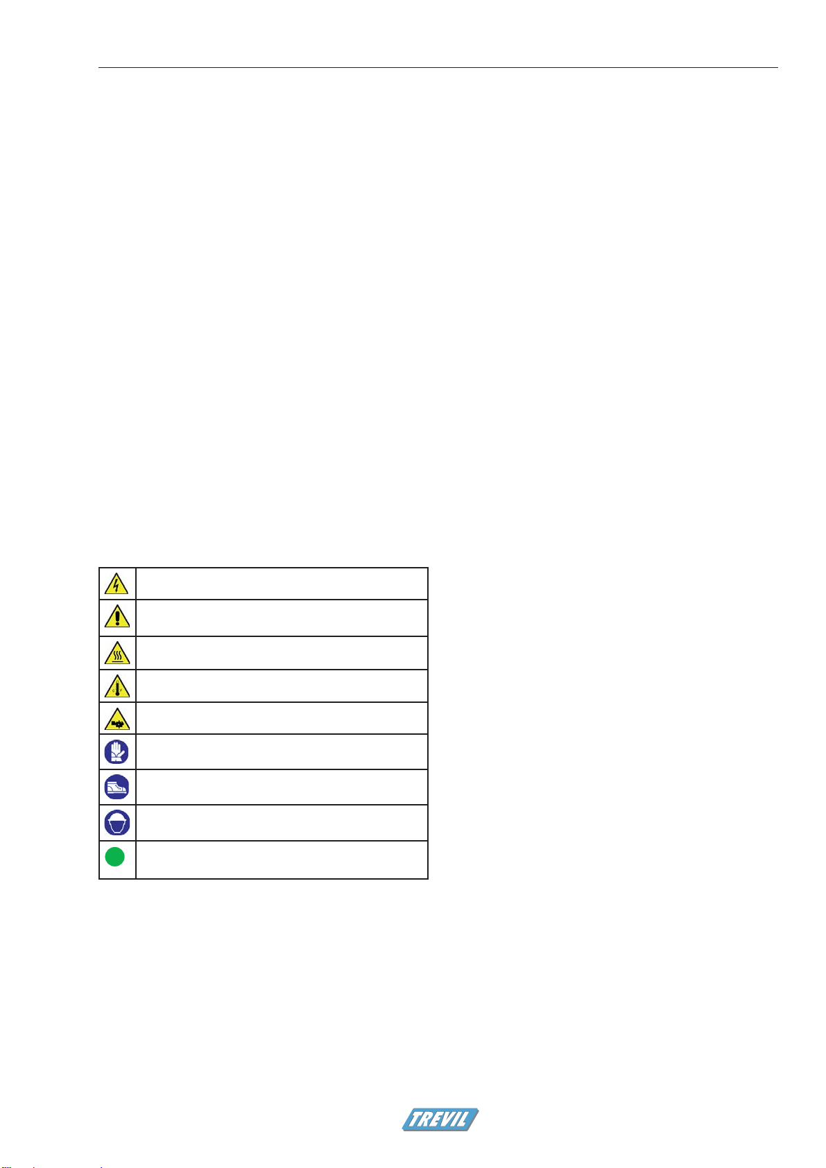
Legend of the safety symbols found on the machine and in this
book:
Warning: live electricity
General warning: follow instructions to avoid damage to
the machine or to people.
Warning: hot surface / burn hazard
Warning: high temperature
Risk of injury to hands of feet
Wear gloves
Wear protective shoes
Wear a helmet
i
Information, notice, advice
Carefully read the entire manual before installing, operating or
servicing the machine.
Installation and maintenance the product described in this manual
must be performed by authorised and qualified technicians who
know the products and are acquainted with standards for installation
of industrial pressing equipment.
The builder is not responsible for external connections not duly
performed.
The product described in this manual must be used only to iron
garments and linen. Any other use is forbidden unless builder
authorizes it in writing.
Do not press fabrics contaminated by dangerous substances such
as explosives, inflammable, etc. Make sure they are rinsed or aired
before ironing.
To prevent fire hazard or explosions do not stand near the machine
with explosive or inflammable products.
Use of the machine is allowed only to professional operators who
have been trained on how to operate the machine. In any case the
use of the machine is forbidden to children under 14 years of age.
Do not remove safety protection devices.
Do not leave machine unattended while in operation.
Do not remove safety symbols from the machine
1.3. Manufacturer’s liability
This manual instructions are not intended to substitute, but only to
combine obligations of current legislation on safety standards.
With reference to information included in this manual, the
manufacturer is not responsible in case of:
• neglect of local safety standards during machine utilisation;
• incorrect installation of the machine;
• neglect or incorrect observance of instructions included in this
manual;
• conection to electric plant having voltage and frequency that
differ from those specified in the technical data tag;
• connection to electric plant non compliant with EC safety
requirement, in particular if the plant lacks grounding, thermal
magnetic protection and differential protection;
• unauthorized changes on the machine;
• utilisation of the machine by unauthorized, untrained or non-
professional operators;
• neglect of maintenance operations;
• use of non original spare parts.
Introduction
50xx Easyform-ed0811
¥
50xx EASYFORM6
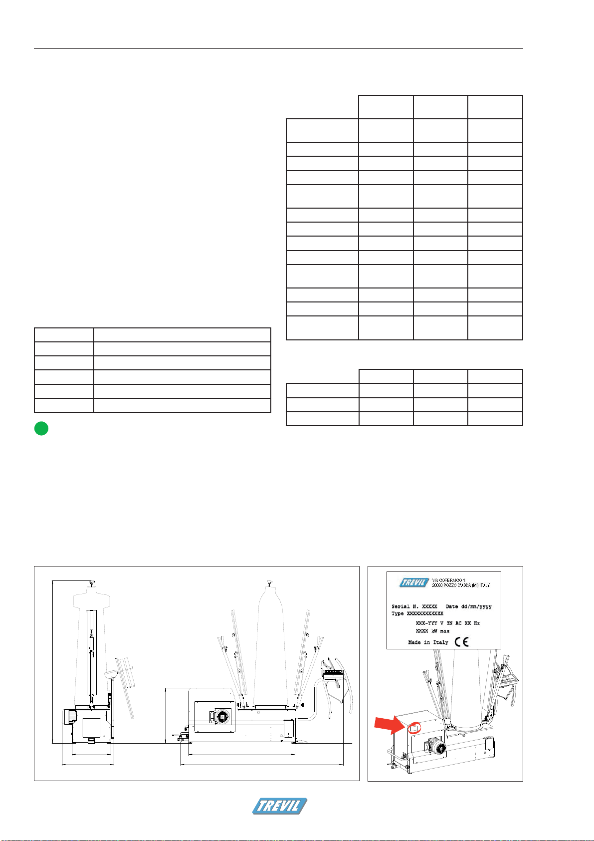
171.5cm (68”)
41cm (16”) 112.5cm (44”)
171.5cm (68”)
58.5cm (23”)
55cm (22”)
Figure 2.1 - Machine dimensions Figure 2.2 - How to identify the machine
2. Description of the
machine
The machine described in this manual is a form finisher for garments
for the upper body.
The form finisher is designed for professional use only in:
• Garment manufacturing industries;
• Large and small Industrial dry cleaners;
• Garment finishing industries.
The form finisher must be utilized only by qualified personnel, who
have been specifically trained on this type of machinery.
The manufacturer does not accept any responsibility for damage
caused to persons or things due to improper, erroneous or
unreasonable utilization of the machine.
2.1. How to identify the machine
The machine is identified by a technical data plate. The plate is found
on the machine cabinet, as shown in picture 2.2. Do not alter or
modify in any way the data on the identification plate. Do not remove
the identification plate.
Description of the data in the identification plate
Serial N 5 digits serial number
Type Product code
V Tension
Hz Frequency (cycles)
kW Power absorption
Date Date of production
i
This manual describes all the versions of the machine. Be-
fore reading the manual identify the version of the ma-
chine you own by reading the machine “type” in the technical
data plate. While reading the manual take into account only
the information related to the version of machine you own.
2.2. Technical data
For machine dimensions see Figure 2.1.
5040
5042
5050
5052
5055
5057
Electrical
requirements 400V 50Hz 400V 50Hz 400V 50Hz
Steam inlet 1/2” -- --
Condensate return 1/2” -- --
Steam pressure 600 kPa -- --
Boiler heating
element -- 7,5 kW 15 kW
Water inlet -- 16 mm 16 mm
Boiler exhaust -- 1/2" 1/2"
Pump -- 0,8 kW 0,8 kW
Blower motor 1,5 kW 1,5 kW 1,5 kW
Steam consump-
tion 15-20 kg/h -- --
Weight 105-120 Kg 125-140 Kg 125-140 Kg
Noise
Ambient tempe-
rature 15 - 40 °C 15 - 40 °C 15 - 40 °C
Only for models with sleeves tensioning:
5042 5052 5057
Air inlet 1/4” 1/4” 1/4”
Air pressure 600-700 kPa 600-700 kPa 600-700 kPa
Air consumption 30 nl/min 30 nl/min 30 nl/min
Description of the machine
50xx Easyform-ed0811 ¥
50xx EASYFORM 7
3. Installation
3.1. Upon receiving the goods
The machine is delivered mounted on crate and protected by a plastic
film and, in some cases, by a carboard box.
1. Position the crated machine near to the final location of
installation. The crated machine must be moved using suitable
devices, such as a forklift (Figure 3.1)
2. Unpack the machine and separate cardboard from plastic.
Dispose of carton and plastic according to local regulations.
3. Unscrew the bolts that fix the machine to the crate
4. Move the machine from the crate to its final position.
CAUTION - To avoid damaging the machine, do not move
the machine by grabbing the form or the clamps.
CAUTION - The machine can be moved by
hand by experienced personnel only. Wear
gloves, helmet and protective shoes when moving the ma-
chine.
3.2. Assembling
3.2.1. Packing list
The package contains:
1. Machine body.
2. Form with clamps, pad and cover
3. Set of two sleeve expanders and two manual vent clamps.
4. Instruction manual.
Upon receiving the goods, check that the pakcage contains all the
above listed items.
3.2.2. Mounting the form in place
Refer to Figure 3.2.
1. Loosen screw (A) found on support (B).
2. Insert the form (C) on the support (B).
3. Tighten screw (A).
4. Fit the pad and cover on the form.
5. If the machine is provided with sleeve arms: insert pin (D) into
the slot to block the rotation of the form.
3.3. Electrical connections
WARNING - The electrical connection is to be made by
a licensed electrician only and according to local safety
regulations.
The manufacturer is not responsible for damage or injury caused by
improper installation.
Refer to Figure 3.3.
1. Install a multi-pole switch (circuit breaker) to facilitate installation
and service operations. See table 3.5 for rating and type of
connection.
2. In most countries the circuit breaker should include a
protection against overcurrents (e.g. thermal-magnetic
circuit breaker or fuse). If using a fuse, see power absorbtion
on the identification plate of the machine (see figure 2.2).
In some countries the circuit breaker must include a ground
fault interrupt protection.
3. If the appliance is not provided with power cord, mount a cord
of suitable length. For the choice of the cord type refer to table
3.5.
4. Mount a plug on the power cord, see table 3.5 for rating.
5. Connect the plug to the circuit breaker. The cable should hang
in a gentle curve.
6. Check that the motor is rotating counterclockwise, otherwise
switch two of the three phases wires.
WARNING -The electrical line must be properly grounded
to insure the safety of the operator.
i
INDICATION - If a Ground Fault Interrupt protection is in-
stalled: every month test the safety of the circuit by press-
ing the Test button of the circuit breaker. The protection ought
to trip. If it does not, call a technician immediately, as the safety
of the equipment is impaired.
Table 3.5 - Data for electric connection
Type Plug Power cord
5040
5042
Plug 3P+N+T 400V 3N 10A as
per standard IEC60309
Type H05VV-F
5 x 1mm2
5050
5052
Plug 3P+N+T 400V 3N 25A as
per standard IEC60309
Type H05VV-F
5 x 2,5mm2
5055
5057
Plug 3P+N+T 400V 3N 32A as
per standard IEC60309
Type H05VV-F
5 x 4mm2
WARNING - The power cord can be replaced only by an
authorised service center.
3.4. Steam connection (only types with-
out boiler)
WARNING - The steam connection is to be made by a li-
censed technician only and according to local safety regu-
lations.
Refer to Figure 3.4.
Connect the machine to a steam source with steam pressure at 5 bar
(75 PSI) capable of providing 20 Kg/h (45 lbs/hr) of steam.
The numbers in the figure indicate the follwoing parts (not supplied
with the machine):
1 – Steam line
2 – Condensate return line
3 – Ball valve
4 – Check valve
5 – Steam trap
WARNING - Do not connect the machine to a steam line
having pressure exceeding recommended valuse. Risk of
serious damage to the machine and injury to people.
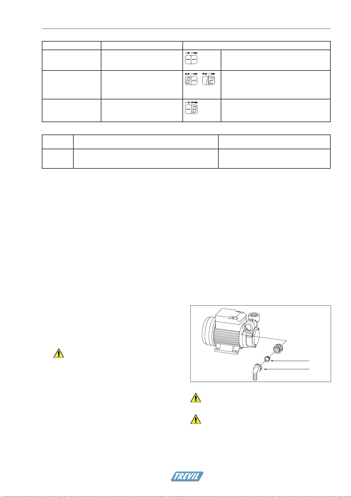
3.5. Water connection (only types with
boiler)
WARNING - The connection is to be made by a licensed
technician only and according to local safety regulations.
Refer to Figure 3.5.
• Connect the water inlet fitting (1) with the water line.
• install a non-return valve* and a faucet or ball valve on
the water mains
• connect the valve to the water inlet nozzle with a 16mm
diameter tube rated for the pressure of the water mains in
your area*.
*For EU countries: these items must be approved according to
standard EN 61770.
WARNING - Use tap water. Do not add softening
products.
• Connect the boiler discharge fitting (2) to the waste water line.
The tube used for the connection must be suitable to carry hot
water and steam.
Installation
> Continued on page 9

50xx Easyform-ed0811
¥
50xx EASYFORM8
5040: min 10A @ 400V 50Hz
5042: min 10A @ 400V 50Hz
5050: min 25A @ 400V 50Hz
5052: min 25A @ 400V 50Hz
7,5 kW
5055: min 32A @ 400V 50Hz
5057: min 32A @ 400V 50Hz
15 kW
1
2
3
5
4
D
A
B
C
Figure 3.1 - How to move the crated machine
Figure 3.3 - Electrical connection
Figure 3.4 - Steam connection
Installation
Only machine without boiler
(models 5040-5042)
Figure 3.2 - Mounting the form
Choose electric components approved as per
standard IEC60309

50xx Easyform-ed0811 ¥
50xx EASYFORM 9
6bar (90PSI)
6bar (90PSI)
1
2
Figure 3.6- Compressed air connectionm (only for models with sleeves tensioning)
WARNING - The connection to the drainage system
must ensure that no leakage of steam or hot water
occurs during the boiler discharge operation
Thermally insulate the discharge pipes.
If necessary, install tanks or devices that allow hot water to cool
before reaching the drainage system.
3.6. Training of the operator
The technician must instruct the operator on how to perform the boil-
er discharge procedure.
The operator must be advised that:
• during the discharge operation, the boiler expels hot water
mixed to steam;
• the discharge operation can be carried out only if the pressure
in the boiler is below 1 bar;
• the connection of the boiler exhaust to the drainage system
must be kept in good order and must be verified every time
before performing the boiler discharge procedure.
3.7. Compressed air connection (only for
models with sleeves tensioning)
WARNING - The steam connection is to be made by a li-
censed technician only and according to local safety regu-
lations.
Refer to Figure 3.6.
1. Connect the machine to a compressed air source with minimum
pressure 6 bar (90 PSI)
2. Make connections as indicated
3. Set the general pressure regulator on the machine at 6 bar (90
PSI)
WARNING - Do not operate the machine with air pressure
exceeding 6 bar. Risk of damage to the machine.
3.8. Other adjustments
The machine is supplied with the control panel folded against the side
of the the machine cabinet.
Rotate the support of the control panel to bring it in the most
comfortable position.
Figure 3.5 - Water connection
Only machine with boiler
(models 5050-5055-5052-5057)
Installation

50xx Easyform-ed0811
¥
50xx EASYFORM10
4. Operation
The machine described in this manual is a form finisher for garments
for the upper body.
The form finisher is designed for professional use only in:
• Garment manufacturing industries;
• Large and small Industrial dry cleaners;
• Garment finishing industries.
The form finisher must be utilized only by qualified personnel, who
have been specifically trained on this type of machinery.
4.1. Safety precautions
During operation the appliance is under electrical ten-
sion:
• Do not operate machinery with partially exposed or frayed
wiring.
• Never permit water to come into contact with machine:
danger of electrical shock, short-circuiting and damage
to machine may result.
• Do not open the machine cabinet.
The appliance has various parts that reach extremely high
temperatures:
• Do not leave the machine unattended while it is on.
• Keep all flammable substances away from machine, to
avoid risk of fire.
• Do not open machine body.
• Do not replace cover and padding while machine is hot
(wait at least 2 hours after turning it off). Always check
the temperature of the form before proceeding to substi-
tute covers.
The appliance generates hot steam vapors - Stay clear of
steam reflex jet.
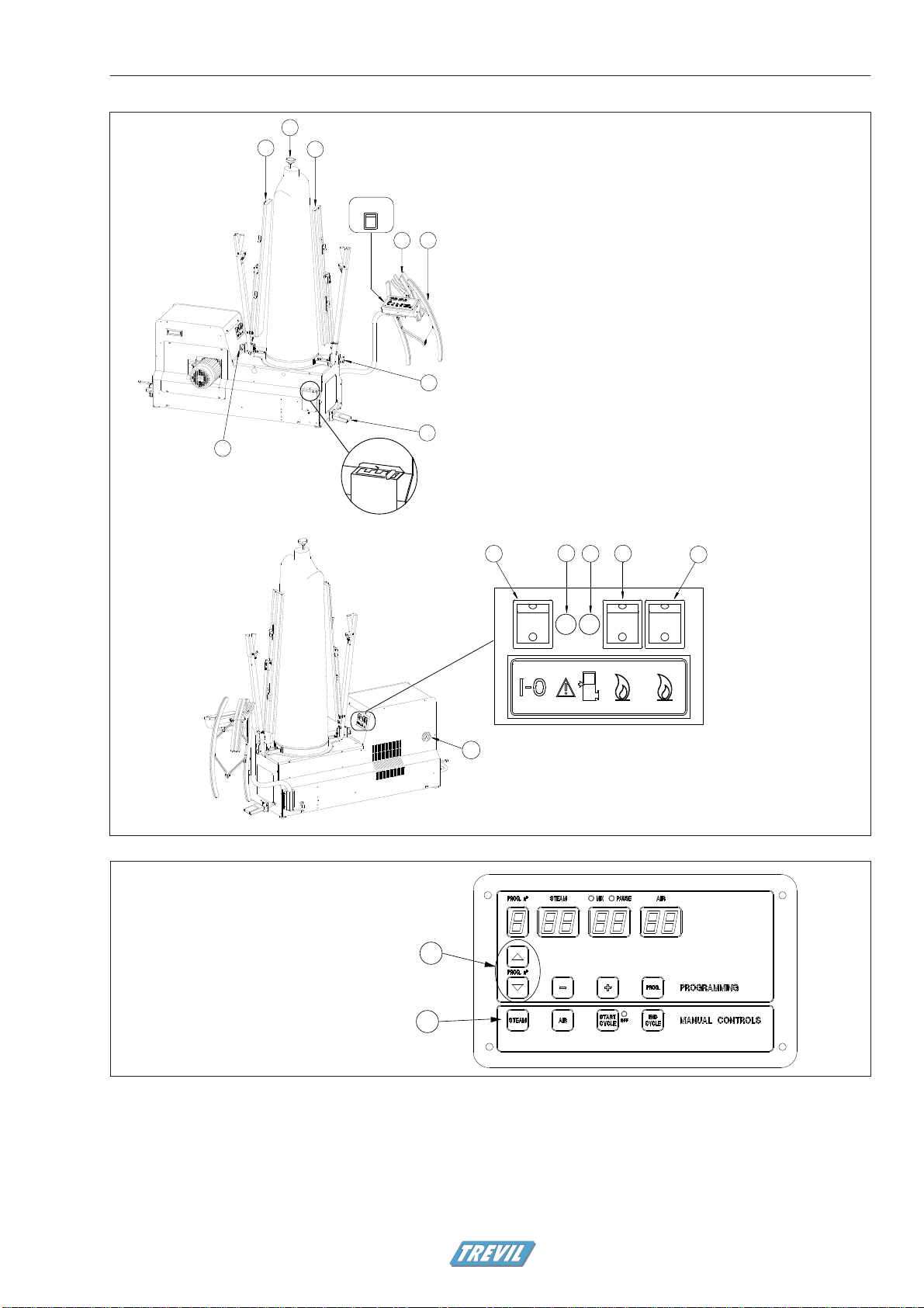
4.2. Before starting
Refer to figure 4.1
4.2.1. Model without boiler
1. Open the steam and condensate return valves.
2. Turn on the main power switch (1).
4.2.2. Model with boiler
1. Open the water feed valve.
2. Check that the boiler discharge valve is closed.
3. Turn on the main power switch (1).
4. Turn on the boiler switch (11).
5. Turn on the heating element switch (12).
6. Only for model 5055: turn on the second heating element (13).
This heating element may be kept off for energy saving if the
machine is to be used for few garments a day. If you realize that
the boiler needs too long to build up pressure, then you can
turn on the auxiliary heating element at any time.
4.3. Operation
Refer to figures 4.1 and 4.2
4.3.1. Settings
1. Adjust the pressure of the front and rear clamps so that they
hold the garment in place during the finishing cycle:
• turn knob (4) clockwise to reduce the pressure;
• turn knob (4) anticlockwise to increase the pressure.
2. Adjust the blowing strength according to the garment: move
lever (5) towards + or - to increase or decrease blowing
strength.
4.3.2 Pressing
1. Use buttons (A) on the control panel to choose the cycle most
suitable to the garment to be finished.
2. Position the garment on the form and adjust shoulder width by
means of knob (9).
3. If needed, change the shape of the bag using the strings.
4. Close the front and rear clamps (8 and 7).
5. Insert sleeve expanders (3) and close any vents with manual
vent clamps (2).
6. Step on the START pedal (6) to start the finishing cycle.
WARNING - The general warning light (14) indicates that
one of the safety protections has tripped. Should it turn on
during usage, turn off the appliance immediately and report to
a service center.
4.5. Upon terminating work
4.5.1. Model without boiler
1. Turn off the power switch (1) and the switch installed on the
mains.
2. Close steam and condensate return valves.
4.5.2. Model with boiler
1. Turn off the power switch (1) and the boiler switches (11-12-
13).
2. Turn off the switch installed on the mains.
3. Close the water feed valve.
Operation
50xx Easyform-ed0811 ¥
50xx EASYFORM 11
"
#
798
23
1
4
6
5
4
13
12
11 14
10
15
Figure 4.2 - Control panel
(A) Program selection buttons
(B) Manual controls section
Operation
Figure 4.1 - Parts of the machine
All models:
(1) ON/OFF switch
(2) Two vent clamps
(3) Two sleeve expanders
(4) Clamps pressure adjustment knob
(5) Blowing strength adjustment lever
(6) START pedal
(7) Rear clamp
(8) Front clamp
(9) Shoulder width adjustment knob
Only models with boiler
(10) Pressure gauge boiler
(11) Main boiler switch
(12) Heating element switch
(13) Second heating element switch
(14) General warning light
(15) Water level lamp

50xx Easyform-ed0811
¥
50xx EASYFORM12 Use of the control board
5. Use of the control
board
The microprocessor programmer manages the pressing cycle in all of
its functions. The programmer can store up to 10 programs.
The control panel is subdivided into 2 sections:
• PROGRAMMING: allows storage of 10 different work pro-
grams
• MANUAL CONTROLS: allows manual function of main press-
ing functions.
When the machine is switched on the control panel shows the last
program used.
5.1. PROGRAMMING section
5.1.1. Pressing times
The programming section consists of :
• Program number display: from 0 to 9
• STEAM time display: from 00 to 99 seconds
• MIX / PAUSE time display. The two-figure display is shared by
the two functions MIX (mixed steam + air) and PAUSE (pause
between steam and blowing; used e.g. for touch ups)
• AIR time display: blowing time
• 5 programming buttons, as described in the following.
To program a pressing cycle, do as follows:
1. Press the button PROG ( ) on the panel. The STEAM display
and the PROG display begin to flash.
2. Press buttons
or to increase or reduce the steam time.
3. Press the PROG. button ( ) to memorize the steam time.
4. The green light MIX and the display below begin to flash: press
or to set a time of mixed steam + air after steaming, if
needed.
5. Press the PROG. button to memorize the mix time. If you have
memorized a MIX time, go to point 8.
6. If MIX time is zero, the green light PAUSE and the display below
begin to flash: press or to set a pause time between steam
and blowing, if needed (e.g. for touch ups with the iron)
7. Press the PROG. button to memorize the pause time.
8. The AIR indicator starts to flash. Press or to set blowing
time.
9. Press the PROG. button. The display stops to flash. Programming
is finished
If you need to change only one of the times, repeat all steps without
modifying the other times.
Mix and Pause times can be used or not, depending on the needs.
Table 5.1 shows the possible combinations.
5.2. PROGRAMMING section - advanced
features
The PROGRAMMING sections allows adjustment of several param-
eters. Figure 5.3 shows the look of the displays during programming
of advanced parameters.
The status of each function remains stored in the memory associated
to the program in which it was entered.
1. To access advanced programming press and hold the PROG.
button until the letter H appears in the program number dis-
play
2. The STEAM display shows the number of the parameter being
programmed. Please refer to Table 5.2 for description of the
parameters and their status;
3. The AIR display shows a flashing number indicating the param-
eter value. Press or to change parameter value
4. Press PROG. to memorize the value and step forward to the
next function;
5. Press PROG. several times, until the displays return to normal
pressing times visualization.
The settings of the advanced parameters remain stored in the memo-
ry associated to the program in which they were entered.
For example: if the machine is running program number 5 and the
user excludes the photocell, the photocell will remain excluded for
future use of program number 5, even after switching off the ma-
chine.
5.3. MANUAL CONTROLS section
STEAM: Keep pressed to manually steam the garment.
AIR: Press once to start blowing. Press it again to stop blowing. In
order to have manual MIX press STEAM during the blowing
operation.
START CYCLE: Starts the pressing cycle.
END CYCLE: Ends the cycle immediately, interrupts all ongoing
commands, opens
5.4. Pressing cycle counter meters
The machine is equipped with two cycle counters:
• The total counter counts all the pressing cycles carried out by
the machine in its work life and cannot be reset.
• The partial counter can be reset and can be utilized, for exam-
ple, to count the number of garments processed in one day.
Cycle counter - total cycles
• To view the total number of pressing cycles run by the machine
in its life, press and together and hold for 2 seconds.
• The display PROG shows the digit 1 and the other displays
show the number of cycles. This counter cannot be zeroed.
• To exit the counter, press and hold and together and hold
until the displays return to cycle times visualization.
Cycle counter - partial counter
• While the number of total cycles is displayed, press to view
the partial counter.
• The display PROG shows the digit 2 and the other displays
show the number of cycles that the machine has run since the
last time this counter was zeroed.
• Press PROG to zero the partial counter.
• To exit the counter, press and hold and together and hold
until the displays return to cycle times visualization.
50xx Easyform-ed0811 ¥
50xx EASYFORM 13
S
R
Table 5.1 - Setting mix and pause times
What is your need? What you should do How the displays will look
I do not need mix or pause
times
Set both times at zero Mix and pause lights are off.
The displays show no numbers.
I need only a mix time, no
pause
Set mix time at the desired value.
Mix light is on.
Pause light is off.
The two displays show mix time (8 seconds and 12
seconds in the example).
I need only a pause time,
no mix
Set mix time at zero. Set pause time at
the desired value.
Mix light is off.
Pause light is on.
The two displays show pause time.
Maintenance
6. Maintenance
6.1. Maintenance allowed to the user
6.1.1. Every week
• Clean machine body with a soft non abrasive cloth.
WARNING: Do not use aggressive detergents or sol-
vents that may ruin machine parts
• Verify visually that steam, condensate and compressed air
connections do not leak
• Verify that visible electrical cabling and air and steam
connection tubing are in perfect working order
• Verify that pads and covers are in good condition. If they show
any sign of deterioration replace them immediately. Pressing
quality may decrease dramatically if pads and covers are dirty
or damaged.
• Clean the filter (only types with boiler)
Refer to Figure 6.1
• Close the connections to the water source.
• Remove the elbow fitting (R).
• Clean the fitting.
• Remove the filter (S).
• Carefully clean the filter.
• For types with boiler: once a week, after finishing ironing, dis-
charge the boiler following the instructions at the following
paragraph.
WARNING: Do not run a machine that does not look in
proper order
INDICATION: always ask for original spare parts. Non
original parts may damage to the machine or decrease
its safety
6.1.2. Boiler discharge procedure
The boiler discharge is a delicate procedure, that may be dangerous
if carried out in improper way.
Figure 6.1 - Water filter cleaning (only machine with built-in boiler)
Table 5.2 - Advanced programming parameters
Parameter
number
Parameter description Meaning of the number in the display AIR
(press + or - to change the value)
01 Manual steam time. Duration of steam output when pressing the
steam button in the manual controls section. The factory pre-set time
is 0 seconds.
Time of manual steam in seconds
50xx Easyform-ed0811
¥
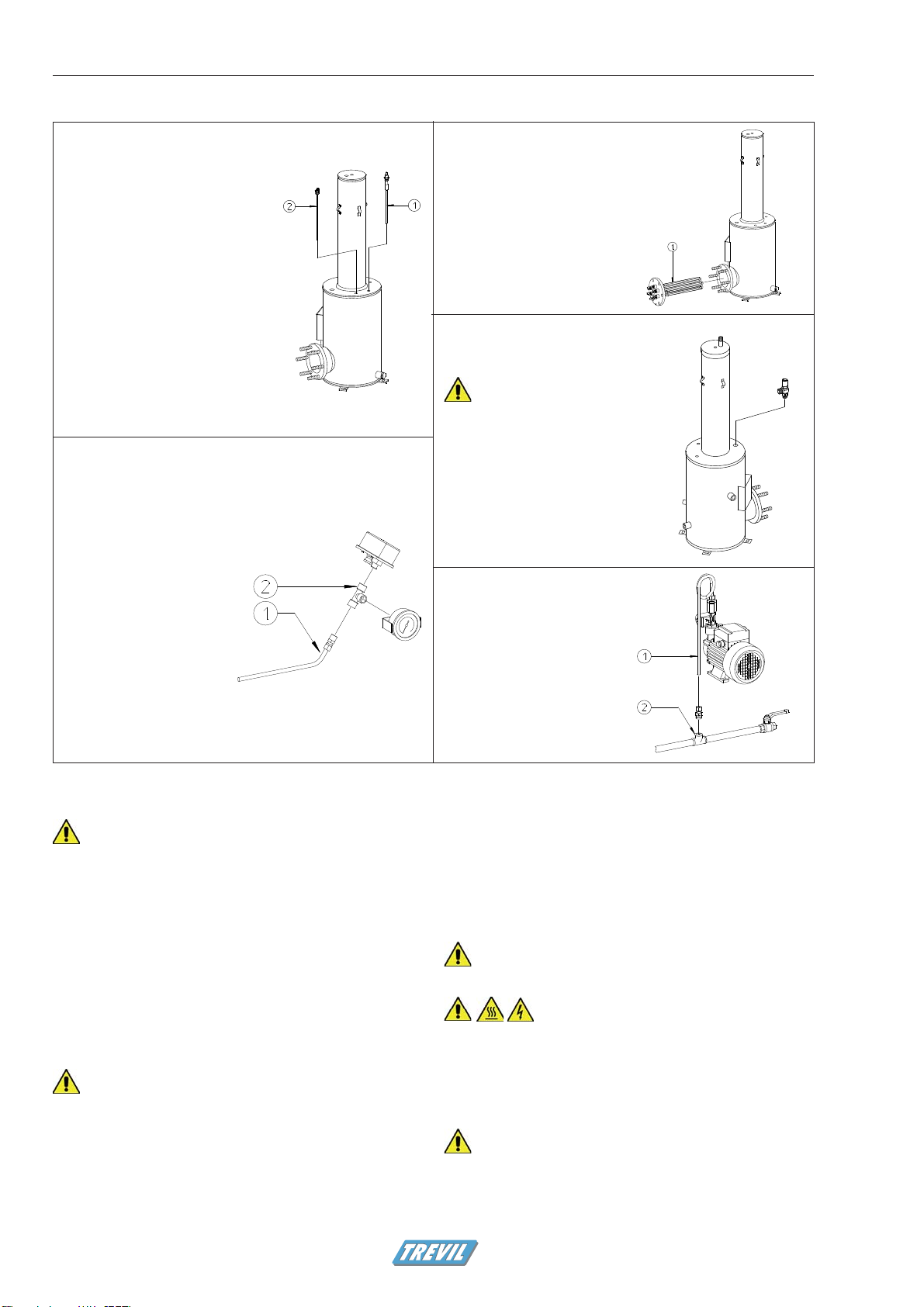
50xx EASYFORM14
Pressure switch, pressure gauge
• Clean the tube 1
• Clean the fitting 2
Safety valve
• Unscrew the safety valve 1
Use caution when handling
the safety valve: do not alter
the setting
• Clean the fitting and the hole
from scaling
Level probes
• Remove level probes 1 and 2
• Remove scaling from the level
probes
Water inlet
• Remove water inlet tube
1
• Clean from scaling
• Clean the water inlet
fitting 2
Heating element
• Unscrew the bolts and
remove the heating
elements flanche
• Clean the heating
elements from scaling
Table 6.1 - Maintenance of the boiler group (only for machine with built-in boiler)
Maintenance
WARNING - Only properly trained operators can dis-
charge the boiler.
If you have doubts about the boiler discharge procedure, ask the
technician to explain it again.
If you feel that the connection of the boiler exhaust to the drainage
is not in good order, do not discharge the boiler and call the techni-
cian.
Boiler discharge procedure :
1. Verify that the connection to the drainage system is firm and
intact;
2. Wait for the pressure in the boiler to be under 1 bar;
3. Lift the metal frame and slowly open the boiler discharge
valve;
4. When the discharge is finished, close the discharge valve and
block it with the metal frame.
WARNING - The boiler discharge procedure is safe only if
the following conditions are verified:
• the boiler discharge valve is safely and firmly connected
to the permanent drainage system
• the pressure displayed by the gauge is lower than 1 bar
6.1.3. Every six months
Call the authorised technician to perform the maintenance operations
described in the following paragraph.
6.2. Maintenance to be carried out by the
technician every six months
WARNING: The maintenance operations described in this
chapter must only be carried out by qualified personnel.
WARNING for the technician:
Before any kind of maintenance or control intervention:
• Disconnect the machine from electricity, air and steam
• Discharge air pressure from the pneumatic circuit by opening
the valve at the air inlet (only for models with sleeves tension-
ing)
• Make sure that all the parts of the machine have cooled down
For types with boiler:
the pump is equipped with a self-
the pump is equipped with a self-
restoring protection.
restoring protection.
Always disconnect power from the
Always disconnect power from the
appliance before servicing the pump: it may restart abruptly.
appliance before servicing the pump: it may restart abruptly.

50xx Easyform-ed0811 ¥
50xx EASYFORM 15
6.2.1. Electrical circuit maintenance
• Verify that electrical connections are properly tightened and do
not show oxidation;
• Verify tightening of solenoid valve coils;
• Verify state of cable and electrical wiring conditions.
6.2.2. Steam circuit maintenance
Model without boiler
• Verify that steam and condensate return connections are
properly tightened and do not leak
• Verify that steam valve is in good working order and does not
present leakage
Model with boiler
• Follow instrucions in table 6.1 for the maintenance of the boiler
group
• Verify that all connections are properly tightened and do not
leak
• Verify that the steam valve is in good working order and does
not present leakage
6.2.3. Air circuit maintenance (only for models
with sleeves tensioning)
• Verify that valves and cylinders do not show any loss of air.
6.2.4. Other controls
• Check that fan blades are free of dirt and lint deposits.
Use only Original spare parts.
50xx Easyform-ed0811
¥
50xx EASYFORM16 Troubleshooting
7. Troubleshooting
7.1. Solution to common problems, allowed to the user
Refer to Table 7.1 for solutions to the most common malfunction situations.
WARNING - DO NOT SERVICE THE APPLIANCE WITHOUT PROPER ADVICE - In event of a malfunction not anticipated in
the table or if the suggested remedy does not solve the problem, do not operate the machine. You must contact a service
center immediately.
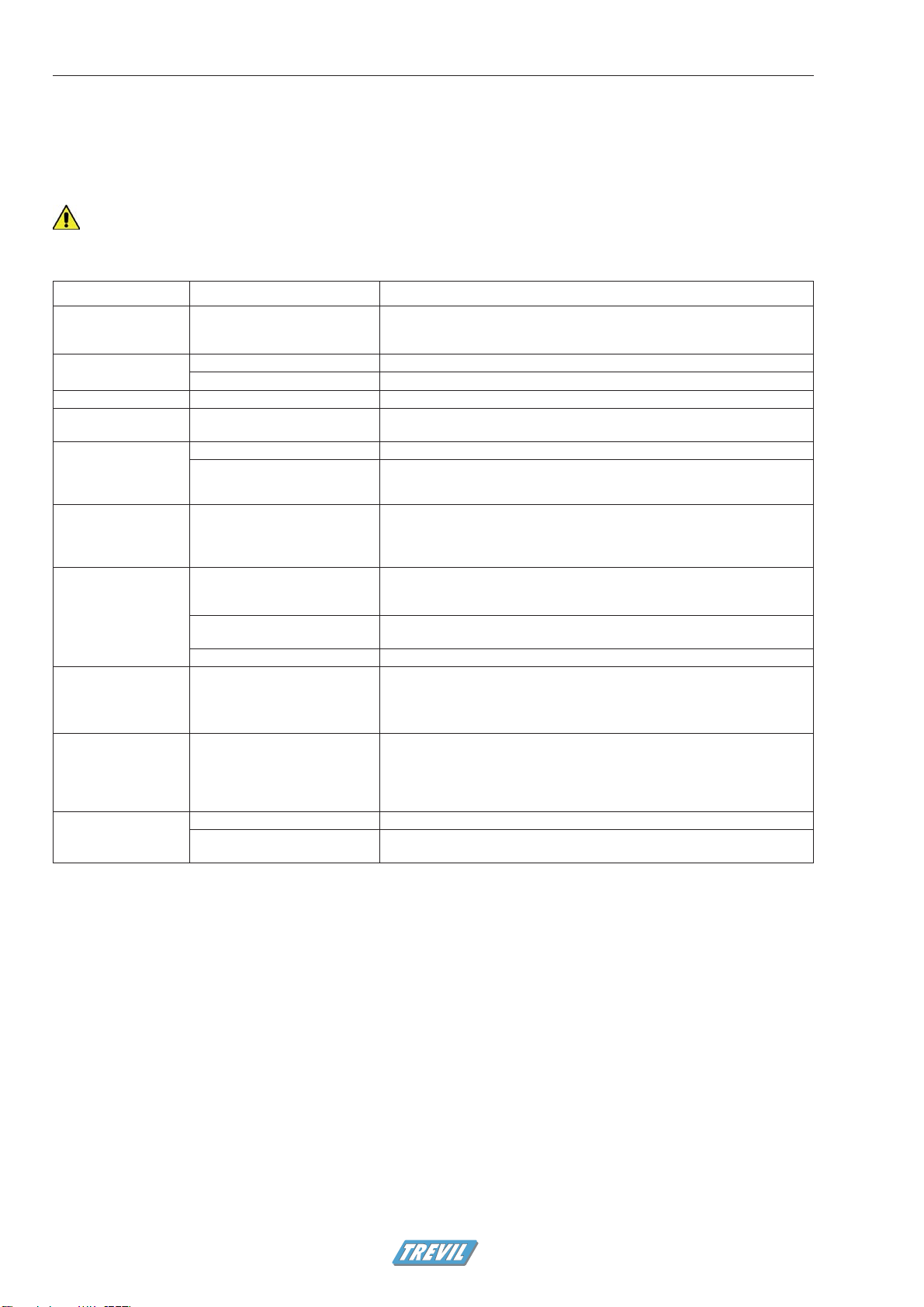
Table 7.1 - Troubleshooting common problems (user)
Problem Possible cause What the user should do
The machine does not
start
No power to the machine Check there is power in the plant
Check connection to the plug
Turn on the main power switch
No steam from the ma-
chine
Steam time set to zero Adjust the steam time
The steam feed valve is closed Open the steam feed valve
Blowing is too weak Lever on the lowest position Shift the lever (5 - Figure 4.1) towards the + sign
Fan does not function
(no blowing)
The blowing time is set at zero Enter programming and set a blowing time
The boiler does not
reach working pressure
(Models 5050, 5055,
5052, 5057)
The heating elements are off Turn on the heating elements switch
The boiler is off Turn on the boiler by means of switch
The boiler reaches
working pressure too
slowly (Models 5055,
5057)
The second heating element is off Turn on all the heating elements. When working pressure has been reached,
unnecessary power can be turned off
The pump is working
but no water gets into
the vessel (Models
5050, 5055, 5052,
5057)
There is no water / the water
delivery valve is closed
Turn off the machine
Make sure that the water is reaching the machine
When the problem is removed, turn on the machine
The filter is dirty Clean the filter
The water inlet system is dirty It is time to call the technician for periodic maintenance
Too much water into
the boiler (Models
5050, 5055, 5052,
5057)
The level probe of the boiler is
dirty
It is time to call the technician for periodic maintenance
The boiler is turned on
but it does not work
(Models 5050, 5055,
5052, 5057)
The appliance has blocked be-
cause water is not reaching in it
Check that the water delivery valve(s) are open
Check that the valves between the tank and the boiler are open
Check that there is water into the line
When the cause has been removed, turn off and then on again the unit to
remove the protection
The sleeve arms do not
move (Models 5042,
5052, 5057)
Air pressure is too low Set the general pressure at 6bar
The sleeve arms are excluded Remove the exclusion by pushing button EXCL ARMS on the control panel,
When the light is off, the arms are activated.
50xx Easyform-ed0811 ¥
50xx EASYFORM 17Troubleshooting
7.2. Solution to failures, for the use of the authorised service center
WARNING - This chapter is for the exclusive use of an authorised technician. For maintenance and replacement of compo-
nents always refer to a service center.
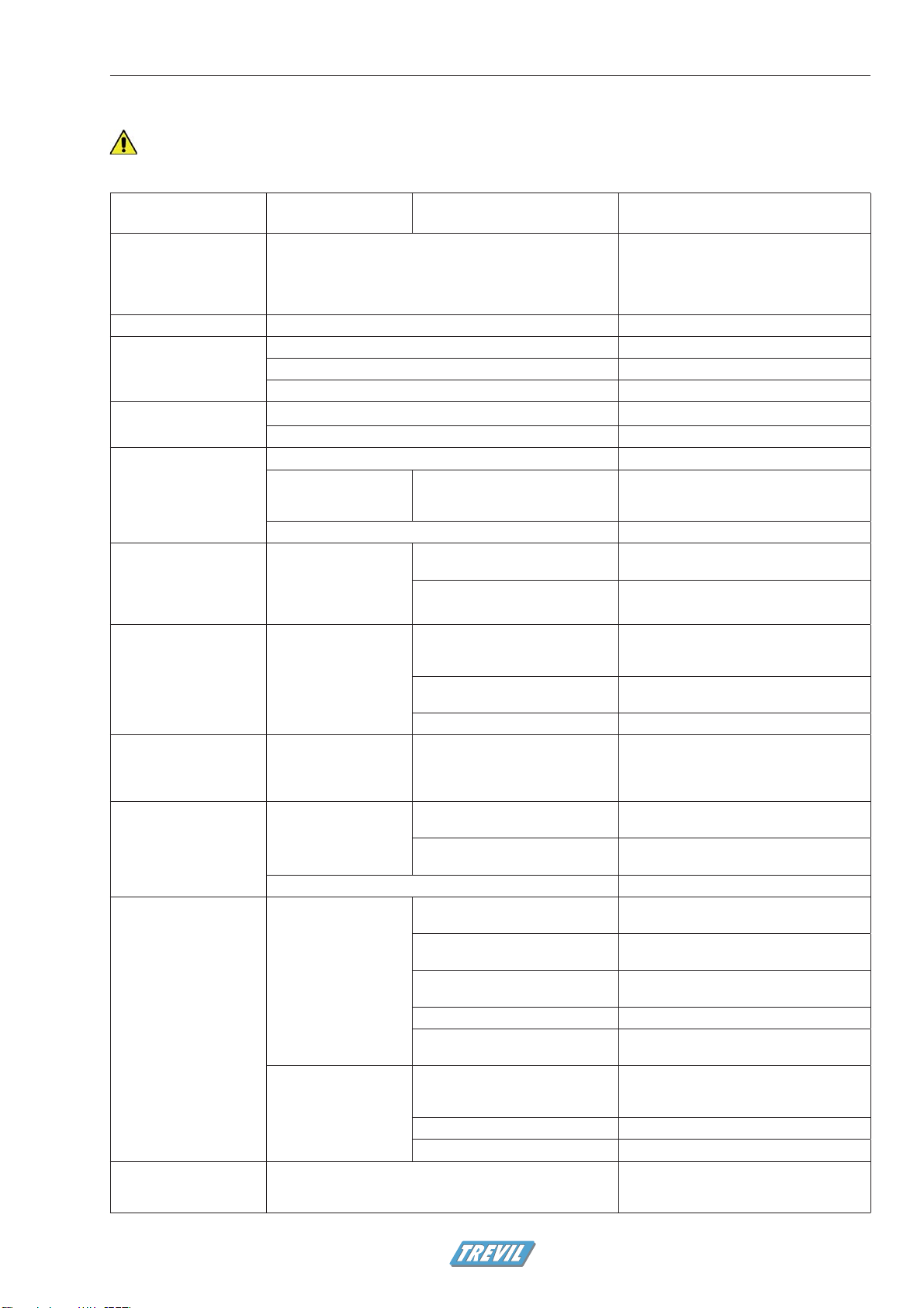
Table 7.2 - Solution to failures
Symptom Components likely to
be involved
Possible cause Controls to be carried out
The programming panel
cannot be activated /
The programming panel
switches on but the machi-
ne doesn’t start
The control card has failed Replace the card
No steam from machine The solenoid valve has failed Replace the solenoid valve
Fan does not function Protection tripped Reset protection
The electromagnetic switch has failed Replace the electromagnetic switch
Motor burnt out Replace the motor
Inadequate ventilation Fan blades has failed Check and replace
Fan is dirty Clean fan
Water leakage during
steam operation
Steam trap failed or dirty (Models 5040, 5042) Replace or clean the steam trap
High water level (Models
5050, 5055, 5052,
5057)
The electic circuit between board and
probes is faulty
Clean the probes
The control board has failed (Models 5050, 5055, 5052, 5057) Replace the card
The pump works, water
gets into the boiler but
overflows fron the safety
valve exhaust. (Models
5050, 5055, 5052, 5057)
The level control board
does not receive the
signal that the level has
been reached
The electic circuit between board and
probes is faulty
Check connections and wires
The control board has failed Replace the board
The pump works but water
does not reach the boiler.
After 4 minutes the unit
turns into protection mode
(Models 5050, 5055,
5052, 5057)
There is no water or the
water flow is too low
Problems of the water line (no
service, closed valves, interruptions
or leaks, ...)
Verify that water reaches the unit in proper
quantity.
Filters or connections are dirty Clean water intake connections and filters as
per instructions in table 6.1
The pump solenoid valve has failed Replace the solenoid valve
The pump is always on,
the heating elements are
on (Models 5050, 5055,
5052, 5057)
The pump does not re-
ceive the signal to stop
The level control board of the boiler
has failed
Replace the board
The pump does not work
(Models 5050, 5055,
5052, 5057)
The pump does not re-
ceive the signal to start
Electric circuit between control board
and pump is interrrupdes
Check connections and wires
The level control board of the boiler
has failed
Replace the board
The pump has failed Replace the pump
There is water in the boiler
but heating elements do
not turn on (Models 5050,
5055, 5052, 5057)
The heating elements do
not receive the signal to
heat
Pressure switch or relative circuit have
failed
Check the circuit and/or replace the pressure
switch
Safety thermostat or relative circuit
have failed
Check the circuit and/or replace the safety
thermostat
The level control board of the boiler
has failed
Replace the board
The coil of the contactor has failed Replace the contactor
The circuit that drives the heating
elements has failed
Check the electric connections of the contactor
coils
No electricity to the heat-
ing elements
The electric circuit that carries
electricity to the heating elements is
interrupted
Check that the fuses are intact
Faulty element Replace the element
Faulty contactor Replace the contactor
The sleeve arms do not
move (Models 5042, 5052,
5057)
The solenoid valve has failed Replace the solenoid valve

50xx Easyform-ed0811
¥
50xx EASYFORM18

50xx Easyform-ed0811 ¥
50xx EASYFORM 19
Figure 8.2. - How to pack the machine for transportation
Figure 8.1. - How to screw the machine to the crate
Machine stop
Disposal of Waste Electric and Electronic
Equipment (WEEE) in the European Union
This symbol on the product or on its packaging indicates that this
product is subject to separate collection and recycling.
It is your responsibility to dispose of your waste equipment by
handing it over to a designated collection point for the recycling
of waste electrical and electronic equipment. The separate collec-
tion and recycling of your waste equipment at the time of disposal
will help to conserve natural resources and ensure that it is re-
cycled in a manner that protects human health and the environ-
ment. For more information about where you can drop off your
waste equipment for recycling, please contact the dealer where
you purchased the product.
8. Prolonged stop, Tran-
sportation or Decommis-
sioning
The following explanation refers to all models, follow only the instruc-
tions relating to the model you own.
8.1. Prolonged stop
In case of prolonged stop of the machine:
1. Model with boiler: discharge the boiler.
2. Close air connections (models with sleeves tensioning).
3. Close steam (models without boiler) or water (models with
boiler) connection.
4. Disconnect from electrical power.
5. Discharge the pressure in the air circuit (models with sleeves
tensioning).
6. Discharge residual condensate.
7. Clean the cabinet and the grids from dust and lint.
8. Protect the form so that the covers do not get dirty.
8.2. Transportation
In case the machine must be moved, follow the instructions below.
1. Model with boiler: discharge the boiler.
2. Close air connections (models with sleeves tensioning).
3. Close steam (model without boiler) or water (model with boiler)
connection.
4. Disconnect from electrical power.
5. Discharge the pressure in the air circuit (models with sleeves
tensioning).
6. Discharge residual condensate.
7. Disconnect all connections (water/steam, air, ...).
8. Clean the cabinet and the grids from dust and lint.
9. Move the machine to a crate of suitable size.
10. Screw the machine to the crate, using suitable brackets (Figure
8.1).
11. Fold any protruding elements (such as the control panel).
12. Protect the form so that the covers do not get dirty.
13. Wrap the machine in cellophane or bubble plastic.
14. If necessary, cover the whole machine with a cardboard box
and tighten it to the crate.
8.3. Decommissioning
At the end of its life the machine must be properly dismantled and its
parts must be disposed of according to local regulations.
1. Model with boiler: discharge the boiler.
2. Close air connections (models with sleeves tensioning).
3. Close steam (model without boiler) or water (model with boiler)
connection.
4. Disconnect from electrical power.
5. Discharge the pressure in the air circuit (models with sleeves
tensioning).
6. Discharge residual condensate.
7. Disconnect all connections (water/steam, air, ...).
8. Move the machine to a crate of suitable size.
9. Screw the machine to the crate, using suitable brackets (Figure
8.1).
10. Fold any protruding elements (such as the control panel).
11. Give the machine to a specialized recycling center for proper
separation and reciclyng of all materials (painted steel, stainless
steel, copper, plastic, cloth).

50xx Easyform-ed0811
¥
50xx EASYFORM20
EV ELETTROVALVOLA
VAPORE SOLENOID VALVE
STEAM ELEKTRODAMPFVENTIL ELECTROVANNE
VAPEUR ELECTROVÁLVULA
VAPOR
FL FILTRO
CONDENSATORE CAPACITOR FILTER KONDENSATFILTER FILTRE CONDENSATEUR FILTRO
CONDENSATORE
FS FUSIBILE FUSE SICHERUNG FUSIBLE FUSIBLE
IM INTERRUTTORE
MACCHINA MACHINE SWITCH MASCHINESCHALTER INTERRUPTEUR
MACHINE INTERRUPTOR
MÁQUINA
PM PEDALE START STARTPEDAL STARTPEDAL PEDALE START PEDAL START
RT RELE' TERMICO THERMAL RELAY THERMORELAIS RELAIS TERMIQUE RELÉ TÉRMICO
VT MOTORE VENTILATORE BLOWING MOTOR GEBLÄSE MOTEUR VENTILATEUR VENTILADOR
VT1 CONTATTORE COMANDO
VENTILATORE BLOWING MOTOR
CONTACTOR SWITCH SCHALTSCHÜTZ GEBLÄSE CONTACTEUR
COMMANDEVENTILATEUR CONTACTO MANDO
VENTILADOR
SC
(Cod.0221417) SCHEDACOMANDO
MACCHINA MACHINE CONTROL
BOARD STEUERUNGSKARTE DES
MASCHINE CARTE COMMANDE
MACHINE TARJETAMANDO
MÁQUINA
Part Descrizione Description Beschreibung Designation Descripción
ELECTRIC DIAGRAM - SCHEMA ELETTRICO ed 4806
Part of: 5040 - EASYFORM 50Hz (without boiler)
400V 50Hz
Diagrams
9. Technical diagrams
The diagrams in this chapter are for the excludive use of the authirized assistance center.
Do not perform maintenance on the machine if not authorized in writing by the Manufacturing Company.
This manual suits for next models
5
Table of contents
Popular Industrial Equipment manuals by other brands


SUHNER
SUHNER Abrasive expert ROTOset 25-R manual

Trox Technik
Trox Technik TFCU Series Operation and installation manual

Busch-Jaeger
Busch-Jaeger Busch-Wachter DualLINE 6813/11 Series operating instructions

ITW
ITW Simco Ion Conveyostat Installation and operating instructions

Keystone
Keystone MGG operating manual

Jäger
Jäger KS2-16/80 manual