SKF GVP-S-025-4 User manual

Grease injection lubrication
system
GVP-S-025-4
Installation and operation manual
Version 01
Date of issue December 2014
Publication number 951-130-453-S025-4
Languages EN
Country/Countries ...

2

Imprint
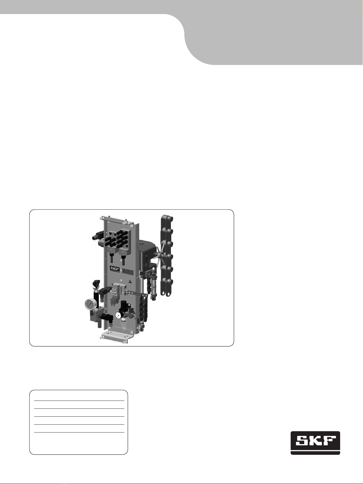
This manual – containing installation, opera-
tion and maintenance instructions complies
with EC-Machinery Directive 2006/42/EC
and is an integral part of the described lubri-
cation system. It must be kept for future use.
This manual – containing installation, op-
eration and maintenance instructions was
created in accordance with the valid stan-
dards and regulations on documentation.
© SKF
This documentation is protected by copy-
right. All rights reserved. The photomechan-
ical reproduction, copying, and distribution
of this documentation or parts thereof by
means of processes such as data processing,
data carriers, and data networks is strictly
prohibited without the express permission of
SKF.
Subject to editorial or technical
modifications.
Service
For all technical questions, please contact:
SKF France
Lubrication Product Division
Bld Charles de Gaulle
B.P. 239
37540 St-Cyr-sur-Loire
FRANCE
Tel. +33 (0) 247 403 087
lubrication-france@skf.com
Or an SKF Service Center, the addresses of
which are given on our website:
www.skf.com/lubrication
Contents
Information concerning the EC Declaration of Conformity and the EC Declaration of
Incorporation...........................................................2
General................................................................3
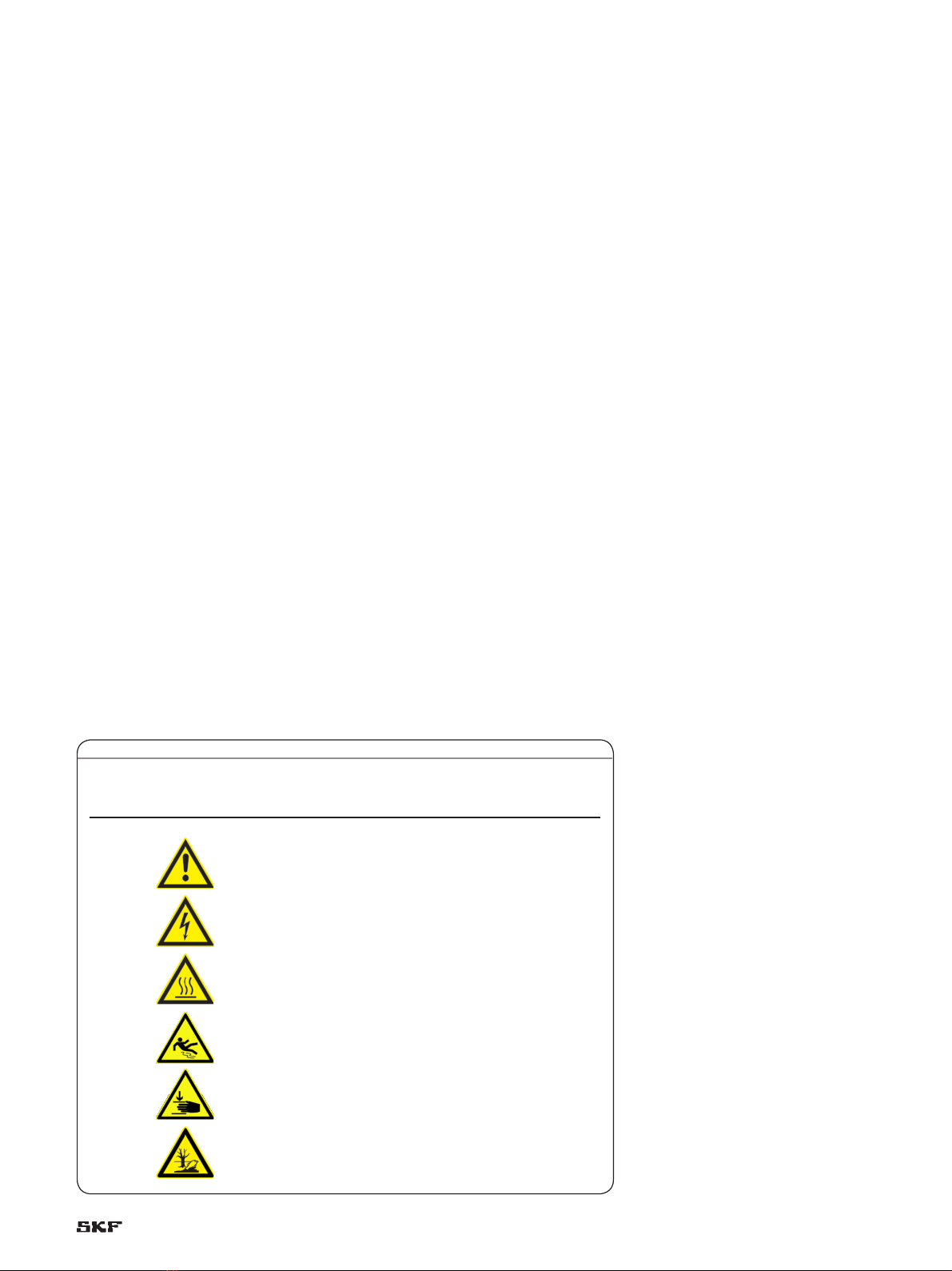
Meaning of symbols and corresponding information ..........................3
1 Safety instructions ....................................................4
1.1 Intended use.......................................................4
1.2 Authorized personnel ................................................4
1.3 Danger relating to electric current .....................................4
1.4 Danger relating to system pressure.....................................4
1.5 Warranty..........................................................5
2. Lubricants ...........................................................5
2.1 General ...........................................................5
2.2 Selection of lubricants ...............................................5
2.4 Lubricants and the environment .......................................6
2.5 Danger relating to lubricants ..........................................6
2.3 Approved lubricants .................................................6
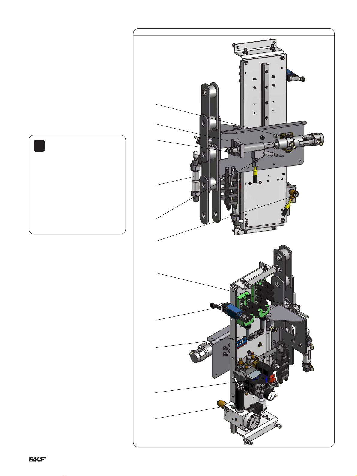
3 Construction and operation .............................................7
3.1 Construction .......................................................7
3.2 Function ..........................................................9
4 Installation instructions ...............................................12
4.1 Positioning and installation ..........................................12
4.2 Mechanical adjustments ............................................13
4.2 Pneumatic connection ..............................................15
4.3 Hydraulic connection ...............................................15
4.3 Electric connection .................................................16
4.4 Proximity switch ...................................................16
5 Transport, delivery and storage.........................................18
5.1 Transport ........................................................18
5.2 Delivery..........................................................18
5.3 Storage ..........................................................18
6 Commissioning.......................................................19
6.1 General ..........................................................19
6.2. Activation ........................................................19
6.3 Modification of the injector metered volume.............................20
6.4.2 Lubrication system bleeding ........................................22
7 Shutdown ...........................................................23
7.1 Temporary shutdown ...............................................23
7.2 Permanent shutdown ..............................................23
8. Maintenance ........................................................24
9. Failures ............................................................25
10 Spare parts. . . . . . . . . . . . . . . . . . . . . . . . . . . . . . . . . . . . . . . . . . . . . . . . . . . . . . . . .26
11 Technical data ......................................................28
1

Information concerning the EC Declaration of Conformity and the EC
Declaration of Incorporation
For the product(s) designated below:
Grease injection lubrication system
Product line:
GVP-S-025-4
SKF herewith certifies that it conforms to the pertinent safety re-
quirements set forth in the following Council Directive(s) for the har-
monization of the laws of the Member States...
• Machinery Directive 2006/42/EC
Note:
1 This declaration certifies conformity with the aforementioned
directive(s), but does not contain any assurance of properties.
2 The safety instructions in the owner’s manual must be observed.
3 The certified product must not be started up until it is confirmed
that the equipment, machinery, vehicle or the like in which the
product was installed meets the provisions and requirements of
the national directives to be applied.
4 Operation of the products on non-standard main voltage as well
as nonobservance of installation instructions can affect the EMC
properties and electrical safety.
SKF further declares that the above mentioned product:
• is meant for integration into a machinery / for connection to other
machinery according to the EC-Machinery Directive 2006/42/EC,
Appendix II Part B. Starting up the product is not permissible until
it is assured that the machinery, vehicle or the like in which the
product was installed meets the provisions and requirements of
the regulations set forth in the EC Directive 2006/42/EC.
• with reference to the EC Directive 97/23/EC concerning apparatus
subjected to pressure, this product must only be used as intended
and according to the Owner’s manual. Especially observe the
following:
–Products of SKF Lubrication Systems France SAS must not be
used in conjunction with fluids, group I (hazardous fluids), ac-
cording to the definition of article 2 paragraph 2 of the Directive
67/548/EC dtd. 27thJune, 1967; and are not approved for ap-
plication with such fluids.
–None of the products manufactured by SKF Lubrication Sys-
tems France SAS can be used in conjunction with gases, lique-
fied gases, pressurized gases in solution and fluids with a vapor
pressure exceeding normal atmospheric pressure (1013 mbar)
by more than 0,5 bar at their maximum permissible
temperature.
–When used as intended, the products supplied by SKF do not
reach the limit values listed in the Article 3 par. 1, sections 1.1 to
1.3 and par. 2 of the Directive 97/23/EC. Therefore, they do not
come under the requirements set forth in annex I of that Direc-
tive. They are not labeled with the CE mark with reference to the
Directive 97/23/EC.They are classified by SKF to come under
Article 3 par. 3 of the Directive.
–The EC Declaration of Conformity and EC-Declaration of Incor-
poration is part of the product documentation.
2

General
Meaning of symbols and corresponding
information
In this manual, the symbols and safety wordings shown on this page
are intended to communicate a particular risk to persons, material
assets, or the environment.
All safety instructions must be respected by person exposed to
these risks. The safety instructions must be communicated to all oth-
er persons.
Instructions attached directly to the equipment, such as
• rotational direction arrows
• fluid connection labels, etc.
must be respected and remain perfectly legible.
It is essential to read these instructions thoroughly and to respect
the safety instructions given.
Table 1
Hazard symbols
Symbol Standard Meaning
DIN 4844-2 W000 General hazard
DIN 4844-2 W008 Voltage
DIN 4844-2 W026 Hot surface
DIN 4844-2 W028 Slippery floor
DIN 4844-2 W027 Risk of hand injury
DIN 4844-2 W55 Risk of pollution
3

!These instructions must be read and understood by all
persons who are involved with the installation, operation,
maintenance, and repair of the product. These instructions must
be kept close to the equipment for future reference.
Note that these installation instructions is an integral part of
the product. It must be handed over to the new operator of the
product if the product is sold.
!In addition to the information provided in the installation
instructions, all generally applicable regulations on acci-
dent prevention and the environment must be observed.
!All SKF products may be used strictly respecting the in-
structions described in this brochure or the operating
instructions.
DANGER!
Working on products that have not been disconnected
from the power supply can cause serious injury or death to per-
sons. Installation, maintenance, and repair work may only be
carried out by qualified experts on products that have been dis-
connected from the power supply. The supply voltage must be
turned off before any product components are opened.
DANGER!
Centralized lubrication systems are under pressure when
they are being operated. Such systems must therefore be de-
pressurized before starting installation, maintenance, or repair
work and before making any changes to the system.
The described product was manufactured in accordance with all
generally acknowledged regulations pertaining to technology, occu-
pational safety, and accident prevention. However, dangers that can
cause physical injury to persons or damage to other material assets
might still occur during the use of the product.
1 Safety instructions
1.1 Intended use
1.4 Danger relating to system pressure
The product is designed for the lubrication of moving conveyor
chains. Other use or use beyond this purpose is considered
unintended.
Products of SKF must not be used in conjunction with substances
and mixtures classified as hazardous by the Annex I part 2-5 of the
CLP regulation (EC 1272/2008), and identified with hazard picto-
grams GHS01-GHS06 and GHS08.
None of the products manufactured by SKF can be used in con-
junction with gases, liquefied gases, pressurized gases in solution
and fluids with a vapor pressure exceeding normal atmospheric
pressure (1013 mbar) by more than 0,5 bar at their maximum per-
missible temperature.
Unless otherwise noted, products of SKF must not be used in con-
junction with explosive atmospheres according to the ATEX-Directive
2014/34/EU.
1.2 Authorized personnel
The products described in the installation instructions may only be
installed, operated, maintained, and repaired by qualified experts.
Qualified experts are persons who have been trained, instructed, and
familiarized with the end product into which the described product is
installed.
These persons are considered capable of such tasks due to their
education, training, and experience with valid standards, conditions,
accident prevention regulations in effect, and installation conditions.
They should be able to carry out the required tasks and to recognize
– and thus avoid – any dangers that might otherwise occur.
A definition of what constitutes a qualified person and who are un-
qualified persons are stipulated in DIN VDE 0105 and IEC 364.
1.3 Danger relating to electric current
The electrical connection for the described product may only be es-
tablished by qualified, instructed persons who have been authorized
by the operator or owner to carry out this task. If the product is im-
properly connected, substantial material or personal damage my be
the consequence.
4

!All SKF products must only be used for their intended pur-
pose and in accordance with the specifications of the in-
stallation instructions for the product in question.
!You must observe the machinery manufacturer's infor-
mation on the lubricants to be used in the machinery.
DANGER!
The manufacturer of the bearing or machinery to be lubri-
cated will specify the lubricant requirements for each point to be
lubricated. You must make sure that the required quantity of lu-
bricant is provided to the relevant lubricating point. If a lubricat-
ing point is insufficiently lubricated, the bearing may become
damaged or jammed.
!If required, SKF can help customers to select suitable
components for the conveyance of the selected lubricant
and to plan and design their centralized lubrication system.
2. Lubricants
2.1 General
The intended use of this product is for the centralized lubrication/lu-
brication of bearings and wear points with lubricants. All physical
limitations of use stipulated in the documentation of the product
such as the owner’s manual, technical drawings and catalogs must
be observed.
More specifically, we call your attention to the fact that substances
and mixtures classified as hazardous by the Annex I part 2-5 of the
CLP regulation (EC 1272/2008), and identified with hazard picto-
grams GHS01-GHS06 and GHS08, can only be used to feed the SKF
centralized lubrication systems, transported or distributed by these
systems after consultation with SKF and obtaining written
permission.
All products manufactured by SKF are not approved for use in
conjunction with gases, liquefied gases, pressurized gases in solution
and fluids with a vapor pressure exceeding normal atmospheric
pressure (1013 mbar) by more than 0,5 bar at their maximum per-
missible temperature.
Should there be a need to use the product to convey media other
than lubricants or hazardous substances, this must be discussed
with SKF first and the company must give express written
permission.
In the opinion of SKF, lubricants constitute a design element that
must be considered when selecting components and designing cen-
tralized lubrication systems. The lubrication properties of the lubri-
cants in question must be considered.
2.2 Selection of lubricants
While the machinery/bearing manufacturer usually specifies lubri-
cants, it is the owner/operator (or maintenance person) who must fi-
nally select the appropriate lubricant, with the help of the lubricant
supplier. When selecting a lubricant, the type of bearing/wear point,
the stresses and strains to be expected during operation, and antici-
pated ambient conditions must be taken into account. All financial/
economic aspects must also be considered.
If you have further questions, you can contact SKF.
We can test lubricants in our own laboratory to establish their
suitability for conveyance (e.g. 'oil separation' behavior) in centralized
lubrication systems.
You can request an overview of lubricant tests offered by SKF from
our Service Center.
1.5 Warranty
The instructions do not contain any information on the warranty.
This can be found in the General Conditions of Sales, which are avail-
able at: www.skf.com/lubrication.
5

DANGER!
Only lubricants that have been approved by SKF for use
with the product may be used. Unsuitable lubricants can cause
product malfunctions and damage to property.
DANGER!
Different lubricants must not be mixed together. Doing so
can cause damage and require extensive cleaning of the prod-
ucts/centralized lubrication system.To prevent confusion, we
recommend that you attach information indicating the lubricant
to be used on the lubricant reservoir.
The described product can be operated with lubricants that comply
with the specifications in the technical data.
Note that some lubricants may have properties that lie within the
permitted limit values and yet not be suitable for use in centralized
lubrication systems for other reasons. For example, some synthetic
lubricants are not compatible with elastomers.
DANGER!
Lubricants can contaminate the ground and watercourses.
Lubricants must be used and disposed of in compliance with the
rules. Instructions and local regulations must be observed when
handling lubricants.
DANGER!
Centralized lubrication systems must be absolutely leak-
free. Leaking centralized lubrication systems can cause a slip
hazard. When performing installation, maintenance, and repairs
test the centralized lubrication system for leaks. Leaky parts of
the centralized lubrication system or components of the lubrica-
tion equipment have to be sealed immediately.
Leaking centralized lubrication systems or components of the lu-
brication equipment are a source of danger in relation to slip hazard
and the risk of injury. These dangers can cause physical injury to per-
sons or damage to other material assets.
Refer to safety precautions in the lubricant manufacturer's mate-
rial safety data sheet.
Lubricants are hazardous substance. It is essential to respect any
safety instructions given in the lubricant safety data sheet. You can
ask the manufacturer of the lubricant for the material safety data
sheet.
2.4 Lubricants and the environment
Note that lubricants are harmful to the environment and flammable;
their transportation, storage, and processing are subject to special
precautionary measures. For specifications on transportation, stor-
age, processing, and dangers to the use and the environment for the
lubricant, refer to the material safety data sheet provided by or avail-
able from the lubricant manufacturer. You can ask the manufacturer
of the lubricant for the material safety data sheet.
2.3 Approved lubricants 2.5 Danger relating to lubricants
6

Fig. 1
GVP lubrication system
1
3
6
2
4
8
5
9
10
11
7
Legend fig. 1
1 Injector cylinder
2 Injector carriage
3 Injector
4 Stop cylinder
5 Analog pressure sensor (forVisioLub*
6 Lubricant inlet
7 Capstan
8 Limit switch (safety)
9 Carriage return cylinder
10 Pneumatic unit (pressure gauge, pressure reg-
ulator, filter)
11 Lubricant treatment unit (pressure gauge,
pressure regulator)
* According to the model and the control unit of
the GVP system
3 Construction and
operation
3.1 Construction
A GVP grease injection lubrication system
includes all the mechanical, hydraulic, pneu-
matic and electrical components required to
lubricate moving conveyor chains.
!Different components can be used
on the GVP system. Their position
can also differ. The main functions are
the same. They might be also some
slight dimension differences.
For further information, please refer to
the technical documentation delivered
with the GVP system or contact the SKF
Service Center.
7

(52)
(5)
725±5
685±5
(655)
745±5
68
95
77
40
~245
151
15
~288
30
M8 (×4)
M8 (×4) (9)
175
155
12,5 45 +0
-2
Ø8 (×4)
74,2+0
-2
421
115
Fig. 2
GVP-S-025-4G dimensions
8

Fig. 3
Example of the lubrication installation for sterilizer
1 Pneumatic control unit
2 Pneumatic drum pump
3 Lubricant drum
4 Control and monitoring unit (here AEP3-GV)
5 Proximity switch
6 GVP grease injection lubrication system
1
3
3
66
7
7 Sterilizer conveyor
Blue line: pneumatic line
Black line: grease line
Brown line: electric cable
5
2
3.2 Function
3.2.1 Lubrication unit
A chain lubrication system comprises the different pneumatic, hy-
draulic, mechanical and electronic components necessary to an opti-
mal lubrication. The figure beneath shows an example of a lubrica-
tion installation. It comprises the following main elements:
• Two GVP lubrication systems. They are mounted closed to the
chain and they inject the lubricant directly in the chain nipples. An
AEP3 control unit controls and monitors them and a drum pump
type PT supplies lubricant.
• An AEP3 control and monitoring unit. It triggers the lubricant
injection according to the signals it receives from the proximity
switch. It monitors the function of the GVP system by means of the
different sensors on the system. It controls also the pneumatic
control unit. For further information above the AEP3 control unit,
please read the instruction manual 951-130-428.
• A pneumatic drum pump, type PT to supply lubricant to the GVP
system. It is actuated by a pneumatic control unit.
• A pneumatic control unit to actuate the pneumatic drum pump.
It is controlled by the AEP3 control unit.
• A proximity switch on the chain to detect the lubrication points. It
sends a corresponding signal to the AEP3 control unit.
9

3.2.2 GVP system
The function principle of the grease injection system for the lubrica-
tion of conveyor chains is more or less the same for all systems.
However some models differ from others by the type of lubrication
points, the number of injection heads, etc.
!In the following description of the GVP system function the
chain runs upwards.
But a sterilizer chain can also run horizontally, downwards or
with a slope. The used GVP system is always design for a given
application.
Start position
• The chain is running
• The GVP system waits
• The carriage with the injector is in its ini-
tial position
• The capstan turns freely with the chain
• No signal from the proximity switch
Detection of the lubrication point by the
proximity switch
• The proximity switch sends a signal to the
control unit of the GVP system
• The control unit triggers a lubrication
• The stop cylinder is actuated and blocks
the capstan
10

Injection phase
• The capstan is blocked by the stop
• The chain moves the carriage with the
injector
• When the carriage starts, the injector cyl-
inder is actuated
• The injector comes in contact with the
roller greaser
Lubricant injection
• The capstan is blocked by the stop
• The carriage with the injector moves in
parallel with the chain
• The injector injects lubricant in the greas-
er of the roller
End of the lubrication phase
• The injection time is over
• The return of the injector cylinder is driv-
en. The injector disengages from the
greaser and comes back to its initial
position
• The return of the stop cylinder is driven.
The stop comes back to its initial position.
• The capstan is not blocked anymore by
the stop and turns again freely with the
chain
• The return of the carriage cylinder is driv-
en. The carriage with the injector comes
back to its initial position.
• When all components are back to their
initial position, the GVP is waiting for the
next injection
!The contact time between the in-
jector and greaser is given by the
control unit that controls the GVP sys-
tem.The injected volume of lubricant
does not depends on the time but on the
metering piston stroke of the injector
(see Modification of the injector metered
volume).
11

4 Installation instructions
The lubrication system described in the mounting instructions may
only be installed, operated, maintained, and repaired by qualified ex-
perts. Qualified personnel are persons who have been trained, in-
structed, and familiarized by the user of the end product into which
the system is installed. These persons are considered capable of such
tasks due to their education, training, and experience with valid stan-
dards, conditions, accident prevention regulations in effect, and in-
stallation conditions. They should be able to carry out the required
tasks and to recognize – and thus avoid – any dangers that might
otherwise occur.
A definition of what constitutes a qualified person and who are un-
qualified persons are stipulated in DIN VDE 0105 and IEC 364.
Before installing/positioning the lubrication system, remove the
packaging material and any transportation safety devices such as
sealing plugs. Keep the packaging material until any and all problems
have been clarified.
Country-specific accident prevention regulations and the operat-
ing and maintenance instructions for the operator must be observed
when carrying out all installation work on machines.
!For the product-specific technical data on a specific lubri-
cation system, see the relevant documentation. If you do
not have access to this documentation, you can request it directly
from SKF.
DANGER!
All installation, setting, maintenance and repair works on
the lubrication system must be carried out only when the con-
veyor is off duty. Working closed to a running conveyor chain may
cause operator's injuries and/or important material damages.
4.1 Positioning and installation
The lubrication system must be protected from vibrations but on the
other hand mounted so that it is easily accessible to ensure that all
further installation work can be carried out without difficulty. Ensure
that there is sufficient circulating air to prevent the system from
overheating. For information on the maximum admissible ambient
temperature, see the technical data section.
Fig. 4
20 mm
!Mounting dimensions
Please refer to the lubrication system general drawing for
the mounting dimensions. This drawing is delivered with the lu-
brication system. If you do not have this drawing, please contact
the SKF Service Centre to get it.
!Moving direction
You have to take in account the moving direction of the
chain when installing the lubrication system. A wrong installation
of the system will lead to the destruction of the system and im-
portant damages on the chain. The moving direction is indicated
with an arrow on the GVP system.
• The lubrication system is mounted on the side of the chain and
fixed on brackets previously fitted by the user.
• The GVP system must be mounted according to the motion direc-
tion of the chain.
• The GVP system has four fixing points.
• The injection head must be at a distance of ca. 20 mm from the
grease nipple (†fig. 4)
• The capstan finger (†pos. 6 fig. 7) must come between the two
inner plate of the chain and must be aligned with the stop head
(†pos. 7 fig. 7).
12

Fig. 6
1
2
4.2 Mechanical adjustments
!The position setting must be carried out at the same time
on both sides of the lubrication system. The adjustment of
only one side of the system may cause material damages on the
lubrication system (misalignment).
DANGER!
Adjustments to the pick-up system must only be made
when the pneumatic feed is shut off and the chain stopped.
The position of the lubrication system must be mechanically adjust to
optimize the lubrication process. Several mechanical adjustment can
be carried out:
4.2.1 Position of the injector
The injector must be correctly centered with regard to the lubrication
point and be at a distance of 20 mm for the greaser. The position of
the injector is set according to three axis (†fig. 5).
4.2.1.1 Axis A
The A axis corresponds to the 20 mm distance between the injector
and the greaser. Do this adjustment when installing the frame of the
GVP system. It is hard to modify it later. Take all necessary measures
to reach the distance.
!The intermediate supports between the GVP system and
the client's machine are the client's responsibility, except if
specified differently.
A
B
C
Fig. 5
4.2.1.2 B axis
• Loosen the 4 locking screws († pos. 1 fig. 6), 2 locking screws on
each side of the GVP system.
• Tighten or loosen the nuts († pos. 2 fig. 6) to position the injector
with regard to the greaser.
• When the injector is aligned with the greaser, tighten the 4 locking
screws († pos. 1 fig. 6).
13

4.2.2 Position of the capstan
It is possible to adjust the position of the capstan fingers with regard
to the chain inner plates, but above all with regard to the stop head
(† fig. 8).
• Loosen the nut (1)
• Loosen the threaded nut (2)
• Screw on or unscrew the nut (3) with regard to the threaded nut
(2) to adjust the position of the capstan.
• Bring the threaded nut (2) in contact the the steel sheet (5) with
the screw (4)
• Tighten nut (1)
Fig. 8
4
5
123
6
7
8
Fig. 7
1
4.2.1.3 C axis
It is possible to adjust a little the position of the injector with regard to
the C axis. Therefore screw on or unscrew the stop head
(† pos. 1 fig. 6) to slightly modify the axis of the capstan finger.
14

4.2 Pneumatic connection
The lubrication system must be connected to the client's compressed
air network.
The compressed air quality must comply with purity class 5 de-
fined by DIN ISO 8573-1:
–Maximum particle size: 40 µm
–Maximum particle density: 10 mg/m3
–Dew point: 7 °C
–Maximum water content : 7 800 mg/m3
–Maximum residual oil content: 25 mg/m3
The air line is directly connected to the air treatment unit
(†pos. 1 fig. 9) with a quick connector for tube OD 8 mm.
The air treatment unit comprises:
• An isolation valve (†pos. 2 fig. 9) to shut down the air supply
• A pressure gauge (†pos. 4 fig. 9) to monitor the pressure and an
turning button (†pos. 3 fig. 9) to adjust the pressure if
necessary.
• A filter (†pos. 5 fig. 9)
!DANGER!
The maximum primary air pressure indicated for lubrica-
tion system operation must not be exceeded.
Fig. 9
1
2
3
5
4
Fig. 10
1
2
3
4
5
4.3 Hydraulic connection
The lubrication system is supplied with lubricant by an external
pump. Connection to the lubricant inlet with a G 3/8 connector, depth
8 (†pos. 1 fig. 10).
The lubricant treatment unit comprises:
• A pressure switch (†pos. 5 fig. 10)
• A safety valve (†pos. 2 fig. 10)
• A pressure gauge to monitor the pressure (†pos. 3 fig. 10)
• A pressure regulator (set and sealed at the factory)
(†pos. 4 fig. 10)
DANGER!
The maximum lubricant pressure indicated for system op-
eration must not be exceeded.
4.3.1 Supply pump
The lubricant supply pump must be located as close as possible to
the GVP system.
In the case the pump supplies simultaneously several GVP sys-
tems, it must be located in the middle of the system to get an equal
length of tubing.
15

4.4 Proximity switch
Proximity switch detects pins of the moving chain.
When a roller is detected the proximity switch sends a signal to the
control unit of the GVP lubrication system. According to the running
lubrication program, the control unit triggers or not a lubrication.
The position of the proximity switch is very important. It makes
possble to trigger a lubrication at the right time so that the injection
head comes in contact with the greaser of the roller.
!For the product-specific technical data the proximity
switch, see the relevant documentation. If you do not have
access to this documentation, you can request it directly from
SKF.
DANGER!
Only qualified, instructed specialists who are authorized by
the operator may install the electrical connections for the lubri-
cation unit. The connection conditions and the local regulations
(e.g. DIN, VDE) must be scrupulously respected. If systems are
improperly connected, substantial material or personal damage
my be the consequence.
4.3 Electric connection
Refer to the electrical documentation supplied with the lubrication
system for information about the electrical connection
(†pos. 1 fig. 11) of the system.
!For the product-specific electric data see the relevant doc-
umentation. If you do not have access to this documenta-
tion, you can request it directly from SKF.
DANGER!
The proximity switches may be connected only by properly
qualified and instructed personnel.
Working on proximity switches under electrical voltage could lead
to personal injury.
4.4.1 Position of the proximity switch
The proximity switch must be above the chain to detect the rollers.
It must be at a certain distance before or after the lubrication sys-
tem.This distance is measured from the axis of the capstan of the
GVP system.
d = n × P
d= distance
n= random whole number
P= chain pitch (distance distance between two lubrication points)
It might be necessary to adjust the position of the proximity switch
according to the chain speed and the system response time. This
manual adjustment is done empirically.
Therefore SKF recommends to use a switch support with an ob-
long hole parallel to the chain to make the adjustment easier.
Fig. 11
External electric connection
1
16

It is important to correctly position the proximity switches in relation
with the lubrication point to guarantee an optimal function. The
proximity switches must be perfectly positioned in the axis of the
point to be detected (†fig. 12).
Metal support
The mounting of the sensor differs if it suits or not for flush mount-
ing in metal († fig. 13).
If the detector is suitable for flush mounting is metal, then no side
clearance is required. But if it is not suitable for flush mounting in
metal, then a side clearance is required.
Sensing distance of the proximity switch
(† fig. 14)
Nominal sensing distance (Sn)
The rated operating distance for which the sensor is designed. It does
not take into account any variations (manufacturing tolerances, tem-
perature, voltage).
Real sensing distance (Sr)
The real sensing distance is measured at the rated voltage (Un) and
the rated ambient temperature (Tn).
It must be between 90% and 110% of the nominal sensing distance
(Sn): 0.9 Sn ≤ Sr ≤ 1.1 Sn.
Usable sensing distance (Su)
The usable sensing distance is measured at the limits of the permis-
sible variations in the ambient temperature (Ta) and the supply volt-
age (Ub). It must be between 90% and 110% of the real sensing dis-
tance (Sn): 0,9 Sn ≤ Su ≤ 1,1 Sr.
Assured sensing distance (Sa).
This is the operating zone of the sensor. The assured operating dis-
tance is between 0 and 81% of the nominal sensing distance (Sn): 0 ≤
Sa ≤ 0,9 x 0,9 x Sn
Fig. 12
Sa : 0 < Sa < 0,81 Sn
Sa Sa
Sensor, flush mounting in metal
metal
metal
metal
metal
Sensor, no flush mounting in metal
object to be
detected
object to be
detected
Fig. 13
Sensing face
H = differential travel
Sa =
assured detection
Standard metal target
Output ON Output OFF
Fig. 14
17

There are no restrictions relating to land, air, or sea transportation.
5.2 Delivery
Following receipt of the shipment, the product or products must be
checked for damage and the shipping documents should be used to
make sure that the delivery is complete. Keep the packaging material
until any and all problems have been clarified.
5.3 Storage
The following conditions apply to the storage of SKF products.
5.3.1 Storage of lubrication units
• Ambient conditions: dry, dust-free environment; storage in well-
ventilated, dry area
• Storage time: 24 months max.
• Permitted air humidity: < 65%
• Warehouse temperature: 10 – 40 °C
• Light: direct sunlight/UV radiation must be avoided; nearby sourc-
es of heat must be screened
5.3.2 Storage of electronic and electrical devices
• Ambient conditions: dry, dust-free environment; storage in well-
ventilated, dry area
• Storage time: 24 months max.
• Permitted air humidity: < 65%
• Warehouse temperature: 10 – 40 °C
• Light: direct sunlight/UV radiation must be avoided; nearby sourc-
es of heat must be screened
5.3.3 Storage – general information
• Ensure that no dust gets into stored products by wrapping them in
plastic film
• Store products on racks or pallets to protect them from damp
floors
• Before placing products into storage, protect uncoated metal sur-
faces - and drive parts and mount surfaces in particular - from
corrosion using long-term corrosion protection.
!The product must not be tipped up or dropped.
5 Transport, delivery and storage
5.1 Transport
SKF products are packaged in accordance with the regulations of the
recipient country and in accordance with DIN ISO 9001. Our prod-
ucts must be transported with care. Products must be protected
against mechanical influences such as impacts. Transport packaging
must be labeled with the information 'Do not drop!'.
18
Table of contents
Other SKF Industrial Equipment manuals

SKF
SKF THKI 300 User manual

SKF
SKF TKBA 40 User manual

SKF
SKF Linkoln WS-E Series User manual

SKF
SKF MonoFlex B Series User manual

SKF
SKF LINCOLN SP/SMB3 Series User manual

SKF
SKF TMBR User manual

SKF
SKF VIBRACON User manual

SKF
SKF SMBM-X User manual

SKF
SKF EP1000 Instruction Manual

SKF
SKF TMHP 15/260 User manual
Popular Industrial Equipment manuals by other brands

Mitsubishi
Mitsubishi Limiservo X G Series Technical information manual

Technom
Technom Lokring MTK400 Instruction card

KINSHOFER
KINSHOFER KM 602 Operator's manual

Erskine Attachments
Erskine Attachments 110X Safety and operating instructions

Niko
Niko 10-803 Product information

profluid
profluid PF70-30DFS Installation & operation manual