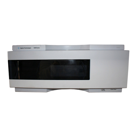
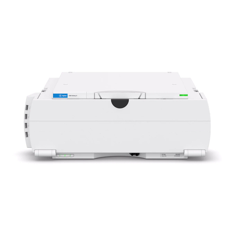
Agilent Technologies 1100 Series User manual

s1
Agilent 1100 Series
Autosampler
Thermostat
Reference Manual
Agilent G1330B
Asset # 304029

2 1100 Series AT Reference Manual
Notices
© Agilent Technologies, Inc. 2002
No part of this manual may be reproduced in
any form or by any means (including elec-
tronic storage and retrieval or translation
into a foreign language) without prior agree-
ment and written consent from Agilent
Technologies, Inc. as governed by United
States and international copyright laws.
Manual Part Number
G1330-90002
Edition
Edition 07/02
Printed in Germany
Agilent Technologies
Hewlett-Packard-Strasse 8
76337 Waldbronn, Germany
Software Revision
This guide is valid for A.01.xx revisions of
the Agilent 1100 Series Autosampler Ther-
mostat software, where xx refers to minor
revisions of the software that do not affect
the technical accuracy of this guide.
Warranty
The material contained in this docu-
ment is provided “as is,” and is sub-
ject to being changed, without notice,
in future editions. Further, to the max-
imum extent permitted by applicable
law, Agilent disclaims all warranties,
either express or implied, with regard
to this manual and any information
contained herein, including but not
limited to the implied warranties of
merchantability and fitness for a par-
ticular purpose. Agilent shall not be
liable for errors or for incidental or
consequential damages in connec-
tion with the furnishing, use, or per-
formance of this document or of any
information contained herein. Should
Agilent and the user have a separate
written agreement with warranty
terms covering the material in this
document that conflict with these
terms, the warranty terms in the sep-
arate agreement shall control.
Techn ology Lice ns es
The hardware and/or software described in
this document are furnished under a license
and may be used or copied only in accor-
dance with the terms of such license.
Restricted Rights Legend
Software and technical data rights granted
to federal government customers include
only those rights customarily provided to
end user Customers of Software. Agilent
provides this customary commercial license
in Software and technical data pursuant to
FAR 12.211 (Technical Data) and FAR 12.212
(Computer Software) and, for Department of
Defense purchases, DFARS 252.227-7015
(Technical Data - Commercial Items) and
DFARS 227.7202-3 (Rights in Commercial
Computer Software or Computer Software
Documentation). If a federal government or
other public sector Customer has a need for
rights not conveyed under these terms, it
must negotiate with Agilent to establish
acceptable terms in a written agreement
executed by all relevant parties.
Safety Notices
CAUTION
A CAUTION notice denotes a haz-
ard. It calls attention to an operat-
ing procedure, practice, or the like
that, if not correctly performed or
adhered to, could result in damage
to the product or loss of important
data. Do not proceed beyond a
CAUTION notice until the indicated
conditions are fully understood and
met.
WARNING
A WARNING notice denotes a
hazard. It calls attention to an
operating procedure, practice, or
the like that, if not correctly per-
formed or adhered to, could result
in personal injury or death. Do not
proceed beyond a WARNING
notice until the indicated condi-
tions are fully understood and
met.
1100 Series AT Reference Manual 3
In This Guide…
1 Theory of Operation
Theory of operation of mechanical hardware, electronics,
and instrument interfaces
2 Installing the G1330B Thermostat
Site requirements and installation of the G1330B thermostat
3 Troubleshooting and Test Functions
The thermostatted autosampler‘s built-in troubleshooting
and test functions
4 Repairing the ALS Thermostat Module
Instructions on repair procedures of the ALS thermostat
5 ALS Thermostat Parts and Materials
Lists for identification of parts and materials
6 Specifications
Performance specifications of the ALS thermostat

4 1100 Series AT Reference Manual

1100 Series AT Reference Manual 5
Contents
1 Theory of Operation
Introduction to the Thermostatted Autosampler 10
ALS Thermostat Operation 12
ALS Thermostat Control and Electronics 14
Temperature Controlled Autosampler Board (TCA) 15
Electrical Connections 17
2 Installing the G1330B Thermostat
Site Requirements 20
Unpacking the Autosampler 23
Optimizing the Stack Configuration 25
Controller Requirements 27
Installing the G1330B Thermostat 28
Stage 1: Preparing the ALS Thermostat and Autosampler 29
Stage 2: Power Cable and Interface Cable Connection 32
Stage 3: Flow Connections 35
Stage 4: Installing the Sample Tray 36
Stage 5: Installing Tray Cover and Front Cover 39
Stage 6: Turning on the Thermostatted Autosampler 40
Stage 7: Update of Control Module Firmware 40
Stage 8: Update of the Agilent ChemStation Software 41
Transporting the Thermostatted Autosampler 43

6 1100 Series AT Reference Manual
3 Troubleshooting and Test Functions
Overview of the Thermostat’s Indicators and Test Functions 46
Status Indicators 47
Power Supply Indicator 48
Instrument Status Indicator 48
ALS Thermostat Error Messages 49
Fan Failed 50
Temperature Control Failed (1 - 4) 51
Temperature Sensor Failed (1 - 4) 52
Lost Contact to ALS Thermostat 53
Power Fail for ALS Thermostat Module 54
Temperature out of Range 55
Bad Cooling / Heating Performance 56
4 Repairing the ALS Thermostat Module
Introduction into Repairing the Thermostat 58
Using the ESD Strap 59
Overview of the Repairing the Thermostat 60
Exchanging the Power Supply Fuses 61
Exchanging Internal Parts 62
Removing the Top Cover and Foam 63
Exchanging Heat Exchanger Fan 65
Exchanging the Heatsink Fans 67
Exchanging the Sensors 69
Exchanging the TCA board 72
Assembling the Main Cover 75

1100 Series AT Reference Manual 7
5 ALS Thermostat Parts and Materials
Main Assemblies 78
Accessory Kit G1330-68705 79
Main Assemblies 80
Foam Parts 81
Plastic Parts 82
Heat Exchanger Fan Parts 83
6 Specifications
Performance Specifications 86
ASafetyInformation
General Safety Information 88
Radio Interference 91
Sound Emission 92
Agilent Technologies on Internet 93
Index

8 1100 Series AT Reference Manual

10 1100 Series AT Reference Manual
1Theory of Operation
Introduction to the Thermostatted Autosampler
The Agilent 1100 Series autosampler is designed for use with other modules of
the Agilent 1100 Series LC system, with the HP 1050 Series, or with other LC
systems if adequate remote control inputs and outputs are available. The
autosampler is controlled from the Agilent 1100 Series control module or from
the Agilent ChemStation for LC systems.
The specially-designed thermostattable sample trays holds either 100 × 1.8 ml
vials or two wellplates and 10 × 1.8 ml vials.
The ALS thermostat contains Peltier-controlled heat exchangers. A fan draws
air from the area above the sample vial tray of the autosampler and is then
blown through the fins of the cooling/heating module. There it is cooled or
heated according to the temperature setting. The thermostatted air enters the
autosampler through a recess underneath the specially-designed sample tray.
The air is then distributed evenly through the sample tray ensuring effective
temperature control, regardless of how many vials are in the tray.
In cooling mode condensation is generated on the cooled side of the Peltier
elements. This condensed water is safely guided into the leak system.

Theory of Operation 1
1100 Series AT Reference Manual 11
Figure 1 Overview of the ALS Thermostat
Power Supply TCA Board
Heat sink fans
Heat exchanger Fan
Condensation leak drain
Heat exchanger
Heat sink

12 1100 Series AT Reference Manual
1Theory of Operation
ALS Thermostat Operation
The thermostatted autosampler is equipped with a cooling/heating module
which uses Peltier elements for efficient air cooling. When turned on the front
side of the Peltier elements is heated/cooled according to the temperature
setting. A fan draws air from the sample tray area and blows it through the
channels of the heating/cooling module. The fan speed is determined
according to the environmental conditions (e.g., ambient temperature,
humidity). In the heating/cooling module the air reaches the temperature of
Figure 2 ALS Thermostat Principle
air channel in
autosampler sampling
unit
special sample tray
air outlet
Peltier elements
heat exchanger
heating/cooling
module
ambient air in
heated air out
thermostatted air

Theory of Operation 1
1100 Series AT Reference Manual 13
the Peltier elements and this thermostatted air is blown underneath the
special sample tray where it is evenly distributed and streams back into the
sample tray area. From there it is again drawn into the ALS thermostat. This
“recycle” mode assures a very efficient cooling/heating of the sample vials.
In cooling mode the opposite side of the Peltier element will become very hot
and to maintain the performance of the elements they have to be cooled down.
This is done with large heat exchangers in the back of the ALS thermostat.
Four fans blow air from left to right through the instrument to remove the
heated air. The fan speed is controlled according to the temperature of the
Peltier elements.
During cooling condensation will appear in the heating/cooling module. The
condensed water will be guided out of the ALS thermostat.

14 1100 Series AT Reference Manual
1Theory of Operation
ALS Thermostat Control and Electronics
The ASM board of the autosampler module provides all control signals for the
ALS thermostat (e.g., temperature setting) and receives the sensor signals
from the temperature and fan sensors.
The TCA board controls the internal assemblies in the ALS thermostat. This
chapter describes the electronics of the TCA board.
Figure 3 Block Diagram ALS Thermostat Electronics
TCA Board
ASM Board
Peltier
Assembly A
Peltier
Assembly B
Peltier
Assemblies
C + D
Temperatur Sensor
Fan 1
12
2345
34
Primary Board
Bridge Rectifier
+ 36 V
Line Voltage

Theory of Operation 1
1100 Series AT Reference Manual 15
Temperature Controlled Autosampler Board (TCA)
The board controls all information and activities of all assemblies within the
ALS thermostat. The operator enters parameters, changes modes and controls
the module through the control module or Agilent ChemStation, that is
connected to the autosampler module. Autosampler and ALS thermostat are
connected via a control cable for signal exchange.
Step Down Switcher
The four Peltier assemblies (A to D) are driven by synchronous step down
switching regulators. Switcher 1 and 2 receive their power (+36V) from the
ALS thermostat internal power supply. Switcher 3 receives its power (+24V)
from the autosampler module via the interface cable. The maximum power
consumption for all Peltier assemblies is approximately 180 Watts in cooling
mode and 120 Watts in heating mode.
Regulators
The fans are equipped with hall sensors that allow to determination of the
actual speed of the fans. The speed of the four heat sink fans is variable and
will be set according to the actual temperature at the heat sink side of the
Peltier assemblies. The heat exchanger fan is always running at highest speed.
the speed will be reduced to a minimum when the sample tray is removed from
the autosampler.
Auto Range
When the ALS thermostat power cable is connected to the module the auto
range circuits checks the connected supply voltage. Default setting is a
connection to a 220-240V supply. If the non-regulated 36V is below a certain
limit the auto range circuit activates a switch on the primary board in the
power supply and switches to 100-120V operation.
Multiplexer
The ALS thermostat is equipped with four digital temperature sensors for
temperature control and diagnostics. Four are used to check the temperature
on both sides of the Peltier elements. The temperature sensor signals and the
signals from the hall sensors in the five fans are the input signals for the
multiplexer. The output of the multiplexer is connected to the autosampler

16 1100 Series AT Reference Manual
1Theory of Operation
main board via the 26 pin autosampler to ALS thermostat cable. The
autosampler firmware checks the signals for correctness and initiates all
needed activities.
EPROM
The EPROM stores all relevant data for the ALS Thermostat (e.g., serial
number, board revision, etc.). This data are pre-set at the factory.
Figure 4 Block Diagram TCA Board
Step Down
Switcher 1
Step Down
Switcher 1
EPROM
Multiplexer
Auto Range
Regulator 3
Regulator 2
Regulator 1
Step Down
Switcher3
PDC 1
+ 36 V
PDC 2
PDC 3
+ 24 V
+ 36 V
Temp. Sensor 1 to 4
Fan Sensor 1 to 5
to ASM Board
Primary Board
Fan 5
Fan 3 + 4
Fan 1 + 2
Peltier Assembly C + D
Peltier Assembly B
Peltier Assembly A
+ 36 V

Theory of Operation 1
1100 Series AT Reference Manual 17
Electrical Connections
WARNING Never use cables other than the ones supplied by Agilent Technologies to ensure
proper functionality and compliance with safety or EMC regulations.
Figure 5 Elctrical Connections
GPIB
RS232C
CAN-bus
Remote
Vial number output
Relay contacts
CAN cable to previous module
CAN cable to next module
Therm-ALS cable
Thermostat -
Autosampler cable

18 1100 Series AT Reference Manual
1Theory of Operation
•The GPIB connector is used to connect the autosampler with a computer.
The address and control switch module next to the GPIB connector
determines the GPIB address of your autosampler. The switches are preset
to a default address (see Autosampler Reference Manual) and this is
recognized immediately after power on.
•The CAN bus is a serial bus with high-speed data transfer. The two
connectors for the CAN bus are used for internal Agilent 1100 Series
module data transfer and synchronization.
•The REMOTE connector may be used in combination with other analytical
instruments from Agilent Technologies if you want to use features such as
common shut down, prepare, and so on.
•The RS-232 connector may be used to control the autosampler from a
computer through an RS-232 connection, using appropriate software. This
connector needs to be activated by the configuration switch module next to
the GPIB connector. The software needs the appropriate drivers to support
this communication. See your software documentation for further
information.
•The Thermostat-Autosampler connection is used for control signal transfer
and synchronization of the two modules. The cable must be installed for
operation of the ALS thermostat.
•The power input socket accepts a line voltage of 100–120 or
220–240 volts AC ± 10 % with a line frequency of 50 or 60 Hz. Maximum
power consumption of the autosampler module is 300 Watts (Volt-Amps).
Maximum power consumption of the ALS thermostat module is 260 Watts
(Volt-Amps).There are no voltage selectors on your autosampler because the
power supplies have automatic selection capability. The autosampler
module has no externally accessible fuses, because automatic electronic
fuses are implemented in the power supply. The power supply of the ALS
thermostat has two externally accessible fuses. The security lever at the
power input socket prevents removal of the autosampler cover when line
power is still connected.
•The interface board slot is used for external contacts, BCD output and for
future use.
WARNING DO NOT disconnect or reconnect the autosampler to ALS thermostat cable when the
power cords are connected to either of the two modules. This will damage the
electronics of the modules.

19
Agilent 1100 Series Autosampler Thermostat
Reference Manual
Agilent Technologies
2
Installing the G1330B Thermostat
Site Requirements 20
Unpacking the Autosampler 23
Optimizing the Stack Configuration 25
Controller Requirements 27
Installing the G1330B Thermostat 28
Transporting the Thermostatted Autosampler 43

20 1100 Series AT Reference Manual
2Installing the G1330B Thermostat
Site Requirements
A suitable site environment is important to ensure optimum performance of
the autosamplers.
Power Consideration
The autosamplers comprises two modules, the autosampler module (G1329A,
G1389A, G1367A, or G2260A) and the thermostat module (G1330B Therm).
Both modules have a separate power supply and a power plug for the line
connections. The two modules are connected by a control cable and both are
turned on by the autosampler module.
The autosampler power supplies have automatic voltage selectors (see Table 1
on page 22). Consequently there are no voltage selectors in the rear of the two
autosampler modules. The autosampler module has no externally accessible
fuses, because automatic electronic fuses are implemented in its power
supply. The ALS thermostat power supply has two externally accessible fuses.
Power Cords
Your autosampler modules are delivered with power cords which match the
wall socket of your particular country or region. The plug on the power cords
which connect to the rear of the two instrument is identical for all types of
power cord.
WARNING To disconnect the autosampler from line power, unplug the power cord from the
autosampler and the thermostat. The power supplies still use some power, even if
the power switch on the front panel is turned off. Please make sure that it is always
possible to access the power plug.
WARNING Shock hazard or damage of your instrumentation can result if the devices are
connected to a line voltage higher than specified.
WARNING Never operate your instrumentation from a power outlet that has no ground
connection. Never use a power cord other than the power cord designed for your
region.
Other manuals for 1100 Series
18
Table of contents
Other Agilent Technologies Thermostat manuals

Agilent Technologies
Agilent Technologies G1330B User manual

Agilent Technologies
Agilent Technologies 1260 Infinity II User manual

Agilent Technologies
Agilent Technologies InfinityLab LC Series User manual

Agilent Technologies
Agilent Technologies 1260 Infinity II User manual

Agilent Technologies
Agilent Technologies 1290 infinity User manual

Agilent Technologies
Agilent Technologies 1290 infinity User manual