AGL GradeLight 2700 User manual

GradeLight 2700
Pipe Laser
Owner’s Manual
AGL Construction Lasers & Machine Control Systems
2202 Redmond Rd., Jacksonville, AR 72076
[email protected] www.agl-lasers.com
Toll Free: 800.643.9696 Phone: 501.982.4433 Fax: 501.982.0880

CONTENTS
General Information .........................................................1-3
Specifications............................................................ 1
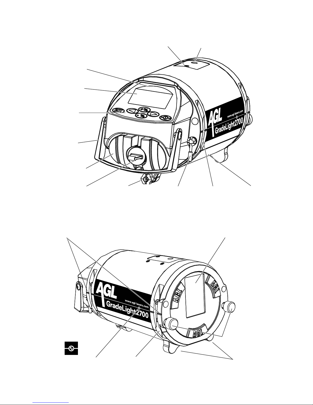
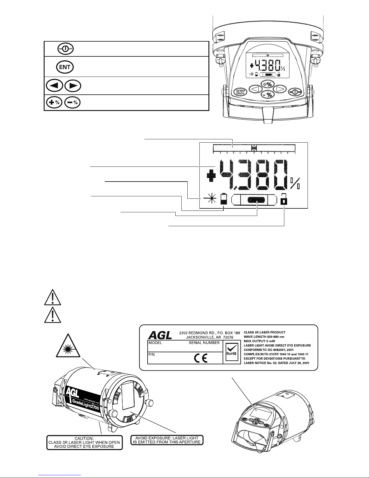
LaserOverview .........................................................2-3
Power ..................................................................... 4
Charging................................................................ 4
Removing the Battery Pack and Using Alkaline Batteries . . . . . . . . . . . . . . . . . . . . . . . . 4
Operation ..................................................................5-9
Pipe Laying Overview ..................................................... 5
Laser Start-up............................................................ 5
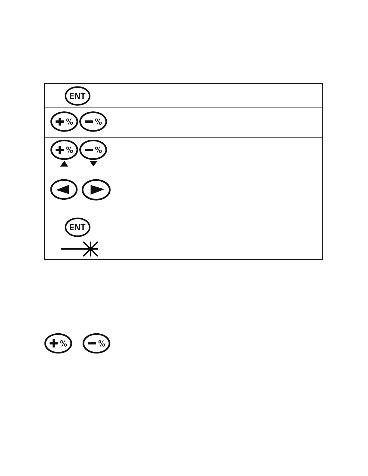
Entering Grade........................................................... 6
Automatic Reset to Zero Grade ........................................... 6
Remote Control and Line Adjustment (Azimuth) . . . . . . . . . . . . . . . . . . . . . . . . . . . . . . . 7
Replacing Batteries in Remote ............................................ 8
Adjustable Leg Set........................................................ 8
Using theTarget .......................................................... 9
BasicSet-upandOperation ................................................ 9
Applications ..............................................................10-16
ElevationTransfer ....................................................... 10
Using an Automatic Level .............................................. 10
Using the SpecialTransit and Rod Group .................................. 10
Alignment Methods.......................................................11
Manhole Mount withTransit..............................................11
SpecialTransitwithRodGroup.......................................... 12
Stringline Method ..................................................... 12
Plumb Bob Method .................................................... 12
Set-up Methods ......................................................... 13
Height Adjustable Legs................................................. 13
ManholeBaseSet-up................................................ 13
In-the-pipe Set-up ................................................... 13
InvertSet-up ....................................................... 14
OpenCutSet-up.................................................... 14
Trivet ............................................................... 15
ManholeBaseSet-up................................................ 15
RodandCrossbraceSystem ............................................ 15
Manhole Set-up..................................................... 15
Above Ground Set-up.................................................. 16
Menu Options ............................................................17-18
Information Available (including software version) . . . . . . . . . . . . . . . . . . . . . . . . . . . . 17
Entering the Set-up Menu................................................. 17
ChangingtheServiceInterval ............................................. 18
DeletingCHECKCALReminder............................................ 18
UsingYour Company Information for the Start-up Screen . . . . . . . . . . . . . . . . . . . . . . 18
Troubleshooting...........................................................19-20
DisplayScreenExplanations .............................................. 19
Using a Blower to Eliminate Refraction...................................... 20
Optional Equipment ......................................................... 20
Checking and Calibration ...................................................21-23
Safety, Care, and Handling .................................................... 24
Warranty ................................................................... 25
Important:
The operator of the GradeLight is expected to follow all operating instructions, periodically
check the accuracy of the unit, and make checks on control as the work progresses. The
manufacturer and its distributors assume no responsibility for improperly controlled work.

GENERAL INFORMATION
The GradeLight pipe laser provides alignment and grade for installation of gravity flow sanitary
and storm sewer pipelines, as well as for pipe jacking and tunneling.
The GradeLight includes:
• Infraredremotecontrol
• Adjustablelegsetformultiplepipesizes
• RechargeableLi-ionbatterypackandsparealkalinebatterycompartment.
Other features include a wide automatic self-leveling range, short length to fit tight inverts,
and adjustable target with magnetic base (included in designated packages).
Specifications
GradeLight
Self-Leveling Range +45% to -15%
Grade Range +40% to -10%
Grade Entry Rolling counter or digit select
Grade Display 0.001%
Azimuth Range Total range: 20 ft. at 100 ft. (6m at 30m)
Accuracy ± 1/16” at 100 ft.
(± 5mm at 100m; ± 10 arc sec.; ± .005%)
Cross Axis Leveling Manual
Beam Type/Output Visible laser diode, 635nm, < 5mW, Class 3R
Environmental IP68; nitrogen purged
Power Supply 1) Rechargeable lithium ion battery pack
2) 110/230V AC converter (charge and run simultaneously)
3) Spare battery compartment for 4 D-cell alkaline batteries
4) Optional 12V power cord
Battery Life at 32° F / 0° C 40 hrs. Li-ion battery; 50 hrs. alkaline
Charging Time 5 hrs. maximum
Mounting 5/8 x 11 (female mounting thread)
Operating Temperature -4° to 122° F (-20° to +50° C)
Storage Temperature -40° to 140° F (-40° to +60° C)
Dimensions Diameter: 5.5” (140mm) / Length: <10.5” (265mm)
Weight 7.6 lbs (3.5 kg) with alkaline battery
Warranty 1 year (2 and 3 Year Optional Warranties Available)
Remote
Operating Range 600’ (190m) front (through the pipe); 25’ (7.6m) from rear
Batteries 3 AA alkaline
Battery Life 2,000 hrs (1 year)
Dimensions 4.7” x 2.35” x 1.2” (119 x 60 x 30mm)
1

Laser Overview
2
Remote
Reception
Window (rear)
LCD Display
Keypad
Handle
Rechargeable
Battery Pack
Charging/Power
Connector Cap
Leg Reference Lines
AlignTo Marks on Legs
Beam Output
& Remote Reception
Window
Securing Knobs For
Adjustable Legs
Feet For 6”
(150mm) Pipe
Adjustable
Leg Slot
Beam’s Horizontal
Centerline
Battery Pack
Release Screw
Toggle Screw to
Tighten Leg
Stringline Hook/
Accessory Mount Line
Pivot Point
Slot For
Adjustable Leg
5/8” x 11
thread

Keypad and LCD Overview
Keypad Functions
Power On/Off
Enter digit select mode for grade
Enter user settings menu
Set azimuth line (left & right)
Change digit positions when setting grade
Set grade as rolling counter or digit select
LCD Indications
Line Adjustment Range Indicator
Shows beam position relative
to line adjustment range.
Grade Entered
Self-Leveling Status
Battery Status
Cross Axis Level Position
Lock Status of Laser and Remote Keypad
The display is backlit for 30 seconds when any button is pressed on the laser or remote.
Safety Labels
The GradeLight is a Class 3R laser, manufactured to comply with the international rules of
safety IEC 60825-1, 2001. Although the power of the emission of the beam is less than 5mW in
Class 3R, the following cautions are recommended:
•Donotstaredirectlyatthebeam
•Donotsetupthelaserateyelevel
3
Made in
U.S.A

POWER
The GradeLight can be powered from the Li-ion rechargeable battery or the alkaline battery
pack. It can also be used while charging -- from AC using the included converter, or from 12VDC
using the optional power cable.
Charging
Charge before first use and when the battery symbol indicates low.The Li-ion battery can
be charged in the unit, or removed and charged separately.This allows you to use alkaline
batteries in the spare battery compartment on the job site while the battery is being charged
elsewhere.
The charging circuit is in the battery pack; the converter with cord allows charging from AC.
Maximum charging time is 5 hours; a microcontroller prevents overcharging.
To Charge the Battery:
1) Connect the converter to the charging/power connector on the battery pack.
2) Select the correct power plug adapter for your country and attach to the converter.
Then plug the converter into a 110V or 220V AC outlet. A green LED indicates power; it
is not a charging indicator.
3) Always place the cap back onto the charging connector to protect from dirt.
The laser can be used while charging, but the charging time may increase (up to 9 hours).
•Donotchargeinwetenvironments.
•Donotusethechargerwithagenerator.
Removing the Battery Pack and Using Alkaline Batteries
The rechargeable battery pack can be replaced with the alkaline battery compartment or an-
other Li-ion pack.Turn off the laser. Turn the release screw under the battery pack to remove it.
If using the alkaline battery compartment, insert 4 “D” cells, noting the polarity indications on
the outside of the case.
NOTE: If the laser has been stored for a while, hold the ON button for at least 3
seconds when starting the unit.
4
Purge screw under black decal
inside battery compartment
DO NOT OPEN!
If this screw is removed, the moisture-free
nitrogen purge of the unit will be lost.
Connector for
charging or for
optional 12VDC
power cord
Battery Pack
Release Screw

Cross axis
not level
Cross axis
is level
5
&
OPERATION
Pipe Laying Overview
The three basic steps to successfully set up the GradeLight for laying pipe are:
A. Dialing in the correct grade.
B.Transferring the elevation to position the laser at the correct height.
C. Aligning the laser beam to the forward manhole.
Before Starting
Attach the necessary mounting accessories, such as the handle/rod mount, trivet, legs, etc. to
the unit. Power-up the unit and adjust the line control to the center of its range.
At the beginning of a pipe laying job, consider the following tips for improved performance:
•TheGradeLightcanbeusedtocheckthehubspriortoactuallystartingthework.Thisisan
opportunity to catch potential errors before using the hubs as a reference to lay pipe.
•Placegraderodormarkerattheforwardmanholeforaplacetoalignto.
•Whenthelastjointofpipehasbeenlaidapproachingamanhole,bringtheGradeLight
forward so that as soon as the manhole is in place, you can set up again without delay.
Laser Start-up
Press On/Off button to power-up the laser.
Check the following indications on the LCD:
The start-up screen shows AGL.
The battery capacity is displayed. Charge when there is one bar left.
The laser automatically self-levels, and returns to the same grade and
line settings as last used. If the LCD laser beam symbol is flashing, it’s
still leveling. When the symbol is lit solid, the laser has leveled and is
ready for use.
Likewise, the beam emitted from the unit flashes until it has leveled.
Check the electronic cross axis vial. If it’s out-of-level, rotate the laser
slightly to the left or right to level the cross axis.
The bubble should be between the lines on the vial.
Before each setup, center the beam using the laser keypad (press both
arrows simultaneously for 2 seconds) or the remote (press CL button).
Center beam with:
Laser keypad
or remote:

Entering a Grade
The grade range is from +40% to -10%. Grade can be set in increments as small as .001% using
the digit select or rolling counter entry method.
The display lights when entering grade.The LCD is color coded to match the grade entry
button: green for positive grade and red for negative grade.
Digit Select Grade Entry
Press ENT.
The first digit flashes.
Select positive or negative grade.The first digit will continue to
flash.To the left of the decimal is a whole unit of per cent grade; to
the right of the decimal are tenths, hundredths, and thousandths.
Change the value of the first digit with the grade buttons (+ to
increase, —to decrease). For large changes hold the button.
Use the azimuth left or right arrows to move through the digits and
to choose the next digit to be changed.The digit you’re working
with will flash like a computer cursor. Use the +and —buttons
again to change the value.
After the desired digits have been chosen, press ENT to save, and
begin the grade that’s been set.
The LCD beam symbol flashes until the grade setting is reached.
Rolling Counter Grade Entry
For a positive grade, hold the +button for 15 seconds or more. After you release, it will auto-
matically increase in grade until you push either the +or —button again to stop.
For a negative grade, hold the —button as described above.
Automatic Reset to Zero Grade
Press both the +and —buttons simultaneously to automatically set the grade back to 0.000%.
6
Increase Decrease
&

Remote Control Overview
The remote is used primarily to move the beam left or right, within the azimuth range, and
to put the laser in standby or locked modes. Since it’s an infrared line-of-sight device, there
should be no obstructions between it and the laser. It can be pointed at either the front side
(through the pipe) or the back side of the laser.
Remote Keypad Functions
Standby Mode
•Pressandhold2seconds.Thisputslaserinstandbymodetosave
battery life during breaks. LCD on laser will show sleep symbol.
•Pressagaintoreturntonormaloperation.Allsettingsareretained.
Reset Line to Center
Hold 2 seconds, and laser beam automatically moves back to center
azimuth position.
Line Adjustment
(left and right azimuth control)
When using remote from the target side, beam moves in the direction
of the arrows. If using remote from laser keypad side, beam moves in
the opposite direction.
Activates Lock Function
All buttons on the remote and laser are blocked, preventing uninten-
tional changes when the laser is in use. LCD on laser shows a lock
symbol. To deactivate: Press the lock button again.
LED for Line Pivot Point
Press to turn on LED on top of laser, which is used for alignment out-
side of the manhole. Automatic shut-off after 1 minute.
Line Adjustment
The laser beam can be aligned to the target using the left and right line adjustment.The
azimuth indicator on the LCD shows the beam position in the adjustment range. Before each
setup, center the beam to allow maximum adjustment in each direction.The total range of
movement is 20’ at 100’ (6m at 30m).
To Move the Beam
Use arrows on the laser keypad or remote. Movement will start slow and speed up as long as
the button is pressed.
7
Compartment for
3 AA batteries
(back side)
Infrared output:
aim at capture
window of laser LED flashes when any
button is pressed.
-- Green: normal
-- Red: low remote battery

To Automatically Center the Beam
On laser keypad, press simultaneously &
On remote, press
Replacing the Batteries of the Remote Control
The LED on the remote will flash red when the batteries are low.To change the batteries:
1. Open the housing by removing the 6 screws.
2. Take the back case off and replace the
batteries, matching the polarity indications.
Use AA alkaline batteries of the same type;
do not mix new and old batteries, as their
lifetime will decrease.
3. Before closing, check that the seal is free of
dirt, to ensure it remains waterproof.
4. Close the housing and tighten the 6 screws
so it’s watertight.
Adjustable Leg Set
One leg set covers multiple pipe sizes.The adjustable “slide leg system” allows the user to set
centerline in 8”, 10” and 12” pipe (200, 250, and 300mm with the metric leg set).The legs can
also be adjusted to non-standard heights.
The three-leg design provides stability when setting up on uneven, rough surfaces.
To attach legs:
1. Use curved centerline leg at rear (keypad end) and
two side legs at front.
2. Slide each leg into the slot on the housing.
3. Match the red reference marks on the housing to red
mark on leg.There are 3 reference marks: 8”, 10”, and 12”
(200, 250, and 300mm).
4. Tighten front legs with thumb screws, and single leg
with toggle screw.
Note:The legs will then be aligned for use in a pipe’s curved surface, where the two side legs
need to be shorter than the center leg. If you are setting up on a flat surface, adjust the legs
differently to level the unit.
For 6” pipe (150mm), use the unit’s built-in feet. A long leg set is available as an optional acces-
sory for 15” to 24” pipe (with a metric leg set for 375 to 600mm pipe).
8

Using the Target
The target can be used for multiple pipe sizes. It features
a unique design: the target panel is mounted at the front
of the base, not in the center.This allows you to view
it easier at the front of the pipe. It also has a magnetic
base for attaching to trench box side wall after pipe set-
ting for better airflow, to minimize refraction.
Alignment notch for 6”, 8”, or 10” pipe
Alignment notch for 150, 200, or 250mm pipe
Level vial
Magnetic attachment (underneath)
Basic Set-up And Operation
The steps noted below are illustrated in previous sections. See next section for specific applica-
tions.
1. Attach any mounting accessories to the unit, such as the legs, trivet, handle/rod mount,
etc. Place it in the manhole or pipe at the proper offset and elevation.
2. Power-up the laser. Swivel it left or right so that the cross axis is level. Check the vial on
the LCD (see p. 3). Set the desired grade.
3. Adjust the target plate to the correct pipe diameter. Place the target in the opposite end
of the pipe and level it using the vial.
4. Adjust line to the center of its range with the remote by pressing the centerline button
or by pressing both line adjust buttons simultaneously. Use the remote to align the
beam to the target.
5. Lift pipe up or down until beam is in the middle of the target bull’s-eye; the pipe is
then on line and at the desired slope.
9

APPLICATIONS
Transfer of Elevation
Using an Automatic Level
1. Mount the level on a tripod outside the manhole
or open cut. Adjust it to level and point at the
manhole hub.Take a reading from a rod held at
the hub.This reading is sometimes called the
“back-sight” reading. (Figure A)
2. Now take a rod reading at the manhole center. If
a manhole is in place, read the elevation of the
base. In an open cut it is necessary to place an
object in the cut which can be used as a refer-
ence. A brick, stone, or board placed at manhole
center will work for marking a reference eleva-
tion, and as a starting point for the placement of
the laser or the trivet.
Using the Special Transit and Rod Group
This is an ideal method to use when the offset hub
is too far from the manhole center to transfer
elevation with a batter-board or other means.
The SpecialTransit is set up using the Rod and
Crossbrace System. (Figure B)
1. Mount the SpecialTransit on the calibrated rod
and point it to the manhole hub.The top edge
of the transit mounting bracket is the elevation
reference and is the same as the horizontal
crosshair (centerline) of the transit.
2. Level the transit using the adjust knob and the
level vial. Use the forward marker knob to adjust
the transit so that it is pointed exactly to an
engineer’s rule or calibrated rod section held at
the manhole hub.
3. After reading the engineer’s rule or calibrated
rod, measure down from the top edge of the
transit mounting bracket (transit centerline) to
the correct invert elevation.
HI
HUB
ROD
1st reading
2nd Reading
Elevation of
Manhole Base
Figure A
Figure B
10

Alignment Methods
After the laser is set up at the correct elevation and the
correct grade is entered, the last step is to align the beam
to the forward manhole using one of these methods:
1) Manhole Mount withTransit
2) SpecialTransit and Rod Group
3) Stringline
4) Plumb Bob
ManholeTransit Method
This method can be used with the SpecialTransit or any
standard transit (ideally one that has a back sight – flop
– capability). Use the ManholeTransit Clamp system to
support the transit.The laser is set up in the manhole using
leg sets, or the trivet.
1. Secure the Clamp Body and Mast (Figure C). Position
the clamp (1) over the top edge of the manhole so the
mast (2) is plumb enough to easily level the transit
when mounted.Tighten the clamp screw (3), until the
clamp points are firmly embedded in the sides of the
manhole.The mast can be further adjusted to plumb
using the lever (4) locking the mast pivot.
Secure the Arm - Slide the arm clamp support (5) and
the arm clamp (6) over the mast and secure. Insert the
arm (7) into the clamp.The clamp allows complete
flexibility to raise, extend, and position the arm so the
transit mount (8) is over the manhole center.The transit
mount is a 5/8 x 11 male attachment for mounting a
standard transit.The AGL SpecialTransit is mounted,
using an adapter assembly.
Aligning the beam with the AGL SpecialTransit
2. Mount the SpecialTransit and adapter to the mount at the end of the arm. Adjust the arm so the
transit is roughly over pipe centerline and in line with the laser (Figure D). Adjust the vertical
crosshair exactly to the forward manhole marker using the forward marker knob.
3. AlignTransit to Laser -Tilt the transit down and sight the line pivot green LED. On the transit,
use the laser centerline knob to adjust the vertical crosshair until aligned exactly with the green
LED. Repeat steps 2 and 3 until the vertical crosshair is on both the forward manhole marker
and the green LED on the unit.
4. Align the Laser Beam to theTransit - Place a target in the ditch approximately 15’ (5m) in front
of the laser. Looking through the transit at the target, adjust the beam left or right using the
alignment buttons on the remote control until exactly centered on the vertical crosshair.You
should then be able to swing the transit from the beam, to the green LED, and to the forward
manhole marker, with each being aligned to the crosshair (Figure E). Repeat steps 2, 3 and 4 if
necessary. When all three are accurately aligned, pipe laying can proceed.
1
2
3
4
5
6
8
7
5
Figure C
Figure D
11
34
2
Figure E

Aligning the beam with a standard transit
Align theTransit over the Instrument - Mount the standard
transit to the transit mount at the end of the arm. Using a
plumb bob, adjust the arm so the transit is directly over the
centerline of pipe. Level the transit. Position the laser so the
line pivot LED is exactly under the plumb point.
Align theTransit to Forward Manhole - Pivot the transit until
the vertical crosshair splits the forward manhole marker.
Align to the Beam using step 4 above.
Special Transit Method
This method uses the Rod and Crossbrace system
The laser is mounted with the Handle/Rod Mount (Fig F).
1. Mount the SpecialTransit - With the rod plumbed, and laser
leveled, mount the SpecialTransit on the rod. Position the
transit where it is possible to see the forward manhole
marker, yet as low as possible on the rod. Secure the rod
mounting bracket with the secure knob.
2. AlignTransit to Forward Manhole Marker - Use the forward marker knob to adjust the vertical
crosshair until it is aligned with the forward manhole marker.
3. AlignTransit to Laser -Tilt the transit down and sight on the green LED. On the transit, use the
laser centerline knob to adjust the vertical crosshair until it is exactly aligned with the green
LED on the laser. Repeat steps 2 and 3 until the crosshair is on the forward manhole marker
and the green LED.
4. Align the Laser Beam to theTransit - Place a target in the ditch approximately 15’ (5m) out in
front of the laser.Tilt the transit down to view the target. Adjust the beam left or right using
the line adjustment buttons on the remote until the beam is exactly centered on the vertical
crosshair.
You should be able to swing the transit from the beam, to the green LED, or forward manhole
marker, with each being exactly aligned to the crosshair. Repeat steps 2, 3, and 4 if necessary.
When all three are accurately aligned, pipe laying can proceed.
Stringline Method
The stringline provides a quick, easy method of beam alignment. Place a target in the ditch
approximately 50’ (15m) out from the laser. Attach a string to the eyelet hook, located on top of
the GradeLight and keeping it plumb, hold it taut, vertically
above the unit (Figure G).
Stand behind the string and visually center it on the forward
manhole. Lower your gaze to the target and use the remote
control to adjust the beam left or right until exactly centered
behind the stringline.
When you can see the stringline centered on the forward
manhole marker and on the beam in the ditch, alignment is
complete.
Plumb Bob Method
This method of alignment can be used if the cut is not too
deep and the wind is relatively calm.The laser must be set up
at the correct elevation and exactly on pipe centerline. Place a
target in the ditch approximately 50’ (15m) out from the laser.
Measure over from an offset hub to the pipe center line and
drop a plumb bob down to the target.
Mark where the plumb bob strikes the target and adjust the
beam left or right until it is centered on the plumb mark.
Figure F
12
Forward
Manhole
Marker
Stringline
Held
Vertical
Target
Stringline
Hook
Figure G

Set-up Methods
These instructions describe four ways to
set up: height adjustable legs, trivet, rod
and crossbrace, or above ground on a
tripod.
Height Adjustable Legs
The adjustable legs can be used to set up
in a manhole base, pipe, invert, or open
cut.
Manhole Base Set-up
1. Prepare laser for use: Attach leg set
with centerline leg at front and two
side legs at rear. Apply power, center
the line adjustment, and enter the
desired grade.
2.Transfer elevation from the hub to the manhole base.
3. Set the front (centerline) leg to the desired height: After determining the desired beam
height above the manhole base, adjust the front leg so the beam will be projected at that
height.
4. Set the unit in place: Position the point of the front leg on pipe centerline, 2” (5 cm) in front
of the manhole center, toward the pipe being laid for accurate alignment. (Figure H)
5. Roughly level the instrument by loosening the rear leg knobs and sliding the unit up or
down, then tighten.
6. Align laser to the forward manhole (see previous section on “Alignment”).
7. Recheck for level and accurate grade setting and proceed to lay pipe.
In-the-pipe Set-up
When setting up in-the-pipe, be sure the joint of pipe used for the set-up is accurately placed
for line and elevation.
Set-up in 6”(150mm) pipe:
1. Remove the handle/rod mount and legs, if attached. Apply power, center the line adjustment,
and enter the desired grade.
2. Slide the unit into the pipe. It should rest on the three fixed short leg points of the housing.
Rough level the unit in the cross axis direction if necessary, using the lighted cross-axis level
vial on the rear control panel.
3. Align the beam to the forward manhole using the remote line control, or the line adjustment
buttons on the unit.
Set-up in 8”, 10”(200mm, 250mm) and larger pipe:
1. Remove the handle/rod mount if attached. Apply power, center the line adjustment, and
enter desired grade.
2. Attach the leg set with two side legs at the front and the centerline leg at the rear. Set all
three legs so the appropriate pipe size mark is aligned with the centerline-of-beam mark
beside each leg slot.
3. Slide the unit into pipe and rough level in the cross-axis direction using the cross-axis level
vial on the control panel.
4. Align the beam to the forward manhole using the remote line control, or the line adjustment
buttons on the unit.
5.The beam should be projecting at pipe centerline. Allow the unit to self-level, then lay pipe.
NOTE: If you prefer, you can use the 6” (150mm) for ALL in pipe set-ups as long as you
remember to reference the lower offset to the gravel and trench excavation depth. What
is important is that the beam elevation from the invert and the target centerline elevation
from the invert is the same.
13
Manhole
Center Place Front
Leg Point here
2"
5cm
Direction
Laser
Pipe
Figure H

Invert Set-up
Position the legs the same as you would if setting up
inside the pipe. Place the laser in the invert and complete
the set-up as shown in the Manhole Base Set-up in the
previous section.
Open Cut Set-up
When using the height adjustable legs in an open cut,
a stable base such as a concrete block, brick, or board
must be placed in the cut at the manhole center and
marked. This is best done when transferring elevation
(see page 10).
Place one of the blocks at manhole center.The front
leg will be positioned on this block 2” (5 cm) in front of
the center mark for critical high accuracy, or on top of
a centerline hub for most applications. Place the other
blocks, etc. so that they provide support for the rear legs
(Figure I).
Set up the unit for laying pipe as described in Manhole
Base Setup in the previous section.
Invert Peg Set-up (Open Cut)
This method is commonly used in open ditches.The cut
should be excavated approximately 6” (150mm) below
invert elevation. (Figure I)
1. Place a stake at the invert elevation.
2. Prepare the laser for use: apply power, center the line
adjust range, and enter the desired grade. Attach the
leg set with the centerline leg at the front and two side
legs at the rear.
3. Set the front centerline leg for correct pipe size using
the marks on the legs.
4. Place the laser in the trench with the single front leg
on the stake (peg). Rest the rear legs on blocks, bricks,
or the ground.
6. Align the beam to the forward manhole.
7. Recheck for accurate grade settings and a level unit.
Proceed to lay pipe.
NOTE: In open cut set-ups the optional long leg set is
usually required.
14
Beam Centerline
Manhole
Invert Elevation
Figure I

Trivet
Manhole Base Set-up
1. Prepare the laser for use: Attach handle/rod mount,
apply power, center the line adjustment, and enter
desired grade. Mount the height adjustable rod (center
the rod height in its adjustment range) to the trivet.
(Figure J)
2.Transfer elevation from the hub to the manhole base.
3. Position the trivet over the manhole center: Place the
front leg of the trivet on the centerline-of-pipe, 5” (13
cm) in front of the manhole center mark.
4. Secure the laser to the rod at the approximate
elevation where the pipe centerline will be.
5. Allow the unit to self-level.
6. Use the height adjustable rod to precisely adjust the
beam elevation.The centerline of beam marks on the
side of the unit are also convenient for establishing
elevation.
7. Align the beam to the forward manhole. Recheck all
the alignment steps to assure accuracy. Check that the
unit is level with an accurate grade setting. Proceed to
lay pipe.
Rod and Crossbrace System
1. Prepare the laser for use: Attach handle/rod mount, apply power, and center the line
adjustment.
2. Mount crossbrace inside the manhole, perpendicular to the centerline of pipe being laid.
Use the level vial on the crossbrace to position it level. Holding the two points firmly against
the manhole wall, extend and tighten the adjusting screw point against the opposite wall.
Tighten until the crossbrace is solid, with the points planted firmly into the concrete.
3. Secure alignment element to the crossbrace using the secure knob. Hang the alignment
element on the crossbrace so that the line control and front secure knobs face the forward
manhole. Measure manhole width where the crossbrace is mounted and use the center
as reference. Place the right edge of the alignment element 2 1/4” (57mm) left of manhole
center.
4. Slide the calibrated rod with the point attached through the alignment element, plumb it
using a hand level, then tighten the secure knob.
NOTE: Pull up on the crossbrace as you tighten the alignment element, then release after it
is tight.This places downward tension on the rod and increases its stability.
5. Establish invert elevation and beam height (see previous section on “Transfer of Elevation -
SpecialTransit Method”).
6. Secure the laser to the rod at the correct elevation and allow the unit to self-level.
7. Align beam to the forward manhole (see previous section on “Alignment – SpecialTransit
Method”). Recheck alignment steps to assure accuracy. Check for level unit and accurate
grade setting, then proceed to lay pipe.
15
Figure J

Above Ground Set-up
1. Prepare laser for use: mount the sighting scope and
attach to a 5/8”x11 dome head tripod. Center the line
adjustment, and set grade at exactly zero.
2. Measure over from an offset hub and position the
tripod directly over the pipe centerline trying to keep
the top of the tripod as level as possible. Use a plumb
bob if needed. Spread the tripod legs and plant them
firmly into the ground to provide a stable base.
3. Allow the laser to self-level.
4. Slightly loosen the tripod securing knob and turn the
laser and scope to the rod held at the manhole hub.
Tighten the knob, then use the line adjust buttons
to align the beam exactly to the rod.Take a reading
(sometimes called “back-sight” elevation) at the beam
centerline.This measurement plus the “cut” at that
hub will be the HI (instrument height) above the invert.
If the grade pole is used on top of the pipe, allow for
the height difference when setting up (Figure K). Set
the centerline of the above ground target at the correct
distance to the invert OR to the top of the pipe.
5. Enter the desired percent grade.
6. Loosen the tripod securing knob, roughly aim the
laser to the forward marker at the next manhole and
tighten. Depending on the package used, use the red
filter sighting scope to find the beam on a target at the
forward marker and use the line adjust buttons to get
to centerline, or if using the remote control, walk the
beam to the forward marker and use the remote to put
the beam on the centerline.
7. Dial in the grade on the unit and lay pipe.
16
ROD READING
(Backsight Elevation)
CUT TO
INVERT
HUB
ELEVATION
ABOVE
GROUND
TARGET
Figure K

MENU OPTIONS
The user and service personnel can access information through the Set Up Mode.These are
the menu selections shown in Step 3 in the next section:
INFO Shows serial number, software version, number of working hours, and
service information.There are no values that can be changed.
SETTINGS Three settings can be changed; see instructions later in this section:
• Theserviceintervalreminder(CHECKCAL)canbechangedfromthe
default of 2000 hrs. to 500 or 1000 hrs.
• Whenthereminderappearsonthescreen,itcanbeturnedoff
(and the counter reset to 0 hours).
• Thestart-upscreencanbechangedfrom“AGL”toyour
company information.
CALIBRATION See instructions for “Adjusting Level Accuracy” later in the manual.
SERVICE A password is needed by service personnel to access this area.
Entering the Set Up Menu
1.Turn the laser off, and then turn the laser on
again.
2. When the AGL start-up screen is displayed,
press the +and ENT buttons simultaneously. Hold
until the Set Up screen appears (after the Battery
Check).
3.The cursor and highlighted text indicate the
active menu step.
Use the +or –buttons to move up or down the
menu. When you reach the desired step, such as
CALIBRATION, press ENT.
When you want to leave a menu section, move the
cursor to EXIT and press ENT.
17
Move DOWN the MenuMove UP the Menu
&

Changing the Service Interval
You can change the interval for the service reminder from the default of 2000 working hrs. to
500 or 1000:
1. Enter the Set Up mode following Steps 1-3 of “Set Up Menu” in previous section.
2. Move down the menu to SETTINGS and press ENT.
3. Go to CAL CHECK TIME and press ENT.
4. In this menu, you can select 500, 1000, or 2000 hrs.The time currently selected will say
CAL TIME = XXXX HRS.
5. Use the + or – buttons to select the desired time and press ENT.
6. Go down to EXIT and press ENT. Repeat to leave the Set Up menu.
Deleting the CHECK CAL Reminder
Once the laser reaches the working hours chosen, a reminder will appear on the screen:
CHECK CAL.You should be checking the calibration regularly.This is a reminder of operating
time intervals.The reminder will appear every time you turn on the laser until you reset the
service interval:
1. Enter the Set Up mode following Steps 1-3 of “Set Up Menu” in previous section.
2. Move down the menu to SETTINGS and press ENT.
3. Go to CAL CLEAR and press ENT.
4. TIMER = 0 will be displayed, indicating that the timer is back to zero.
6. Go down to EXIT and press ENT. Repeat to leave the Set Up menu.
Changing AGL Start-up Screen ToYour Company Information
If a non-AGL name is already being used, follow Steps 1-2 and 5-8 to change to a different name.
1. Enter the Set Up mode following Steps 1-3 of “Set Up Menu” in previous section.
2. Move down the menu to SETTINGS and press ENT.
3. Go to CUST ID and press ENT.
4. The 1st line will say LOGO = AGL. Move to the 2nd line which says CUST ID and
press ENT. It will then display LOGO = CUSTOM ID.
5. Go to BUILD CUST ID and press ENT.
6. Use the arrow keys to move the cursor to the left and right.
• Tomovethecursortothe2ndline,moveittothefarrightofthe1stlineandpress
the right arrow one more time.This will take you to the 1st character of the 2nd line.
• Youmayusethissecondlineforaphonenumber,abbreviatedaddress,ore-mail.
• Tomovebacktothe1stline,eitherpresstheleftarrowormovethecursorallthe
way to the right and press the right arrow one more time.
7. Texting: once the cursor is where you want it, press the up or down button to scroll
through the alphabet and numbers. When the letter you want is displayed, move the
cursor to the next character. When you are done, press ENT to save it.
8. Go down to EXIT and press ENT. Repeat to leave the Set Up menu.
18
Table of contents
Other AGL Lighting Equipment manuals