PPS BL-48 User manual
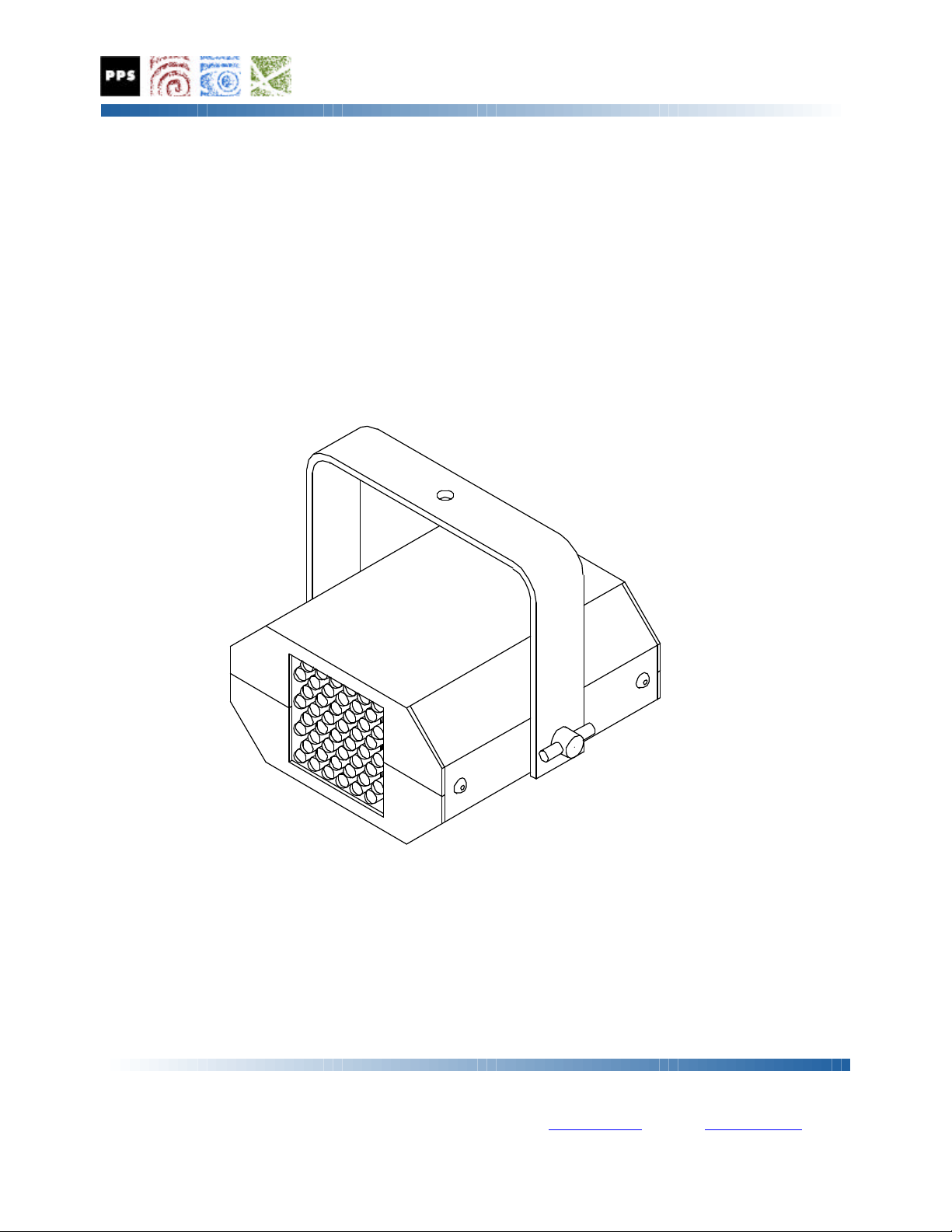
BL-48 DMX Ultraviolet Illuminator
The BL-48 Ultraviolet Illuminator is a state of the art lighting instrument based on an array of 48
Ultraviolet LED's and a computer micro-controller. This unit permits ultraviolet effects to be faded
or strobed under DMX control. These effects cannot be created with other types of UV
illumination. The LED UV devices do not require replacement, produce little or no heat, and are
available in a range of dispersion angles and UV or near-UV wavelengths. From one to four
channels of DMX-512 data controls UV intensity, strobe rate, or other parameters as determined by
the LED configuration, and the settings of internal mode jumpers. The unit may also be operated in
manual mode without DMX as a stand-alone fixture with preset intensity and strobe timing if
desired. Illuminators may be controlled by any DMX lighting system for professional displays, or
may be set up for independent operation at a preset intensity or strobe rate in stand-alone UV
lighting applications.
A range of UV LED options are now available for installation in the unit. For replacing existing
fluorescent or incandescent UV light sources, 395 nanometer UV LED's may be installed to
duplicate the deep blue-violet output common to those fixtures. For pure ultraviolet displays, 385
nanometer LEDs, which produce very little visible light may be selected. UV LED sources of
different types, or with different dispersion angles may be installed in the same fixture, with each
LED type then controlled independently through DMX, providing unprecedented flexibility in an
ultraviolet fixture. All LED emissions are long wavelength UV-A light, which is not considered a
skin or an eye hazard under normal conditions.
PRECISION PROJECTION SYSTEMS INCORPORATED
17508 STUDEBAKER ROAD, CERRITOS, CA 90703-3638
TELEPHONE: 562 865-8552 FACSIMILE: 562 924-7133

Precautions For Use
This device is intended for indoor use only, in dry locations free of excessive moisture or
condensation. The unit is intended for permanent installations in areas where the ambient
temperature is an average of 70 degrees Fahrenheit (F), and remains within the range of 40°F to
90°F at all times the unit is operational. Safe operation of the unit depends upon installation and
operation according to the following guidelines.
Rated Operating Voltage
The BL-48 unit is rated for operation from DC voltage sources
from 22 volts minimum to 24 volts maximum. Application of
power supply voltages in excess of the maximum rating may result
in damage to the unit electronics, and possible hazards including
fire and the risk of electrical shock.
Class III Product
The BL-48 unit provides protection meeting the requirements for Class
III electrical products. The unit is intended for operation with external
power supplies which comply with the SELV (Safety Extra Low
Voltage) requirements. Operation of the unit from power sources
which do not meet the SELV standard is not recommended, and may
result in an increased risk of electrical shock .
Suitable Mounting Surfaces
The BL-48 unit may be mounted to any suitable surface, including
those consisting of normally flammable materials such as wood or
plastic. Mounting may be accomplished using the five ¼-20 female
threaded attachment points along the back of the unit, or by drilling
holes as necessary in the flanges on either side of the unit, and then
securing it to the support structure with appropriate fasteners. The unit
may be mounted in any orientation.
Product Compliance
The BL-48 unit has been tested for compliance with the General and
Particular Standards for Luminaires, under EN 60598-1 (2004), and EN
60598-2-1 (1989), and also for compliance with the Electromagnetic
Compatibility (EMC) standards under EN 610000-6-3 (2001) and EN
610000-6-1 (2001), and are certified to comply with these standards.
F
24VoltsDC

CAUTION
This product contains Ultraviolet Light Emitting Diodes (LED’s). During operation, the
LED’s emit intense ultraviolet light. Precautions should be taken to avoid looking directly
into the UV output for prolonged periods with the unaided eye, viewing the UV output at close
range, or viewing through optical systems which enhance or concentrate the UV light. The
use of UV light protective glasses is recommended when the direct or reflected UV output
must be viewed for extended periods, at close range, or through optics.
DO NOT VIEW DIRECTLY WITH
OPTICAL INSTRUMENTS.
LED RADIATION
CLASS 1M LED PRODUCT
Controls and Connections
The rear panel of the unit includes a power input jack for a UL approved Class II 24 volt DC power
source, a red LED power indicator, and three rotary selector switches to choose the base DMX
address for the device. A slide switch to the left of the address switches can be set to provide a
resistive termination to the DMX data lines if the unit is the last device in the DMX data string. A
green LED DMX sync indicator is located to the left of the termination switch to provide a positive
indication of DMX data reception, and to confirm the mode setting of the unit on power up. The
DMX input and output connections are located on the lower half of the unit, to the left of the power
input socket.
Control Panel Connections

CAUTION
Connection of the unit to AC power sources, or to alternative power supplies other than the
universal input DC power pack provided with the unit may result in damage to the unit. Do
not attempt to operate the unit if you are unsure of the rating of the AC power source, or of
the voltage and polarity of any alternative DC power supply. Connections made to the DMX
Input and Output terminals must conform to the US-ITT DMX-512 standard to insure proper
operation of the unit. Any damage resulting from accidental application of incorrect power
supply or DMX signal voltages will not be covered by the system warranty.
Basic Operation
The unit may be operated from any AC power source from 100 to 240 volts AC, 50 or 60 Hz. The
universal voltage AC adapter provided with the unit will convert any AC power source within this
range to the 24 volts DC at .5 ampere maximum required by the unit. The unit is ready for
operation once the AC adapter is plugged into a suitable power source, and the DC output power
from the adapter is applied to the unit.
The LED power indicator on the rear panel will illuminate in green when the unit is on. When
power is first applied, the green DMX Sync indicator will blink from 1 to 4 times to indicate which
internal mode setting is selected. The internal processor will then read the address information
selected on the three DMX address switches, and will respond to appropriate DMX commands, or
to manual operation instructions as established by those switch settings and the internal mode
selected. After the start sequence is complete, the DMX Sync indicator will illuminate steadily in
green when valid DMX data is being received, and will not illuminate, or will flash intermittantly if
DMX data is absent or unstable.
Default Settings
Unless otherwise specified, all units are shipped with factory default mode and DMX address
settings. The default factory mode is Mode 1, single channel mode, where one DMX channel will
control the intensity of the UV emission from the unit. The default DMX address setting is to a
base address of 001.
The default setting of Mode 1 will allow access to the manual mode functions, which allow the unit
to be operated or evaluated without the need for a DMX signal source. Manual mode operation is
described more completely in a later section of this manual.
Base DMX Address Settings
The three rotary address switches are set to select the base DMX address for the unit. The address
switches should be preset to the desired base DMX address before the unit is powered up, as the
address settings are read during the power up sequence. If it is necessary to change the DMX
address for the unit, the address settings may be changed at any time, but the unit will not read or
respond to the new channel assignment until power is removed, and restored once again.

DMX Channel Useage and Allocation
Once the base DMX address is read, the unit will respond to changes in the DMX data for the
selected channel or channels depending upon the selected operational mode. From 1 to 4 DMX data
channels may be occupied by each unit depending on the internal mode setting. For all multi-
channel modes, the additional DMX channels occupied are sequentially higher than the base DMX
address selected by the selector switches. For example, a unit operating in Mode 2, which uses two
DMX channels, and set to a base DMX address of 100 would occupy and respond to information on
DMX channels 100 and 101. A unit set to Mode 4, which uses four DMX channels, and a base
DMX address of 200 would occupy and respond to information on DMX channels 200, 201, 202,
and 203.
DMX Data Connection
Once the base DMX address setting is complete, the unit may be connected to a DMX data source.
The green “Sync” indicator will illuminate steadily if valid DMX data is being received by the unit.
In normal operation, the unit will respond to changes in the DMX data for the selected channel or
channels by increasing or decreasing the intensity of each LED emitter, or varying the motor speed
in direct response to the DMX channel control levels. When normal DMX data is being received,
the unit will retain the last valid data for about 5 seconds after the DMX data is removed. This data
retention allows the unit to tolerate minor interruptions in the DMX data stream caused by poor
connections or brief “dropouts”. After this interval, the unit will default to the normal “no DMX
data” state, with all output channels inactive. Normal operation will resume immediately when the
normal data stream is restored.
DMX Troubleshooting
If the “Sync” indicator is not steadily illuminated when DMX data is connected, then there is either
a problem with the DMX data or cables, or an internal problem with the unit. If the unit does not
operate, and the “Sync” indicator flashes at a regular interval, the DMX address is set to an invalid
range, either to zero, or to a number higher than 512, which is the highest base address setting
which will allow control of the fixture in single channel mode. If the “Sync” indicator is erratic,
then the DMX data connection is either intermittent due to a poor electrical connection, or the DMX
data is dropping out, which can be caused by poor connections, poor quality cables, long data runs,
or poor signal quality in general. Test the unit with different cables, or in a different location closer
to the DMX data source to determine what or where the problem is.
Operational Mode Settings
The BL-48 unit may be operated in any one of four modes as selected by internal programming
jumpers. Power must be removed from the unit before opening the cover to change the mode
jumper settings. Once the unit is inactive, the upper housing of the unit may be opened by
removing the four screws along the sides. Once the screws are removed, the top cover may be
opened to gain access to the internal circuit board with the jumpers.

Operational Modes
The mode selection corresponds with the number of consecutive DMX channels used in each mode,
beginning from the base DMX address selected by the address switches. The DMX channel
function and operation of the unit in each mode is listed in the following table.
Mode Functions Manual Channels Ch. 1 Ch. 2 Ch. 3 Ch. 4
1 Intensity
Only Yes 1 Master
Intensity Unused Unused Unused
2 Intensity &
Strobe No 2 Master
Intensity Strobe
Rate Unused Unused
3 3 Channel No 3 Bank 1
Intensity Bank 2
Intensity Bank 3
Intensity Unused
4 3 Channel
+Master No 4 Master
Intensity Bank 1
Intensity Bank 2
Intensity Bank 3
Intensity
Mode Selection
The Mode Select jumpers are J7 and J8 located near the right edge of the main circuit board
between the large regulator IC and the power input socket. Move the shorting jumpers as indicated
in the diagram below to change the operating mode. Refer to the parts layout drawing which
appears later in this manual for further illustrations of the jumper location if necessary.
Once the desired mode settings are in place, the top cover of the unit should be replaced, and the
screws reinstalled before applying power to the unit. Operation of the unit in the desired mode may
be confirmed by observing the DMX Sync indicator lamp, which will blink from 1 to 4 times when
power is first applied to the unit to indicate which mode is currently selected.

Mode 1 Operation: Master Intensity on 1 DMX Channel
Mode 1 is the simplest operational mode, using only a single DMX channel, corresponding to the
base address selected by the three address switches. The data on that DMX channel will control the
intensity of the output from the unit, with a zero level producing no output, and a maximum level of
255 producing maximum output from the unit. Manual mode operation, as described later in this
document, is only available when the unit is set to Mode 1.
Mode 2 Operation: Master Intensity plus Strobe on 2 DMX Channels
Mode 2 allows control of both Intensity and Strobe rate, and uses two DMX channels beginning
with the base address selected by the address switches. The data on the first DMX channel will
control the intensity of the output from the unit, with a zero level producing no output, and a
maximum level of 255 producing maximum output from the unit. The data level on the second
DMX channel will control the flash or strobe rate of the unit, with a zero level producing a one
second flash every other second, with a maximum flash rate of around 30 flashes per second at a
data level of approximately 245. Data levels from 245 to the maximum of 255 will result in
continuous operation. Manual operation, as described later, is not available in Mode 2.
Mode 3 Operation: 3 Bank Intensity on 3 DMX Channels
Mode 3 allows individual control of Intensity for each of the three banks of 16 LED devices
installed in the unit. This mode uses three DMX channels beginning with the base address selected
by the address switches. The data on the first DMX channel will control the intensity of the LED
devices in Bank 1, with a zero level producing no output, and a maximum level of 255 producing
maximum output. The data levels on the second and third DMX channels will control the output of
the LED devices in Banks 2 and 3 in a similar manner. This mode is most commonly used with a
mixture of LED dispersions, wavelengths, or with banks of UV and White LED’s. Manual
operation, as described later, is not available in Mode 3.
Mode 4 Operation: Master Intensity plus 3 Bank Intensity on 4 DMX Channels
Mode 4 allows individual control of Intensity for each of the three banks of LED devices installed
in the unit, plus a master level control. This mode uses four DMX channels beginning with the base
address selected by the address switches. The data on the first DMX channel will control the
intensity of all LED devices in all banks, with a zero level producing no output, and a maximum
level of 255 producing maximum output, up to the levels set by the individual bank controls. The
data levels on the second, third, and fourth DMX channels will control the output of the LED
devices in Banks 1, 2, and 3 in a similar manner. This mode is most commonly used with a mixture
of LED dispersions, wavelengths, or with mixed banks of UV and White LED’s. Manual
operation, as described later, is not available in Mode 4.

Manual Mode Displays
The manual mode displays are intended to provide the unit with a reasonable capability for
demonstrating the properties of the unit, and are also useful for testing This capability may also be
sufficient to complete simple effect installations where the cost or complexity of DMX controls are
not necessary, but the benefits of a compact and very low maintenance UV source would be
attractive. For those installations where the manual mode capacity of the unit are not precise or
flexible enough, the use of the DMX control features should allow the unit to perform exactly as
required.
Manual Mode Operation
Manual Mode operation is available only when the internal Mode jumpers in the unit are set to
Mode 1, and the DMX address switches on the unit are set to addresses 600 and higher, which are
beyond the normal range of the DMX-512 standard of 512 channels. The address switch settings in
the range of from 600 to 699 and from 700 to 799 correspond to distinct manual mode functions as
described in the following table:
Manual Mode Minimum Maximum Minimum Effect Maximum Effect
Intensity 600 699 0% 100%
Strobe 700 799 .5 Hz. 30 Hz.
Manual Display Programming
Operation of the unit in Manual Mode is controlled by the settings of the DMX address switches.
The output of the unit may be adjusted using the address switch settings to obtain a wide range of
intensity levels and strobe rates. Once established, manual mode settings are retained when power
is removed from the unit, and will be restored when power is reapplied provided that no changes are
made to the address switch settings. The manual settings may be altered by adjusting the settings at
any time. The unit will resume normal DMX operations when the address switches are set to a
value of 512 or less.
Manual Mode Intensity Control
When the base address switches are set to a range of 600 to 699 when power is first applied to the
unit, the unit will produce UV output from 0 to 100 percent intensity, with no output at a setting of
600, and maximum output at a setting of 699. Output within this range is continuous, and is not
affected by any other setting.
Manual Mode Strobe Rate Control
When the base address switches are set to a range of 700 to 799 when power is first applied to the
unit, the unit will produce strobed UV output at 100 percent intensity, with a minimum rate of .1
Hz. (5 seconds on, 5 seconds off) at a setting of 700, and a maximum rate of approximately 30 Hz.
at a setting of 799. Control settings above this level will result in continuous output.
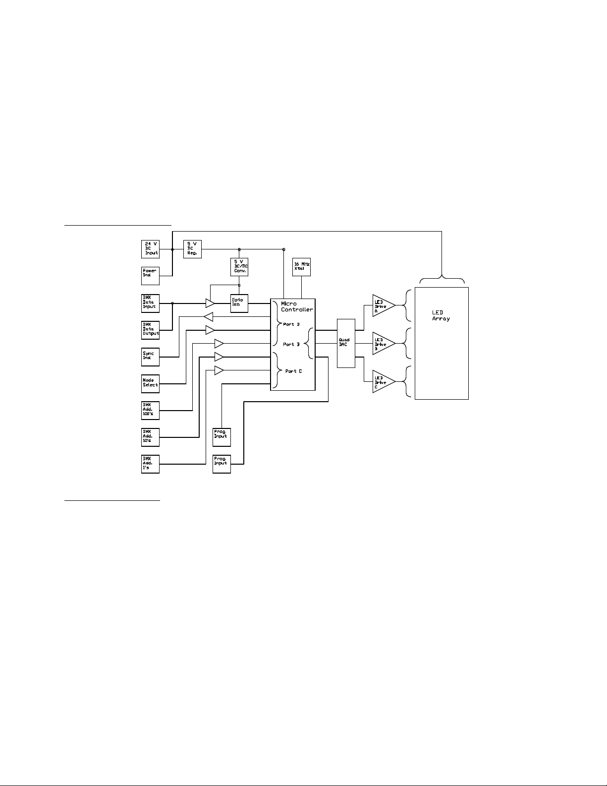
Circuit Description
The BL-48 Illuminator circuitry is most easily described as six sections, which are the power
supply, the microcontroller, the DMX interface section, the address and mode selection section, the
DAC or PWM output section, and the LED drivers and array. The microcontroller is the key
element in the circuit, as the data ports on the device are assigned to all key circuit and interface
functions. The microcontroller responds to settings of the mode and address control switches, reads
incoming DMX data with the proper address information, and generates the output data which
controls the LED drivers. Each circuit section is explained in further detail below.
Circuit Block Diagram
Theory of Operation
Upon power up, the microcontroller sets the configuration of all internal registers and variables
according to firmware programming, then reads the settings of the internal mode jumpers to
determine the general display configuration. Once these settings are established, the controller then
reads the settings of the DMX address switches, and goes into either a manual display mode if the
address settings are 600 or higher, or a DMX controlled mode if the address settings are in the range
of from 1 to 512. If no DMX data is available, the unit enters a “Standby” state, prepared to
respond to valid DMX data input. The microcontroller monitors the DMX control lines, and awaits
a signal to initiate a display. Upon receipt of a suitable signals, the controller then sets the intensity
or other display variables to the to the required levels established by the DMX data. The display is
maintained at the last valid level for a preset interval of about 5 seconds if DMX data is lost or
interrupted. If no DMX data is received after this interval, the controller then returns to the normal
standby state, and continues to monitor the inputs for additional DMX control signals.

Power Supply.
The illuminator is powered by an external DC power pack, or wall type transformer at a voltage of
24 volts DC, and a current of 350 milliamperes minimum. Suitable power sources are available
with approvals from UL and other electrical safety agencies, and in several input voltage ranges.
Power is applied to the illuminator unit through the 2.1 millimeter center positive DC plug J1 on the
rear panel of the unit. Power applied to unit passes through a self resetting current limiter, a
polarity protection diode, and a transient surge absorber before it is applied to the 5 volt regulator
IC Q3, which reduces the input voltage to the 5 volt level required by the microprocessor and other
logic circuitry. The higher unregulated voltage from the external power supply is applied to the
power / sync indicator LED, and to the LED array, as the extra voltage is needed to drive the series
connected ultraviolet LED’s used in the array. A separate 5 volt DC to DC converter is used to
power the DMX input section. This separate power supply allows the electrical isolation of the
DMX input and output lines from the remaining circuits in the unit.
Microcontroller
The illuminator is based on an Atmel ATMEGA8 microcontroller U2, which operates all critical
illuminator functions. The microcontroller uses an external 16 megahertz clock oscillator X1 for
timing control, and is internally protected against transient voltage conditions. The processor
operates from permanent firmware EPROM programming which controls all functions of the
illuminator. This programming is performed during manufacturing, and may not be re-written by
the user. The microcontroller has three 8 bit input / output ports, which may be programmed as
needed for each particular application. These ports are commonly identified by letter designations,
B, C, and D. In the BL-48 illuminator, the B port is used output data to the LED driver circuitry,
and for device programming, the C port is used for device programming and to read DMX address
settings, and the D port is to read address and mode settings, and for DMX input and sync
indication.
DMX Interface Circuits
The DMX data stream is applied to the BL-48 unit on the 5 pin male XLR connector J2, and passed
directly through to the 5 pin female XLR connector J3. DMX data is buffered by the IC U5, and the
opto-isolator OP1 before it is applied to the RXD terminal of the microcontroller on pin 30 (PD0).
The microcontroller processes the incoming DMX data, and indicates proper data reception by
outputting a sync indication on pin 11 (PD7) to the LED driver Q1 and the power / sync indicator
LED
Address / Mode Selection Circuit
The three DMX address switches S1,2 and 3 are connected directly to microcontroller inputs on
pins 23 through 28, (PC0-5), on pins 31,32, 1, and 2 (PD1-4), and on pins 19 and 22 (ADC6,7).
These pins to provide DMX address information to the microcontroller. Other inputs on pins 9 and
10 (PD5,6) are used to select the general operating mode of the unit. The remaining input
connections on pins 14-17, and 29 (PB2-5, PC6) are used for device programming.

DAC / PWM Output Circuit
The digital output data from the microcontroller can be processed in either of two ways. The first
uses a serial data output on pin 12 (PB0) which is applied to the input of the serial input Quad
“digital to analog converter” or DAC IC U4 on pin 9 of that device. Analog output voltage from
three of the four DAC channels is output on pins 11, 12, and 15 of U4, and applied to the inputs of
the LED driver array. The second output method uses “pulse width modulation” or PWM data from
the processor on pins 13, 14, and 15 (PB1, 2, and 3) which are applied to the quad op amp IC U3 on
pins 12, 10, and 3, respectively. The filtered output from these op amps is then applied to the inputs
of the LED driver array. Only one of these two output methods is installed on the circuit board,
with the components for the alternative method omitted.
LED Array and Driver Circuit
The LED array is a separate circuit board from the microcontroller, and attaches to the CPU board
through the power and signal interface plugs P1, and P2. The LED display board is the simplest
portion of the circuit, as it consists of 3 identical circuits, each containing 16 LED elements, an op
amp, and a driver transistor. In each section, the LED emitters D1-D16, D17-32, and D33-48 are
wired as an 4 column by 4 row series-parallel array. Each array is connected to the 24 volt DC
supply, with the op amps U1 and U2, and the current regulating transistors Q1, 2, and 3 responding
to control voltages from the microcontroller to determine the current flow through each portion of
the array. Depending on the settings of the microcontroller, each of the three section may be
controlled independently ar will act as a single unit.
Service Access
The active electronics of the BL-48 illuminator are mounted on two circuit boards inside the main
housing of the unit. These may be accessed by removing the four screws along the sides of the unit
to open the main housing. The unit may be operated normally with the cover removed. Provided
that the unit is operated with a suitable power supply, there are no hazardous voltages present in the
interior of the unit
Basic Troubleshooting
With the exception of the microcontroller, the circuitry used in the illuminator is quite simple, and
troubleshooting is made quite easy by using the available power and data sync indicators and
manual operating modes, and by observing the LED array for any erroneous output.
In the event that the illuminator fails to produce a normal output, first check for good AC power to
the power pack, and for the LED power indicator on the rear panel. If the LED indicator is not
active, then the external power pack or supply is not powered or is defective.
If the power LED is lit, apply DMX data to the unit, and observe for illumination of the “Sync”
indicator adjacent to the Power indicator. If the Sync LED is lit, the unit is receiving normal DMX
data, and should respond to data within the proper address range. If the unit does not respond,
check the settings of the DMX address switches for correct settings.

Remember that the unit loads DMX address data only when powered up, and power must be
removed and restored before the unit will respond to a change in the DMX address or mode selector
settings. If the settings are correct, but no display is observed, then the DMX control signal may be
intermittant or low quality, or the unit may have an internal problem with the DMX address or
mode selection circuitry, or with the LED display or driver circuits. .
To check the basic function of the unit, remove power and DMX connections and set the unit to
manual mode by setting the DMX address switches to 699. Reapply power to the unit, and observe
the display. If a normal display is observed, then the LED and driver circuits are fully functional,
but the DMX control input signal is absent, or is being ignored by the illuminator. Check the
setting of the mode selector and address switches for proper choice of display mode and DMX
address range. Failure of the unit to respond to a known good DMX data signal when set to the
proper mode and address range indicate a problem with the internal circuitry.
Other PPS Lighting Equipment manuals

Popular Lighting Equipment manuals by other brands


EOS
EOS LED FLEX 947317 installation manual

Public Safety Equipment
Public Safety Equipment CODE 3 FM 9000 Installation & operation manual

Home Zone Security
Home Zone Security ELI0983V installation instructions

KOZii
KOZii KRFDE470STACCT instruction manual

VelLight
VelLight LEDS12CWW user manual

Martin
Martin MAC 101 Series Brochure & specs