Showline SL PUNCHLITE 220 User manual

SL PUNCHLITE 220
SL PUNCHLITE 220 Installation & User’s Manual
Version as of: 24th Oct, 2014 Rev1.0
2014 Philips Group. All rights reserved.
Showline Offices
Showline - Dallas
10911 Petal Street
Dallas, TX 75238
Tel: 214-647-7880
Fax: 214-647-8030
Showline - Europe
Marssteden 152
Enschede 7547 TD
The Netherlands
Tel: +31 53 4500424
Fax: +31 53 4500425
Showline - Auckland
19-21 Kawana Street
Northcote, Auckland 0627
New Zealand
Tel: +64 9 481 0100
Fax: +64 9 481 0101
Showline - Asia
Unit C, 14/F, Roxy Industrial Centre
No. 41-49 Kwai Cheong Road
Kwai Chung, N.T., Hong Kong
Tel: +852 2796 9786
Fax: +852 2798 6545
Website:
www.philips.com/showline
The material in this manual is for information purposes only and is subject to change without notice. Showline assumes
no responsiblitity for any errors or omissions which may appear in this manual. For comments and suggestions regarding
corrections and/or updates to this manual, please visit the Showline website at or contact yourwww.philips.com/showline
nearest Showline office.
Note: Information contained in this document may not be duplicated in full or in part by any person without prior written
approval of Showline. Its sole purpose is to provide the user with conceptual information on the equipment mentioned. The use of
this document for all other purposes is specifically prohibited.
Document Number: SL PUNCHLITE 220 User’s Manual
Additional Resources for DMX512
For more information on installing DMX512 control systems, the following publication is available for purchase
from the United States Institute for Theatre Technology (USITT), "Recommended Practice for DMX512: A Guide
for Users and Installers, 2nd edition" (ISBN: 9780955703522). USITT Contact Information:
USITT
315 South Crouse Avenue, Suite 200
Syracuse, NY 13210-1844
Phone: 1.800.938.7488 or 1.315.463.6463
www.usitt.org
Showline Limited Two-Year Warranty
Showline offers a two-year limited warranty of its luminaires against defects in materials or workmanship from the
date of delivery. A copy of the Showline two-year limited warranty containing specific terms and conditions can
be obtained by contacting your local Showline office.
Warnings and Notices
When using electrical equipment, basic safety precautions should always be followed including the following:
READ AND FOLLOW ALL SAFETY INSTRUCTIONS.
Do not mount near gas or electric heaters.
Equipment should be mounted in locations and at heights where it will not readily be subject
to tampering by unauthorized personnel.
The use of accessory equipment not recommended by the manufacturer may cause an unsafe
condition.
Do not use this equipment for other than intended use.
Refer service to qualified personnel.
WARNING: You must have access to a mains circuit breaker or other power disconnect device
before installing any wiring. BE sure that power is disconnected by removing fuses or turning the
mains circuit breaker off before installation. Installing the device with power on may expose you
to dangerous voltages and damage the device. A qualified electrician must perform this installation.
WARNING: Refer to National Electrical Code and local codes for cable specifications.
Failure to use proper cable can result in damage to equipment or danger to personnel.
WARNING: This equipment is intended for installation in accordance with the Nation Electric
Code and local regulations. It is also intended for installation in indoor applications only. Before
any electrical work is performed, disconnect power at the circuit breaker or remove the fuse to
avoid shock or damage to the control. It is recommended that a qualified electrician perform this
installation.
Installation & User’s ManualSL PUNCHLITE 220
IMPORTANT INOFRMATION

TABLE OF CONTENTS
Showline Offices Inside Front Cover
IMPORTANT INFORMATION
Warnings and Notices
Additional Resources for DMX512
Showline Limited Two-Year Warranty
TABLE OF CONTENTS
PREFACE
About this Manual
Included Items
SL PUNCHLITE 220 OVERVIEW
SL PUNCHLITE 220 Components
INSTALLATION AND SET UP
Connecting Power
Connecting the SL PUNCHLITE 220 to AC Power
Truss / Hanging Applications
Floor Mounting
Connecting to the DMX512 Network
Mounting Luminaire
OPERATION AND PROGRAMMING
LCD Display and Menu System
LCD Display and Menu System Operation
SL PUNCHLITE 220 Menu Tree
Quick Selection Buttons
Edit a Preset Button
Edit a Chase Button
DMX Address Button
Dimming Curve Selection
Master / Slave Operational Mode
DMX CONTROL
RDM PARAMETER IDs
Simple 8-Bit Mode
Simple 8-Bit Group Mode
RGBW 8-Bit Mode
RGBW 8-Bit Group Mode
RGBW 16-Bit Mode
RGBW 16-Bit Group Mode
HSIC Mode
HSIC Group Mode
DMX Timing Channel Detail
SL PUNCHLITE 220 DMX Mapping
SL PUNCHLITE 220 RDM Parameter IDs
CLEANING AND CARE
Special Cleaning and Care Instructions
Front Lens Cleaning
Service and Maintenance
TECHNICAL SPECIFICATIONS
Operational Specifications
Luminaire Dimensions
Table of contents
2
1
1
1
3
3
4
6
6
8
8
7
8
9
10
11
13
13
13
13
14
15
16
17
18
22
23
27
28
29
30
16
36
39
39
39
40
41

PREFACE
1. About this Manual
The document provides installation and operation instructions for the following products:
SL PUNCHLITE 220 Luminaire
Please read all instructions before installing or using this product. Retain this manual for future reference.
Additional product information and descriptions may be found on the product specification sheet.
Note: The SL PUNCHLITE 220 has a universal voltage range of 100 to 240 VAC (auto-ranging).
2. Included Items
Each SL PUNCHLITE 220 luminaire includes the following items:
SL PUNCHLITE 220
SL PUNCHLITE 220 Luminaire
Quick Start Guide
3
About this Manual
Installation & User’s ManualSL PUNCHLITE 220
SL PUNCHLITE 220 Overview
4
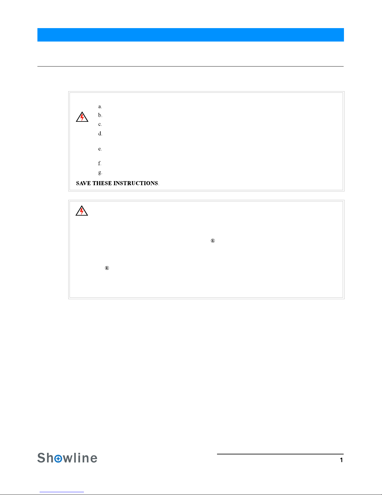
1.SL PUNCHLITE 220 COMPONENTS
Common Luminaire Components
LCD Display / Menu System
Figure 2: LCD Display & Menu System
Note: For Menu operation and programming details, refer to "LCD Display and Menu System" on page 9.
Front of Unit
Rear of Unit
DMX512 / RDM Input DMX512 / RDM Output
AC Input
High Power LEDs
Yoke
AC Output
SL PUNCHLITE 220
Home (menu settings)
Edit a Preset Edit a Chase
DMX512 Addressing
Return to Main Screen
LEFT Arrow Button UP Arrow Button
CHECK MARK (Accept) Button
DOWN Arrow Button
RIGHT Arrow Button
LCD Display
NOTE: Menu rotates with orientation of
luminaire and menu buttons are always in
the same position (with rotation of menu)
To rotate menu 180 degrees from current orientation,
press and hold the two center buttons for 2 seconds.
LCD Display / Menu System
SL PUNCHLITE 220 OVERVIEW
Safety Cable
Anchor Point
Figure 1: SL PUNCHLITE 220 Common Components
Installation & User’s Manual SL PUNCHLITE 220
Tilt Knob

5
Installation and Set Up
INSTALLATION AND SET UP
1.Power Requirements
The SL PU NCHLITE 220 operates on AC input voltages from 100 to 240 VAC.
WARNING! The SL PUNCHLITE 220 does not have an ON/OFF switch. Always disconnect power input cable to
completely remove power from the luminaire when not in use.
AC Power Operation
When connected to an AC source, the unit operates on 100 to 240 volts AC (+/- 10%, auto-ranging). The luminaire
contains an auto-ranging power supply. Each luminaire can draw up to 230 Watts.
WARNING! Maximum amount of fixtures that may be daisy-chained is (A) 6 units 100 ~ 120VAC or (B) 15 units
230 ~ 240VAC (15 Amps).
Note: For wiring of AC input connector, refer to "Connecting SL PUNCHLITE 220 to AC Power" on page 6.
2.Connecting Power
Units can be powered in one of two ways:
Direct connection to an AC power source using an AC input cable. For wiring of the AC input connector, refer to
Connection from the AC output of another SL PUNCHLI TE 220. When using this method, it is very important not
to connect any other type of equipment device.
WARNING! Only connect other SL PUNCHLITE 220 to the AC Output (Thru) connector of a SL PUNCHLITE 220.
Installation & User’s ManualSL PUNCHLITE 220
Table 1: SL PUNCHLITE 220Voltage (VAC) vs. Current*
"Connecting SL PUNCHLITE 220 to AC Power" on page 6.
100 180 1.27
2.30
110 190 1.21
2.1
160 240 0.95
1.43
150 230 1.01.53
140 220 1.04
1.64
130 210 1.09
1.77
120 200 1.15
1.91
170 1.35
Voltage (AC) Voltage (AC)
Total Current (A) Total Current (A)

Connecting SL PUNCHLITE 220 to AC Power
6
Connecting SL PUNCHLITE 220 to AC Power
Table 2 describes how to connect power to your SL PUNCHLITE 220. Field wiring of the SL PUNCHLITE 220
LED Luminaire is straight-forward. A total of 3 wires/conductors need to be brought to the unit. The following
wiring scheme is required:
Figure 3: SL PUNCHLITE 220 AC Input & Output Connections
Luminaire
Brown Main/Line(100 to 240VAC)
Blue Neutral
Green/Yellow Ground (Earth)
Table 2: SL PUNCHLITE 220AC Input Connections
AC Input AC Output
Installation & User’s Manual
Wire Color Purpose
SL PUNCHLITE 220

Connecting to the DMX512 Network 7
3.Connecting to the DMX512 Network
Basic DMX512 installation consists of connecting multiple SL PUNCHLITE 220 units together (up to 15 luminaires) in
"daisy-chain" fashion. A cable runs from the control console (or DMX512 control source) to the DMX connector on
the first SL PUNCHLITE 220. Another cable runs from the other DMX connector on the first unit to a DMX
connector on the next SL PUNCHLITE 220 (or DMX512 device to be controlled).
Figure 4: SL PUNCHLITE 220 DMX512 Input / Output Connections
Note: For more information on DMX512 networking and systems, refer to "Additional Resources for DMX512" on
page 1 "DMX CONTROL" on page 16. For SL PUNCHLITE 220 DMX Mapping, refer to .
Figure 5: SL PUNCHLITE 220- DMX512 Connections
DMX512 / RDM DMX512 / RDM
Luminaire
DMX512
DMX512 (out from first
to second luminaire)
DMX512 (out to the next
(from console or
control device)
Input Connector THRU Connector
DMX512 Conections
DMX512 Signal
Common (Drain)
DMX512-
DMX512+
XLR Pin
Note: Remaining pins on each connector are not used.
1
2
3
Installation & User’s ManualSL PUNCHLITE 220
luminaire or DMX512 controlled
device)

Mounting Luminaire
8
4.Mounting Luminaire
Truss / Hanging Applications
The SL PUNCHLITE 220 is provided with the ability to hang via truss hooks, clamps, etc. (sold separately). Simply
attach hook, clamp, etc. to the SL PUNCHLITE 220 yoke in the provided M10 holes. It is recommended (and may be
required by local and national safety codes) to use and install a safety cable (sold separately) as illustrated in Figure 6.
When hanging the fixture, be sure to leave enough space around the luminaire to allow proper, uninterrupted airflow for
cooling and movement. Refer to "Luminaire Dimensions" on page 36 for spacing (dimensional) requirements.
Note: Mounting hooks, clamps, safety cables, etc. are sold separately or by others. For mounting accessories
available for this product, refer to "Accessories" on page 3.
Figure 6: Mounting the Fixture - Hanging Applications
Floor Mounting
The SL PUNCHLITE 220 is designed to sit directly on its split yoke in a floor installation application. When used in this
type of application, be sure to leave enough space around the luminaire to allow proper, uninterrupted airflow for
cooling and movement.
Installation & User’s Manual
Safety Cable Anchor Point
Truss Hook or Clamp
(sold separately)
SL PUNCHLITE 220

OPERATION AND PROGRAMMING 9
OPERATION AND PROGRAMMING
1.LCD Display and Menu System
SL PUNCHLITE 220
The SL PUNCHLITE 220’s LCD Display and Menu System provides local control for accessing
the following fixture’s settings:
Presets (Standard and User Defined)
Color Filter
Effects (Chases - preloaded and user defined)
Strobe / Timing
Settings
Lock Fixture (to prevent changes)
Password
Status
Note: If there are multiple luminaires in a system, changes would need to be made at each LCD Menu as desired. For
SL PUNCHLITE 220 menu structure, see . "SL PUNCHLITE 220 Menu Tree" on page 11
Upon power up, the LCD will display the main screen showing the product type/name. If DMX is enabled, the
programmed address will appear after power up.
Figure 7: LCD Display and Menu System
SL PUNCHLITE 220
Home (menu settings)
Edit a Preset Edit a Chase
DMX512 Addressing
Return to Main Screen
LEFT Arrow Button UP Arrow Button
OK (Check Mark) Button
DOWN Arrow Button
RIGHT Arrow Button
LCD Display
NOTE: Menu rotates with orientation of Luminaire and
menu buttons are always in the same position (with
rotation of menu)
To rotate menu 180 degrees manually from current
orientation, press and hold the two center buttons for 2
seconds.
Installation & User’s ManualSL PUNCHLITE 220

LCD Display and Menu System Operation
10
2.LCD Display and Menu System Operation
The LCD Display Menu system consists of several categories. Use the Menu Buttons to access and make changes to
the menu items. When the desired menu item is reached, press the desired Menu Button to display the menu options
and to navigate and configure the menu options as required.
To navigate and access menu settings/selections:
Step 1.Make sure unit is powered and turned on.
Step 2.Press the desired button (as shown in Figure 8) to access menu categories.
Step 3.Use UP | DOWN | LEFT | RIGHT arrow buttons to navigate through the various options and settings.
Step 4.Make changes as desired.
Press CHECK MARK (OK) button to accept changes.
Figure 8: LCD Display and Menu System
SL PUNCHLITE 220
Home (menu settings)
Edit a Preset Edit a Chase
DMX512 Addressing
Return to Main Screen
LEFT Arrow Button UP Arrow Button
OK (Check Mark) Button
DOWN Arrow Button
RIGHT Arrow Button
LCD Display
NOTE: Menu rotates with orientation of Luminaire and
menu buttons are always in the same position (with
rotation of menu)
To rotate menu 180 degrees manually from current
orientation, press and hold the two center buttons for 2
seconds.
Installation & User’s Manual SL PUNCHLITE 220

SL PUNCHLITE 220 Menu Tree 11
Continued on next page
3. SL PUNCHLITE 220 Menu Tree
Figure 9: SL PUNCHLITE 220 Menu Tree(Part 1)
Installation & User’s ManualSL PUNCHLITE 220
MAIN MENU
Strobe/Timing
Preset
Effects
Color Filter Color Filter (0 thru 43)
Master Intensity 0-100%
Strobe xxxx
Duration
Intensity Timing 0.2 S-60 Min
Preset X(0 thru 31)
Chase
Speed 0.2 S-30 Min
1 thru 10
RGB Mode
Pixel 1-3_CCT
Pixel 1-3_Intensity
DMX Through
Master Intensity 0-100%
DMX Through
Capture DMX
HSIC Mode Master Intensity 0-100%
Pixel 1-3_Saturation 0-100%
On/Off
Capture DMX
Zoom 0-255
0-100%Master Intensity
Pixel 1-3_Hue 0-359 degree
Preset X/Color Filter X RGB Mode
0-100%
Pixel 1-3_White 0-100%
0-100%Pixel 1-3_Green
0-100%Pixel 1-3_Red
Pixel 1-3_Blue
Pixel 1-3_Saturation 0-100%
HSIC Mode
Pixel 1-3_CCT 2700K-6500K
Zoom
Pixel 1-3_White
Capture DMX
0-100%
2700K-6500K
0-100%
0-100%
0-100%
0-100%
0-255
Master Intensity
Pixel 1-3_Red
Pixel 1-3_Green
On/Off
Capture DMX
New Step
Delete Step
Zoom 0-255
Edit Step x (1 thru 100)
Built-in Chase
Edit Chase x(1 thru 8)
Select Chase x(1 thru 8)User Chase
Master Intensity 0-100%
Zoom Timing 0.2 S-60 Min
0.2 S-60 Min
0--85
Color Timing
Pixel 1-3_Blue 0-100%
Zoom 0-255
DMX Through On/Off
Capture DMX Capture DMX
Zoom 0-255
Fade 0-100%
Zoom 0-255
On/Off
Capture DMX
0-100%
DMX Through
Capture DMX
Master Intensity
Pixel 1-3_Intensity 0-100%
Pixel 1-3_Hue 0-359 degree

SL PUNCHLITE 220 Menu Tree
12
Figure 10: SL PUNCHLITE 220 Menu Tree(Part 2)
Installation & User’s Manual
3333
0-100%
Red
Max Intensity 0-100%
xx Celsius degree
83 Celsius degree
86 Celsius degree
xx Celsius degree
Max_Value
HSIC Mode
0-100%
S-Curve
Power Up
Locked/Level 1-3 /disable
Password
Disable
Auto
OFF
1 or 3
0-100%
Other Information RDM UID 0X000000000000
0-100%
Warning Low
Warning High
Min_Value
Firmware Version Rev 0.0
xx Celsius degree
0-100%
Blue
NoLoad Factory
Preset & Chase
Protected NoFactory Default
Power-upGeneral
Security
Settings
Power-up Level
Enter PassPIN
Level 2 PIN
Level 1 PIN
****
Last Set
Status
Lock Fixture
Password
Flip DisplayDisplay
When no DMX
Yes(to lock Fixture)LOCK Are you sure?
Off Time
Pixel 1-3 LED
Current Level
Master Intensity
Mode
ON
LED Group
RGBW 8-bit Mode
1 to 512
Simple 8-bit Mode
Last Action
Hold
Off
Fan Control
Chase(1 thru 18)
Color Filter (1 thru 43)
Preset X(1 thru 32)
1111
2222
Incandescent
linear
Square
Master
Temperature
Enter Pass PIN Level 1-3
No
DMX
Address
DMX Enable
Temperature
Green
Language Select
Map
White
Movement Zoom 0-255
Dimming Curve
(DMX 8Bit)
Enable
Yes
PL-Curve
Slave
Normal
RGBW 16-bit Mode
DIM Response
OFFCalibration
Level 3 PIN
English
On/30S/1Min/ 5Min/10Min
Auto
Yes
No
Continued from
previous page
SL PUNCHLITE 220

Quick Selection Buttons 13
4.Quick Selection Buttons
When in Manual Mode, the SL PUNCHLITE 220's features can be accessed via the on-board LCD menu system or
via three quick select buttons:
Edit a Preset Button
Edit a Chase Button
DMX Address Button
Edit a Preset Button
To edit and save a preset:
Step 1.Press Edit a Preset button. Current preset will be shown.
Step 2.Use LEFT and RIGHT arrow buttons to scroll through all presets.
Step 3.Once at desired preset, use U P and DOWN arrows to access
(highlight) preset parameters. Once in desired parameter, use LEFT
and RIGHT arrow buttons to adjust parameter value as desired.
Step 4.Once all values are adjusted as desired, press OK (Check Mark) button.
Step 5.Save preset menu option will appear. Use LEFT and RIGHT arrow buttons to select preset number.
Step 6.If saving preset, press OK (Check Mark) button. C o nfirm choice.
Step 7.Preset is now saved.
Edit a Chase Button
To edit and save a chase:
Step 1.Press Edit a Chase button. Current chase will be shown.
Step 2.Use LEFT and RIGHT arrow buttons to scroll through all chases
(Built In and User Chases).
Note: For Built In Chases, only the Speed and Fade parameters may be
changed and saved. For User Chases, Chase Number, Total Steps, Speed, and
Fade Parameters may be changed and saved.
Step 3.Once at desired chase, use UP a n d DOWN arrows to access (highlight ) chase parameters. Once in desired
parameter, use LEFT and RIGHT arrow buttons to adjust parameter value as desired.
Step 4.Once all values are adjusted as desired, press OK(Check Mark) button.
Step 5.Save chase menu option will appear. Use LEFT a n d RIGHT arrow buttons to select chase number.
Step 6.If saving chase, press OK (Check Mark) button. Confirm choice.
Step 7.Chase is now saved.
DMX Address Button
To edit and save a DMX address:
Step 1.Press DMX Address button. Current DMX Address will be shown.
Step 2.Press OK (Check Mark) button to highlight a digit in the DMX
address.
Step 3.Use LEFT and RIGHT arrow buttons to scroll through all digits.
Step 4.Once at desired digit, use UP and DOWN arrows to change
highlighted digit. Once digit is set, use LEFT and RIGHT arrow buttons to set other digits in DMX address.
Step 5.Once all digits are set in DMX address, press OK(Check Mark) button.
Step 6.DMX will display and is saved.
Edit a Preset
H
S
I
C
12%
0%
43%
HSI Mode
Edit a Preset
Built In Chase 8
Total Steps
Speed
Fade
24
8 S
70%
Edit a Chase
Address
255
DMX Address
Installation & User’s ManualSL PUNCHLITE 220

Dimming Curve Selection
14
Figure 11: SL PUNCHLITE 220 Dimmer Curves
Through the menu, you are able to select one of four dimming curves:
Linear Curve
PL_Curve
S_Curve
Square Curve
Linear Curve
S_Curve
PL_Curve*
Square Curve
DMX Value
DMX Value
Lumen OutputLumen Output
Lumen OutputLumen Output
DMX Value
DMX Value
*PL Curve follows the dimming curve of Philips Selecon
PL series LED luminaires.
Installation & User’s Manual SL PUNCHLITE 220
Master / Slave Operational Mode 15
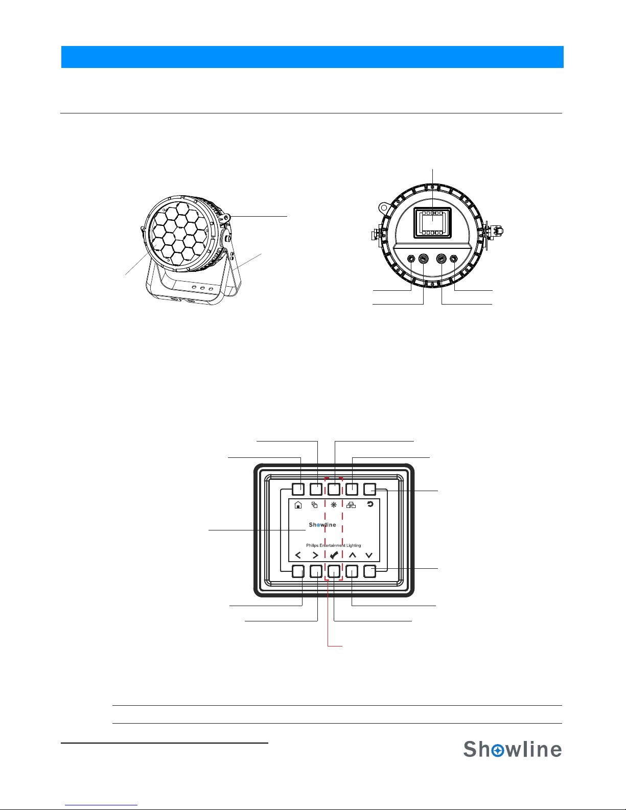
6.Master / Slave Operational Mode
The Master / Slave Operational Mode allows one SL PUNCHLITE 220 to act as the "Master" unit and all other
connected units are controlled by this unit. When a unit is set to "Slave" mode, it will only listen to and follow any
commands sent from a "Master" unit. Only one "Master" unit is allowed in this type of operation.
Figure 12: SL PUNCHLITE 220- Master / Slave Configuration
Master Unit Slave Unit Slave Unit
Note: For more information on DMX512 networking and systems, refer to "Additional Resources for DMX512" on
page 1. "DMX CONTROL" on page 16. For SL PUNCHLITE 220 DMX Mapping, refer to
Installation & User’s ManualSL PUNCHLITE 220
DMX512
DMX512 (out from first
to second luminaire)
DMX512 (out to the next
(from console or
control device)
luminaire or DMX512 controlled
device)
16 DMX Control
DMX CONTROL
This section contains information for operating the luminaire using DMX control in Simple 8-bit, RGBW 8-bit,
RGBW 16-bit or HSIC (Hue, Saturation, Intensity and Color Correction) modes. For Menu options and detailed
information, see "LCD Display and Menu System” on page 9.
Note: These tables assume a DMX start address of 1. When a different starting address is used, this address becomes
channel 1 function and other functions follow in sequence.
1. SL PUNCHLITE 220 DMX Mapping
Simple 8-Bit Mode
Table 3 provides DMX channel mapping of all DMX512 control values when the SL PUNCHLITE 220 LED
Luminaire is in simple 8-bit DMX512 mode (as set by the luminaire’s menu system).
Table 3: SL PUNCHLITE 220 DMX Channel Mapping (Simple 8 - Bit Mode)
DMX
Channel Parameter Range DMX Range%
Default - recom-
mended console
default values
Description
Master Intensity 08 bit control for Intensity of LED settings.
Strobe 0Controls strobe operations as follows . . .
Open = DMX 0 - 2
Closed = DMX 3 - 5
Slow Rand = DMX 6 - 7
Med Rand = DMX 8 - 10
Fast Rand = DMX 11 - 12
Strobe Range = DMX 13 - 127 (fastest)
Pulse + Slow Rand = DMX 128 - 129
Pulse + Med Rand = DMX 130 - 131
Pulse + Fast Rand = DMX 132 - 133
Pulse + Range = DMX 134 - 191
Pulse - Slow Rand = DMX 192 - 193
Pulse - Med Rand = DMX 194 - 195
Pulse - Fast Rand = DMX 196 - 197
Pulse - Range = DMX 198 - 255
0
0
0
0
0
0
0 - 100%
0 - 100%
0 - 100%
0 - 100%
0 - 100%
0 - 100%
0 - 100%
0 - 100%
0 - 255
0 - 255
0 - 255
0 - 255
0 - 255
0 - 255
0 - 255
0 - 255
2
1
3
4
5
7
6
8
Installation & User’s Manual
Zoom
Control
8 bit control of Red LEDs from 0 to full.
8 bit control of Green LEDs from 0 to full.
8 bit control of Blue LEDs from 0 to full.
8 bit control of White LEDs from 0 to full.
Red 1-3
Blue 1-3
Green 1-3
White 1-3
Variable control of zoom from 12 - 45
Functions of the SL Series products. Set control
channel value to desired action,hold value for at
least 5 seconds ,then turn to 0.
Set control channel value to 0 without any scaling.
Default Setting on Console = DMX 0-4
DIM Response _Normal = DMX 5 - 9
DIM Response_Incandescent = DMX 10 - 14
Dimming Curve_linear = DMX 30 - 34
Dimming Curve_Square = DMX 35- 39
Dimming Curve_S-Curve = DMX 40 - 44
Dimming Curve_PL-Curve = DMX 45 - 49
Calibration_OFF = DMX 70 - 74
Calibration_ON = DMX 75 - 79
Fan_Auto = DMX 80 - 84
Fan_Off = DMX 85 - 89
Reserves( Future use) = DMX 90 - 250
SL PUNCHLITE 220

Simple 8 BIT MODE
DMX CHANNEL 3 Group MODE 1 Group MODE
1Master Intensity Master Intensity
2Strobe Strobe
3Zoom Zoom
4Control Control
5Red_1 Red_1-3
6Green_1 Green_1-3
7Blue_1 Blue_1-3
8White_1 White_1-3
9Red_2
10 Green_2
11 Blue_2
12 White_2
13 Red_3
14 Green_3
15 Blue_3
16 White_3
2.Simple 8-Bit Group Modes
Table 4: SL PUNCHLITE 220 LED Luminaire DMX Channel Mapping (Simple 8-Bit Group Modes)
Table 4 provides DMX channel mapping of all DMX512 control values when the SL PUNCHLITE 220 LED
Luminaire is operated in various Simple 8-bit DMX512 Group Control Modes.
Master / Slave Operational Mode
Installation & User’s ManualSL PUNCHLITE 220
17
Installation & User’s ManualSL PUNCHLITE 220

SL PUNCHLITE 220 DMX Mapping
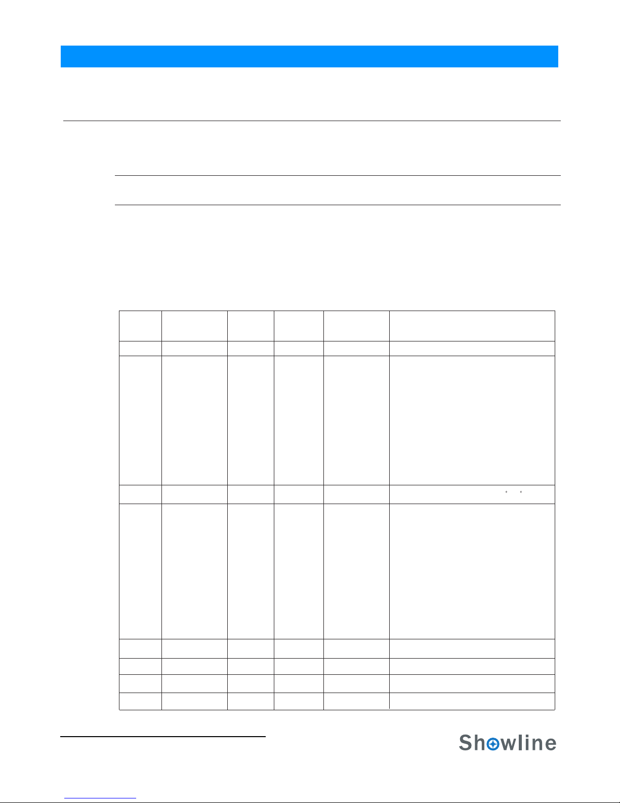
3. RGBW 8 - Bit Mode
Table 5 provides DMX channel mapping of all DMX512 control values when the SL PUNCHLITE 220 LED
Luminaire is in RGBW 8-bit DMX512 mode (as set by the luminaire’s menu system).
DMX
Channel Parameter Range DMX Range%
Default - recom-
mended console
default values
Description
2Color Presets
1 0-255
0-255
0-100%
0-100%
0
0
DMX 0 - 4Channel OFF (disabled)
DMX 87 - 88CF_9_White 3000K
DMX 85 - 86CF_8_White 3200K
DMX 83 - 84CF_7_White 4000K
DMX 81 - 82CF_6_White 4500K
DMX 79 - 80CF_5_White 5000K
DMX 77 - 78CF_4_White 5600K
DMX 75 - 76CF_3_White 6500K
DMX 73 - 74CF_2_White 8000K
DMX 71 - 72CF_1_White 10000K
DMX 69 - 70CF_0_Color OFF
DMX 67 - 68Preset 31
DMX 65 - 66Preset 30
DMX 63 - 64Preset 29
DMX 61 - 62Preset 28
DMX 59 - 60Preset 27
DMX 57 - 58Preset 26
DMX 55 - 56Preset 25
DMX 53 - 54Preset 24
DMX 51 - 52Preset 23
DMX 49 - 50Preset 22
DMX 47 - 48Preset 21
DMX 45 - 46Preset 20
DMX 43 - 44Preset 19
DMX 41 - 42Preset 18
DMX 39 - 40Preset 17
DMX 37 - 38Preset 16
DMX 35 - 36Preset 15
DMX 33 - 34Preset 14
DMX 31 - 32Preset 13
DMX 29 - 30Preset 12
DMX 27 - 28Preset 11
DMX 25 - 26Preset 10
DMX 23 - 24Preset 9
DMX 21 - 22Preset 8
DMX 19 - 20Preset 7
DMX 17 - 18Preset 6
DMX 15 - 16Preset 5
DMX 13 - 14Preset 4
DMX 11 - 12Preset 3
DMX 9 - 10Preset 2
DMX 7 - 8Preset 1
DMX 5 - 6Preset 0 (OFF)
DMX 89 - 90CF_10_White 2700K
Variable Color Presets as follows...
Master Intensity- High 8 bit control for Intensity of LED settings.
18
Installation & User’s Manual SL PUNCHLITE 220
Table 5: SL PUNCHLITE 220 DMX Channel Mapping (RGBW 8-Bit Mode)
Table of contents
Other Showline Lighting Equipment manuals


Popular Lighting Equipment manuals by other brands

Avantes
Avantes AvaLight-CAL Safety instructions

B-K lighting
B-K lighting TETON installation instructions

Lightolier
Lightolier ProSpec Track Lighting FIXTURE installation instructions

PSL
PSL CONOPLUS GREEN D0004 user manual

UWE
UWE JetStream BAMBO2 Installation and operating instructions

Blizzard Lighting
Blizzard Lighting Puck Pro Zoom EXA user guide


Luminetic
Luminetic SLP Series instruction manual

ThePondguy
ThePondguy 160326 instruction manual

Pentair Pool Products
Pentair Pool Products PG2000 840240 installation manual

NANLITE
NANLITE Forza 720B user manual

Soundoff Signal
Soundoff Signal Pinnacle EPL7000 Series instruction sheet

Inspire
Inspire LEDFLEXI 2128KS-1.5-RGBW-P instruction manual