Sphere ST-PS5 User manual

SPHERE Portable Traffic Signals
Model: ST-PS5 / Technical Specifications, Instruction Manual and Warranty Card
1
PORTABLE TRAFFIC SIGNALS
Model: ST-PS5
Technical Specifications, Operation Manual and
Warrany Card
Document date: 2020/29/06 © Copyright SPHERE j.d.o.o.
Document produced by SPHERE® (www.sphere.hr).

Table of Contents
SPHERE Portable Traffic Signals
Model: ST-PS5 / Technical Specifications, Instruction Manual and Warranty Card
2
Table of Contents
Table of Contents.................................................................................................................................... 2
1. Introduction ........................................................................................................................................ 4
1.1. Objectives .................................................................................................. 4
1.2. Scope ......................................................................................................... 4
1.3. Introduction ............................................................................................... 4
2. Design and Features ........................................................................................................................... 5
2.1. Design & Construction .................................................................................. 5
2.2. LED Technology ........................................................................................... 7
2.3. Operator Interface ....................................................................................... 8
2.3.1. PHASE ............................................................................................................................................................................. 9
2.3.2. MODE ........................................................................................................................................................................... 10
2.3.3. TIME ADJUSTMENT – Clearance Time/All-Red ............................................................................................................ 11
2.3.4. TIME ADJUSTMENT – Add Seconds 1-9 ....................................................................................................................... 13
2.3.5. TIME ADJUSTMENT – Green ........................................................................................................................................ 14
2.3.6. TIME ADJUSTMENT – Channel Selection ..................................................................................................................... 15
2.3.7. WARNING ..................................................................................................................................................................... 16
2.3.7.1 Emergency Mode Synchronize Error .................................................................................................................... 16
2.3.7.2 System Fault ......................................................................................................................................................... 16
2.3.7.3 Battery Status ....................................................................................................................................................... 16
2.3.7.4 Reversed Battery Polarity ..................................................................................................................................... 16
2.3.7.5 System Status Indicator ........................................................................................................................................ 17
2.3.7.6 Radio Error or Wrong Channel Selected .............................................................................................................. 17
2.4. Microprocessor Technology ......................................................................... 17
2.5. Low Power Consumption ............................................................................. 17
2.6. Auto-Brightness Technology......................................................................... 17
3. Setup of Portable Traffic Signals ........................................................................................................ 18
3.1. Installing the Signal Head with Pole to the Battery Box .................................... 18
3.2. Connecting the Signal Head Cable with the Battery Box Socket .......................... 18
3.3. Battery Installation .................................................................................... 18
4. Operational Modes ........................................................................................................................... 20
4.1. Radio Operational Mode (The Default Operational Mode) ................................. 20
4.1.1 FIXED TIME .................................................................................................................................................................... 21
4.1.2. MANUAL GREEN .......................................................................................................................................................... 22
4.1.3. MANUAL RED ............................................................................................................................................................... 22
4.1.4. MANUAL ALL-RED ........................................................................................................................................................ 23
4.1.5. FLASHING AMBER ........................................................................................................................................................ 23
4.1.6. LAMPS OFF ................................................................................................................................................................... 24
4.2. Radar Mode .............................................................................................. 25
4.2.1. 2-WAY .......................................................................................................................................................................... 25
4.2.2. DAISY CHAIN ................................................................................................................................................................ 26
4.2.2.1 Setting up the MASTER Unit (Daisy Chain) ........................................................................................................... 27
4.2.2.2 Setting up the SLAVE Units (Daisy Chain) ............................................................................................................. 28
4.2.2.3. Setting Up the Desired Signal Phases for the Daisy Chain Operational Mode .................................................... 29
4.3. Emergency Mode (Non-Radio Mode) .............................................................. 30

Table of Contents
SPHERE Portable Traffic Signals
Model: ST-PS5 / Technical Specifications, Instruction Manual and Warranty Card
3
5. Troubleshooting ................................................................................................................................ 32
5.1. Radio Communication Failure ...................................................................... 32
5.1.1 Temporary Loss of Radio Communication Between MASTER and SLAVE .................................................................... 32
5.1.2 Permanent Loss of Radio Communication Between MASTER and SLAVE .................................................................... 32
5.1.3 Permanent Loss of Communication Between MASTER and SLAVES in a Daisy Chain Operational Mode .................... 33
5.2. Radar Failure ............................................................................................ 34
5.3. Low Battery Error ...................................................................................... 34
5.4. Lights OFF/2 Lights ON Hazard Condition ....................................................... 34
6. Warranty Card .................................................................................................................................. 35
6.1. Warranty Card ........................................................................................... 35
7. Terms and Conditions........................................................................................................................ 36
7.1. Application ............................................................................................... 36
7.2. Copyright ................................................................................................. 36
7.3. Trademarks ............................................................................................... 36
7.4. Safety ...................................................................................................... 36
7.5. Limited Warranty ....................................................................................... 36
7.6. Liability Limit and Indemnity ....................................................................... 36

1. Introduction
SPHERE Portable Traffic Signals
Model: ST-PS5 / Technical Specifications, Instruction Manual and Warranty Card
4
1. Introduction
1.1. Objectives
The objective of this document is to give technical information about PORTABLE TRAFFIC SIGNALS ST-PS5 and describe steps
to setup and operate the device.
1.2. Scope
This document will describe the design, features, dimensions, technical specifications, setup and operational modes of the ST-
PS5 Portable Traffic Signals. Further information can be acquired on the web site or directly with manufacturers.
1.3. Introduction
The Sphere ST-PS5 Portable Traffic Signals is a modular mobile traffic signal system intended to be applied primarily to shuttle
the control of vehicular traffic at road works or bridge works.
Road works where Portable Traffic Signals are applied have a a section of the carriage-way closed, so the single lane must be
used alternatively by traffic from the opposite directions.
Other than vehicle-actuated alternating one-way traffic, the ST-PS5 can also be used for controlling the T-junction situations,
crossroads traffic and roundabouts, with up to 7 signals operating simultaneuosly in a Daisy Chain operational mode.
The ST-PS5 Portable Traffic Signals are equipped with a directional radar for vehicle-actuated operation, radio communication
with a range of up to 1000 m under ideal conditions and emergency mode for quartz control when the radio communication
is faulty.

2. Design and Features
SPHERE Portable Traffic Signals
Model: ST-PS5 / Technical Specifications, Instruction Manual and Warranty Card
5
2. Design and Features
2.1. Design & Construction
When dismounted, Portable Traffic Signals ST-PS5 consists of two separate parts:
1. Signal head made from powder-coating steel consisting of 3 integrated LED signal aspects, 1 vehicle detector, 1 RF
antenna and a built-in steel pole (PICTURE 1)
2. Battery box which consists of built-in watertight electronics and a watertight Operator Interface consisting of
operational interface, space for rechargeable battery, two battery clamps to connect the rechargeable battery to the
system, rear transport handle and two never-flat rubber wheels (PICTURE 1).
PICTURE 1: ST-PS5 Signal Head, Buil t-In S teel Pole and Battery C ase

2. Design and Features
SPHERE Portable Traffic Signals
Model: ST-PS5 / Technical Specifications, Instruction Manual and Warranty Card
6
SPECIFICATION
Model ST-PS5
O p e r a t i o n a l V o l t a g e 12 V D C r e ch ar ge a b l e b a t t er y
L E D P o w e r C o n s u m p t i o n I m a x 0 .7 1 A d a y ti m e mo d e . I m a x 0. 0 8 A ni g ht - t i me m od e
R u n t i m e o n a S i n g l e
C h a r g e ( D a y s ) Up t o 25 d ay s ( 0- 2 4 h 1 8 0 A h )
L E D T y p e W i d e v ie w i n g a n g l e S M D L ED s
L i g h t S o u r c e s 10 5 L EDs p e r g r e e n a nd re d s e gm e nt . 1 9 0 L ED s o n a mb er s e g me n t
S i g n a l A s p e c t D i a m e t e r 21 0 m m
L u m i n o s i t y 84 0 C d p e r s e gm e n t
B r i g h t n e s s Gr a d u a l L ED b ri gh t n e s s ad jus t m e n t
H o u s i n g P o w d e r c oati ng s t e e l
F e a t u r i n g D e tac h ab le s i gn a l h e a d /o os t , m o d u la r co m p o n e nts
T r a n s p o r t H e i g h t 22 0 0 m m
T r a n s p o r t W i d t h 68 5 m m
T r a n s p o r t W e i g h t 61 kg
S y s t e m F o o l p r o o f s y s te m, b at t e r y s t a tu s , st at u s mo ni t o ri n g , s y ste m m o ni to r i ng ,
o v e r - d is c ha rge p r o te c t i o n , e a s y us e lo ck in g sy s t e m, re v e rse d b a t t e ry
p o l ar i ty pr ote c t i o n
D e f a u l t
O p e r a t i o n a l
F r e q u e n c y 43 3 M H z ( A d jus ta b l e )
R F C h a n n e l s 16 C h a n n e ls
R F R a n g e Up t o 1 0 00 m u n d e r id e a l c o n d itio ns
R a d i o O p e r a t i o n a l M o d e s
2
-
wa y r a d a r m o de , d a i s y c hai n r a d a r m od e, f
i x ed t i me ,
m a n ua l
al l
-
r e d ,
m a nu al r ed , m an u a l gr e en, f l a s hi n g a m b e r , l am ps o ff
N o n
-
R a d i o
O p e r a t i o n a l
M o d e s Em e r ge n c y m o d e
R a n g e o f A p p l i c a t i o n s
Si n g l e la n e ,
T
-
ju nc ti on , c r os s ro ad , ro u n d a bo u t s. U p t o 7 u n i ts s u pp o r t e d i n
d a i s y c ha i n o pe r a t i on al m od e .
E U D e c l a r a t i o n o f
C o n f o r m i t y
ET S I E N 30 1 48 9
-
1 v 2 . 2. 0 ( 2 017) , ET S I E N 30 1 4 89
-
3 v 2.1 . 1 ( 2 0 1 7 ) , EN
50 2 9 3 : 2 0 1 2
A d d i t i o n a l U p g r a d e s Co u n td o wn t i m e r , a d ju s t a b l e p o le
TABLE 1. ST-PS Technical Specification
DIMENSIONS & WEIGHT
Model ST-PS5
T o t a l H e i g h t 210 cm
B a t t e r y B o x W i d t h 76 c m
B a t t e r y B o x L e n g t h 68 c m
B a t t e r y B o x H e i g h t 41 . 5 c m
B a s i c W e i g h t 61 kg
T r a n s p o r t W e i g h t s 61 kg
TABLE 2. ST-PS Dimensions & Weight

2. Design and Features
SPHERE Portable Traffic Signals
Model: ST-PS5 / Technical Specifications, Instruction Manual and Warranty Card
7
2.2. LED Technology
Portable Traffic Signals ST-PS5 signal aspects are made in high quality integrated LED (
light-emitting diode
) technology which
has up to five times lower power consumption than the standard halogen bulbs, as well as significantly longer lifespan.
PICTURE 2: Portable Traffic Si gnals ST -PS5 – LED Signal Aspects

2. Design and Features
SPHERE Portable Traffic Signals
Model: ST-PS5 / Technical Specifications, Instruction Manual and Warranty Card
8
2.3. Operator Interface
The operator interface of ST-PS5 was designed and developed in a large way by listening to recomendations and advices of the
road construction workers, who demanded simple, intuitive, precise and fast entering of the desired operational settings.
PICTURE 3: Ope rator Interface – MASTER
PICTURE 4: Operator Inte rface – S LAVE
The operator interface of ST-PS5 is divided into 4 FUNCTIONAL SECTIONS for easier navigation:
1. PHASE section (RED, AMBER or GREEN phase indicators)
2. MODE section for choosing the desired operational mode
3. TIME ADJUSTMENT section for choosing the duration of ALL-RED/CLEARANCE TIME (secs) and the duration of GREEN
(secs)
4. WARNING section
2. Design and Features
SPHERE Portable Traffic Signals
Model: ST-PS5 / Technical Specifications, Instruction Manual and Warranty Card
9
The Operator Interface of ST-PS5 consists of three multifunctional rotary knobs:
1. On the TIME ADJUSTMENT section, the CLEARANCE TIME/ALL-RED knob is used to set the duration of CLEARANCE
TIME/ALL-RED phase in seconds
2. On the TIME ADJUSTMENT section, the GREEN knob is used to set the duration of GREEN phase in seconds
3. On the MODE section, the MODE knob is used to set the desired operational mode
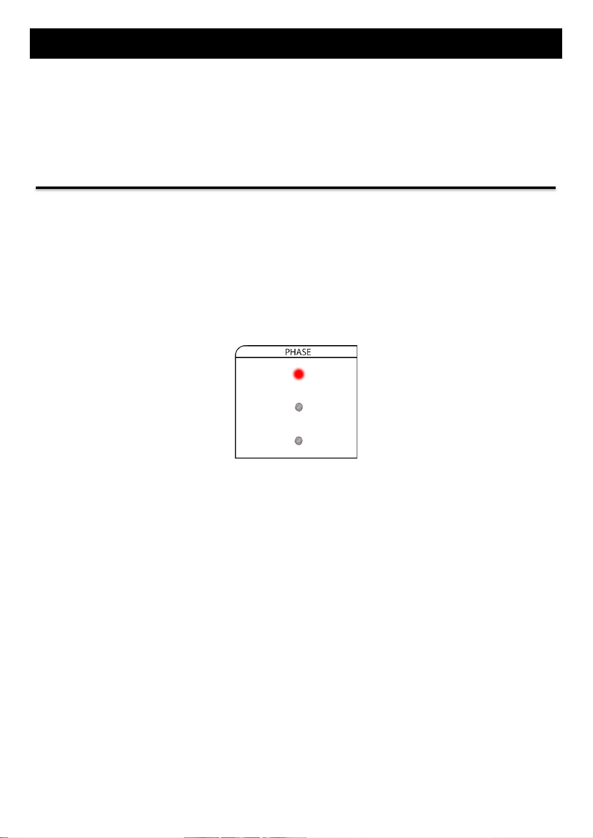
2.3.1. PHASE
On both Master and Slave controllers, the PHASE section provides indication of which aspect is on.
The PHASE section mimics the following signal head aspects:
1. RED
2. AMBER
3. GREEN
On both Master and Slave, coloured ultra bright LEDs (which represent the signal head) provide indication of which aspect is
ON.
Phase se ction on t he Operator interface – RED signal aspect i s ON

2. Design and Features
SPHERE Portable Traffic Signals
Model: ST-PS5 / Technical Specifications, Instruction Manual and Warranty Card
10
2.3.2. MODE
There must be only one Master controller in the system.
To select the operational mode, move the MODE knob to the corresponding mode position (e.g. to use the portable traffic
signals in a 2-WAY RADAR mode, move the MODE knob on both MASTER and SLAVE units to the position 2-WAY RADAR
MODE)
MASTER SLAVE
Selecting the 2-Way Radar Mode on MASTER and SL AVE units
You can choose between one of the following operational modes:
PICTURE 7. Operational Modes for Master Unit and Slave Unit(s)
The upper diagram shows all available operational modes and how to pair them (e.g. to use the MANUAL GREEN operational
mode, move the MODE knob on the MASTER unit to the position MANUAL GREEN and move the MODE knob on the SLAVE unit
to the position FIXED TIME).
The SLAVE TOTAL/SLAVE ID positions are for DAISY CHAIN programming, while STANDBY position is for EMERGENCY MODE
only.
For a detailed instruction for each operational MODE, skip to the paragraph 4. Operational Modes.
2. Design and Features
SPHERE Portable Traffic Signals
Model: ST-PS5 / Technical Specifications, Instruction Manual and Warranty Card
11
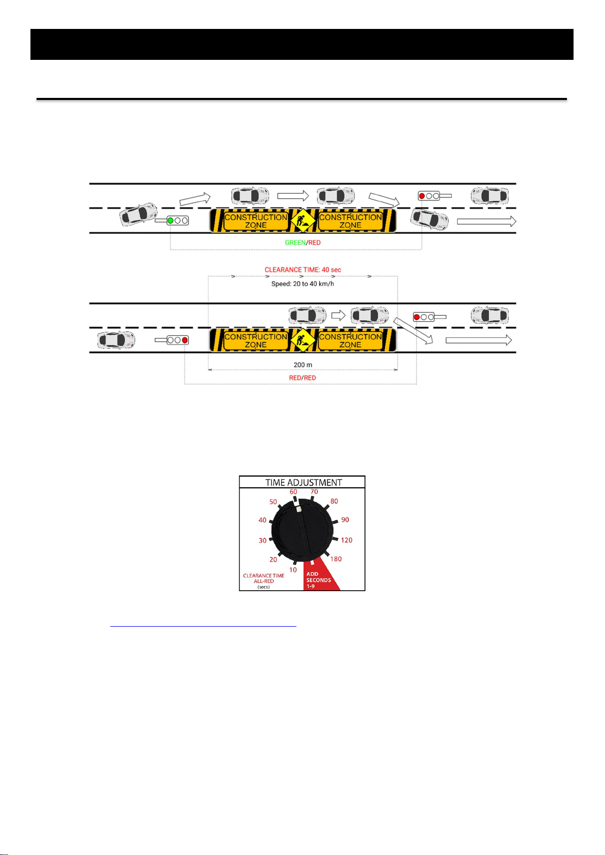
2.3.3. TIME ADJUSTMENT – Clearance Time/All-Red
The CLEARANCE TIME (ALL RED) is the time interval allotted for vehicles to safely pass through the one-lane construction zone
before opposing traffic is released. During CLEARANCE TIME (ALL RED) the red displays are shown to all approaches.
PICTURE 5. CLEARANCE TIME (ALL RED) ensures that the traffic withi n the workzone have enough time to clear
the w orkzone before the other lights turn green
You can set the timing of CLEARANCE TIME (ALL RED) from 10 -180 seconds by rotating the corresponding knob to the
desired setting.
If the duration of CLEARANCE TIME/ALL-RED must be set between 11-189 seconds, e.g. 73 seconds instead of 70 or 80, move
to the paragraph 2.3.4. TIME ADJUSTMENT --- Add Seconds 1-9.

2. Design and Features
SPHERE Portable Traffic Signals
Model: ST-PS5 / Technical Specifications, Instruction Manual and Warranty Card
12
Travel
Distance Vehicle Speed (km/h)
(m) 15 km/h 20 km/h 25 km/h 30 km/h 40 km/h 50 km/h 60 km/h
25 10 9 8 7 6 6 6
50
16 13 11 10 9 8 7
100
28 22 18 16 13 11 10
150 40 31 26 22 18 15 13
200 52 40 33 28 22 18 16
250 64 49 40 34 27 22 19
300 76 58 47 40 31 26 22
350
88 67 54 46 36 29 25
400
100 76 62 52 40 33 28
500 124 94 76 64 49 40 34
600 148 112 90 76 58 47 40
700 172 130 105 88 67 54 46
800
196 148 119 100 76 62 52
900
220 166 134 112 85 69 58
1000
244 184 148 124 94 76 64
Table fo r adjusting the Clearance Times (in second s)

2. Design and Features
SPHERE Portable Traffic Signals
Model: ST-PS5 / Technical Specifications, Instruction Manual and Warranty Card
13
2.3.4. TIME ADJUSTMENT – Add Seconds 1-9
If there is a strict need for the duration of CLEARANCE TIME/ALL-RED to be set between 11 and 189 seconds, you can use the
ADD SECONDS 1-9 option.
E.g. there is a need for the duration of CLEARANCE TIME/ALL-RED to be set at 75 seconds instead of 70 or 80 as predefined on
the operator interface:
1. Move the CLEARANCE TIME/ALL-RED knob to the position ADD SECONDS 1-9
2. On the amber light, the countdown timer will commence counting from 1 to 9 where each number represents the
additional second
3. When the desired additional second is displayed (e.g. 5 seconds), move the CLEARANCE TIME/ALL-RED knob
backwards. This procedure memorizes and adds the additional 5 seconds to each entered duration of CLEARANCE
TIME/ALL-RED phase
4. Move the CLEARANCE TIME/ALL RED knob to the position 70, and the 5 seconds of additional time will be
automatically added, thus resulting in 75 seconds of clearance time
If you want to remove the additional seconds feature, you can either move the CLEARANCE TIME/ALL-RED knob to the
position ADD SECONDS 1-9 and then immediately move it backwards before the countdown from 1-9 commences, or simply
RESET the portable traffic signals by reconnecting the battery clamp to the battery.

2. Design and Features
SPHERE Portable Traffic Signals
Model: ST-PS5 / Technical Specifications, Instruction Manual and Warranty Card
14
2.3.5. TIME ADJUSTMENT – Green
The GREEN rotary knob is used to set the duration of GREEN phase after which the signal head will turn to 3 seconds AMBER,
and then RED (in the EU version, otherwise according to the corresponding national regulations).
You can set the duration of GREEN time by rotating the corresponding knob to the desired setting.
In RADAR MODE, the GREEN phase runs as maximum green phase, depending on the volume of traffic.
The minimum green phase always runs and is factory set at 12 seconds and is non-adjustable.
The green phase is extended by the oncoming vehicles that trigger the radar detectors up to the maximum green
phase which is user user-adjustable and can be set from 20-240 seconds.
If no more vehicles are registered between the minimum and maximum green phase, the current green phase is
ended.
In FIXED TIME, the GREEN phase runs according to the fixed setting regardless of the volume of traffic.
The duration of each GREEN phase is the same, and is user-adjustable ranging from 20-240 seconds.

2. Design and Features
SPHERE Portable Traffic Signals
Model: ST-PS5 / Technical Specifications, Instruction Manual and Warranty Card
15
2.3.6. TIME ADJUSTMENT – Channel Selection
You can use the CHANNEL SELECTION feature if you have more than one set of Portable Traffic Signals close to each other and
you want them to operate independently from each other in radio operational mode.
You can choose between channels ranging from 1 to 16, where channel No.1 has a frequency of 433.00 MHz, up to a channel
No.16, which has a frequency of 434.60 MHz.
E.g. to program the channel No. 12 on the portable traffic signals:
1. Move the GREEN knob to the position CHANNEL SELECTION
2. On the amber light, the countdown timer will commence counting from 1 to 16 where each number represents one
of the available channels for selection
3. When the desired channel is displayed (e.g. 12), move the green knob to green time setting.
This procedure permanently stores the channel number into the memory of the portable traffic signals.
If you want to program another channel into the portable traffic signals, repeat the above procedure, with the new channel
number.

2. Design and Features
SPHERE Portable Traffic Signals
Model: ST-PS5 / Technical Specifications, Instruction Manual and Warranty Card
16
2.3.7. WARNING
For a more detailed solutions regarding the WARNING fault indicators, please skip to the paragraph 5 --- TROUBLESHOOTING.
2.3.7.1 Emergency Mode Synchronize Error
If the EMERGENCY MODE SYNCHRONIZE ERROR indicator starts to blink, that means that the unit is not properly
synchronized to operate in an Emergency mode. This happens if the operational mode knob is set on the STANDBY position,
or if the time phases have been altered after the initial Emergency Mode synchronization.
SOLUTION: Synchronize the unit / Skip to paragraph 4.2. on how to synchronize portable traffic signals in an Emergency
Mode.
2.3.7.2 System Fault
If the SYSTEM FAULT indicator is illuminated in red, that means that the main processor of the controller is faulty.
SOLUTION: Request service / return. Replace controller.
2.3.7.3 Battery Status
The BATTERY STATUS indicator displays in green, amber or red colour the voltage of the battery.
BATTERY WITH
GREATER THAN 20%
OPERATIONAL
CAPACITY
BATTERY AT LESS
THAN 20%
OPERATIONAL
CAPACITY
BATTERY LOW
Recharge ASAP.
BATTERY
DEPLETED.
Signal heads OFF.
Recharge immediately.
> 12 V 12 V – 11.5 V 11.5 V – 11.0 V < 11.0 V
2.3.7.4 Reversed Battery Polarity
If the battery connections are connected to the wrong polarity of the rechargeable battery, the REVERSED BATTERY
POLARITY will illuminate in RED colour.
Integrated safety measure prevents the damage of the portable traffic signals if the battery connections are connected to the
wrong polarity of the rechargeable battery.
SOLUTION: Connect the RED BATTERY CLAMP to the (+) positive polarity and the BLACK BATTERY CLAMP to the (---)
negative polarity of the battery.

2. Design and Features
SPHERE Portable Traffic Signals
Model: ST-PS5 / Technical Specifications, Instruction Manual and Warranty Card
17
2.3.7.5 System Status Indicator
The SYSTEM STATUS INDICATOR illuminates in 3 colours:
GREEN
(Displays on Master unit
only)
BLUE
(Displays on Master unit
only)
MAGENTA
Vehicle detected
SLAVE
Vehicle detected
MASTER
Radio
Communication
Error in Daisy
Chain
(View Troubleshooting)
2.3.7.6 Radio Error or Wrong Channel Selected
The illuminated RADIO ERROR or WRONG CHANNEL SELECTED means that either:
1. The Radio Communication between MASTER and SLAVE(s) has been lost or
2. The units have different channels programmed (e.g. The Master operates on Channel No.7, while the Slave operates
on Channel No. 11)
SOLUTION: Check the paragraph 5 --- TROUBLESHOOTING.
2.4. Microprocessor Technology
The functions of the Portable Traffic Signals ST-PS5 are operated by a modern microcontroller who controls and permanently
checks the functionality of the entire device. If any irregularity occurs, ST-PS5 immediately displays an error message on the
operator interface and immediately transitions to FLASHING AMBER condition.
The microcontroller and the circuit board in the controller are sealed in a special waterproof case for increased safety.
2.5. Low Power Consumption
With a single battery charge of 180Ah, the ST-PS5 can have a running time of up to 25 days.
2.6. Auto-Brightness Technology
Our own developed AUTO-BRIGHTNESS technology keeps the brightness of the signal aspects always at the optimum level.

3. Setup of Portable Traffic Signals
SPHERE Portable Traffic Signals
Model: ST-PS5 / Technical Specifications, Instruction Manual and Warranty Card
18
3. Setup of Portable Traffic Signals
3.1. Installing the Signal Head with Pole to the Battery Box
Mount the signal head with the pole into the battery box like on the pictures below:
3.2. Connecting the Signal Head Cable with the Battery Box Socket
To connect the communication cable from the signal head to the battery box:
1. Insert the communication cable from signal head to the battery box socket
2. Screw the threaded joint clockwise
3.3. Battery Installation
To install the rechargeable battery into the battery box, you must place the battery inside the space provided by the battery
box.
Battery Box
SPACE FOR RECHARGEABLE BATTERY

3. Setup of Portable Traffic Signals
SPHERE Portable Traffic Signals
Model: ST-PS5 / Technical Specifications, Instruction Manual and Warranty Card
19
To connect the rechargeable battery with the Portable Traffic Signals ST-PS5, use the provided BATTERY CONNECTIONS and
connect them with the battery poles of the Rechargeable Battery:
1. RED BATTERY CONNECTION to the POSITIVE (+) polarity of the battery
2. BLACK BATTERY CONNECTION to the NEGATIVE (-) polarity of the battery.
Connect the RE D BATTERY C LAMP t o the (+) Positive Polarity and BLA CK BATTERY CLAMP to the (–)
Negative Polari ty of the Battery
As soon as the battery is connected, the system powers ON.
RED
BATTERY
CLAMP
BLACK
BATTERY
CLAMP
(+) POSITIVE
POLARITY OF
THE BATTERY
(-) NEGATIVE
POLARITY OF
THE BATTERY

4. Operational Modes
SPHERE Portable Traffic Signals
Model: ST-PS5 / Technical Specifications, Instruction Manual and Warranty Card
20
4. Operational Modes
You can use the portable traffic signals in:
Radar Mode (Radio Communication with Radar)
Radio Operational Mode (Radio Communication without Radar)
Emergency Mode (Use when the radio communication between master and slave(s) is faulty).
RADAR MODE RADIO OPERATIONAL
MODE
EMERGENCY MODE
(Non-Radio Mode)
2-WAY (OPTIONAL)
DAISY CHAIN (OPTIONAL)
FIXED TIME
MANUAL GREEN
MANUAL RED
MANUAL ALL-RED
FLASHING AMBER
LAMPS OFF
DAISY CHAIN (OPTIONAL)
EMERGENCY MODE
4.1. Radio Operational Mode (The Default Operational Mode)
Sphere portable traffic signals are fitted with a 433.05-434.79MHz antenna that provides reliable wireless radio
communication between portable traffic signal units. For the best results, the portable traffic signal units should be
positioned line-of-sight to each other. A maximum range of up to 1 kilometer between the Master and Slave(s) can be
achieved in ideal conditions.
Portable traffic signals must be set on the same channel for a wireless communication to be established between Master and
Slave(s).
When using the Sphere Portable Traffic Signals in a Radio Operational Mode, the MASTER unit controls the SLAVE unit(s) via
Radio Linked Communication, meaning that setting the operational modes or time phases is done exclusively on the MASTER
unit.
MASTER --- The Master controller determines the overall operation of the system according to the selected configuration,
mode and time settings. There must be only one Master controller in the system.
SLAVE - Slaves are primary controllers which signal as instructed by the Master controller. The operator can't control the
signal timings on Slave units in a radio operational mode.
The operator sets the timings of ALL RED/CLEARANCE TIME and GREEN exclusively on the MASTER unit, which when set, will
result in the immediate synchronization of all units connected via radio link (1 Master and 1 or more Slaves).
You can use 1 Master unit with:
1 Slave unit in a FIXED TIME operational mode
1 Slave unit in a 2-Way RADAR operational mode
Up to 6 Slaves in a DAISY CHAIN operational mode.
IN A RADIO OPERATIONAL MODE, SETTING UP THE
OPERATIONAL MODES (fixed time, 2-way radar,
manual green…) OR TIME PHASES (clearance
time/all-red, green) IS DONE EXCLUSIVELY ON THE
MASTER UNIT!
IMPORTANT
Table of contents
Popular Lighting Equipment manuals by other brands

FOS Technologies
FOS Technologies PAR 18x10W Flat manual

Aqua Medic
Aqua Medic LED FA 100 flex Operation manual

C.P. Electronics
C.P. Electronics EBR-4SC Product guide

S.R.Smith
S.R.Smith SWIM CLUB II FUNSLIDE owner's manual

American DJ
American DJ Warp FX User instructions

NX
NX Smart Home NX-PTY10 user manual


