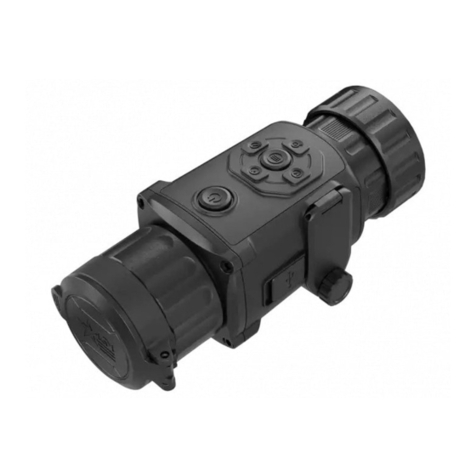
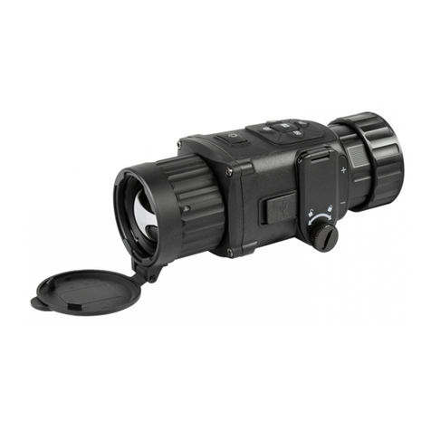
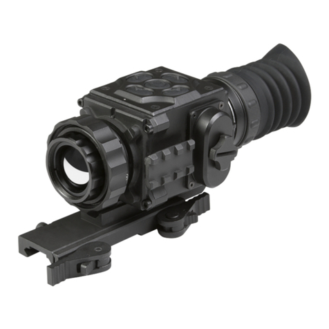
AGM Global Vision ANACONDA-MICRO User manual

USER MANUAL
ANACONDA-MICRO
THERMAL IMAGING CLIP-ON SYSTEM

© 2019 AGM Global Vision. All rights reserved worldwide.
This documentation is subject to change without notice.
No parts of this manual, in whole or in part, may be copied, photocopied, translated,
or transmitted by any electronic medium or in machine-readable form without the
prior written permission of AGM Global Vision.
If you have questions that are not covered in this manual, or need service, contact
AGM Global Vision customer support for additional information prior to returning a
product.
AGM Global Vision
173 West Main Street
PO Box 962
Springerville, AZ 85938
Tel. 928.333.4300
support@agmglobalvision.com
www.agmglobalvision.com
EXPORT INFORMATION
Buyer acknowledges that all products supplied by AGM Global Vision are subject to U.S.
export control laws, including, but not limited to, the Export Administration Regulations, the
International Economic Emergency Powers Act, and various U.S. embargoes and sanctions.
AGM Global Vision products may not be exported, re-exported, or transferred contrary to U.S.
export control laws. In particular, AGM Global Vision products may not be exported, re-export-
ed, or transferred to prohibited countries, individuals, organizations, or entities, including but
not limited to those individuals and entities listed on the List of Specially Designated Nationals
and Blocked Persons administered or maintained by the U.S. Office of Foreign Assets Control
(“OFAC”), the various lists maintained by the Bureau of Industry and Security of the Department
of Commerce, and the U.S. State Department and Buyer represents and warrants that neither
Buyer nor any of its officers, directors, or employees are on such lists. Distribution or resale by
Buyer to such countries, individuals, organizations, or entities is expressly prohibited. Buyer
has and will maintain a positive process to ensure compliance with this Section.
2020.12.08

3
Anaconda-Micro USER MANUAL
LIST OF CONTENTS
TITLE PAGE
Safety Summary 4
1. GENERAL INFORMATION 5
1.1 System Description 5
1.2 Main Features 5
1.3 Main Parts and Components 5
2. OPERATING INSTRUCTIONS 7
2.1 Installation and Mounting 7
2.2 Controls and Indication 11
2.3 Operating 16
3. WARRANTY INFORMATION 21
3.1 Warranty Information and Registration 21
4. SPECIFICATIONS 23
4.1 Specifications 23

4AGM Global Vision
SAFETY SUMMARY
The proper usage of the device is important for safe exploitation!
Therefore read carefully the present manual!
WARNING:
If the device was left in storage for a longer period of time, before exploitation check
its functionality.
WARNING:
Disassembling of the device is prohibited, except in authorized repair centers.
WARNING:
The external optical surfaces should be clean at all times. Touching the optical
surfaces with bare hands is not recommended.
WARNING:
Sand and sea water can damage the optical coatings!
WARNING:
Do not point the device directly at the sun!
WARNING:
Image performance is dependent on scenery and atmosphere conditions. Contrast in
the same image may vary as a function of the time of day due to the effect of the sun.
For example, at sunset objects will have absorbed different levels of heat resulting in
greater temperature differences and better contrast.
WARNING:
When left in storage for a longer period of time, batteries have to be removed and
stored in polyethylene bags to prevent contact with metal.
WARNING:
When carrying or transporting the device, put the protective lens cap!
WARNING:
Condensation can cause fogging of the optical surfaces! Condensation occurs when
the temperature or humidity changes as follows:
– When moving the device from cold to warm place or vice versa;
– In places with high humidity.
When equalizing the temperature of the device with the environmental, the condensa-
tion disappears. Use the towel to remove moisture.
WARNING:
Clean the lens surfaces with the lens cloth or with the napkin!
LEGAL NOTICE:
Before attaching to weapons, check the regional legal regulations in the area of ap-
plication. The attachment to a weapon is always the sole responsibility of the user.

5
Anaconda-Micro USER MANUAL
1 GENERAL INFORMATION
1.1 SYSTEM DESCRIPTION
The AGM Anaconda-Micro is a compact thermal imaging clip-on system that allows
quick transformation of the day optics into thermal imaging device without any spe-
cial skills. Anaconda-Micro can be easily attaching on up to 8x magnification scopes
for medium range use and 24 hours operation under any weather and environmental
conditions.
Powered with two CR123 batteries the AGM Anaconda-Micro gives up to 5 hours of
continues work. An external 5 V power bank ( battery pack) can be easily connected via
an USB connector for a significant increase of operating time. Onboard Wi-Fi module
for live video streaming and video/images recording via application are also available.
1.2 MAIN FEATURES
• Quick conversion of daytime optics into thermal imaging scope
• Mounts in front of any daytime scope, no re-zeroing is required
• Electronic accuracy correction
• Lightweight and compact design
• Easy to operate control panel
• Automatic or manual (silent) calibration
• High resolution OLED display
• Wi-Fi data transmission
• Video/images recording
• Waterproof, shockproof
• Powered by two standard CR123A batteries
• External power supply capability
• Video output for external monitor or recorder
• Limited 3-year warranty
1.3 MAIN PARTS AND COMPONENTS
The Anaconda-Micro is shown in Figure 1-1. The ITEM column of Table 1-1 indicates the
number used to identify items in Figure 1-1.

6AGM Global Vision
TABLE 1-1. ANACONDA-MICRO MAIN PARTS AND COMPONENTS
ITEM DESCRIPTION ITEM DESCRIPTION
1Lens Cover 11 Video Cable
2Objective Focus Ring 12 Lens Tissue
3Mount 13 User Manual
4Operation Joystick 14 Carrying Bag
5Wi-Fi Antenna 15 Small Day Scope Adapter
42-50 mm (Optional)
6Attachment Place
7Extension Interface 16 Middle Day Scope Adapter
51-59 mm (Optional)
8Battery Compartment Cover
9
USB and Video Connectors
(Closed with a Cover) 17 Large Day Scope Adapter
60-65 mm (Optional)
10 USB Cable 18 Detachable Eyepiece (Optional)
FIGURE 1-1. ANACONDA-MICRO MAIN PARTS AND COMPONENTS
7
8
3
9
1
10 11
13
12
14 18
15 (16, 17)
2 4 5
6
USER MANUAL

7
Anaconda-Micro USER MANUAL
2 OPERATING INSTRUCTIONS
2.1 INSTALLATION AND MOUNTING
2.1.1 UNPACKING
The following steps must be completed prior to each mission.
1. Open the carrying bag, remove the device, and verify that all components are ac-
counted for.
2. Inspect the device for any obvious evidence of damage to the optical surfaces, body,
operation joystick, etc. Ensure that all optical surfaces are clean and ready for use.
Clean all optical surfaces with a lens tissue.
2.1.2 BATTERIES INSTALLATION
Turn the battery cover knob clockwise until stop and remove the cover from battery
compartment (see the Figure 2-1, OPEN position). Install two CR123A batteries in
opposite polarity direction (Figure 2-2).
Turn the battery cover knob counterclockwise until stop. The latches from both sides of
the cover will pull out. Replace the battery cover and press it until its clicking position.
(see the Figure 2-1, CLOSE position). Make sure the cover is closed on both sides.
OPEN
Pull
CLOSE
Press
FIGURE 2-1. BATTERY COMPARTMENT
FIGURE 2-2. BATTERY POLARITY

8AGM Global Vision
Battery charge level is displayed on the status bar (Figure 2-3).
WARNING:
Do not use rechargeable batteries since their use causes inaccurate battery level
indication and possible disconnection during operation.
NOTE:
Please do not use batteries of different types or batteries with various charge levels.
2.1.3 INSTALLING THE ANACONDA-MICRO ON A PICATINNY/WEAVER RAIL
The Anaconda-Micro can be attached to the Picatinny-style rail. To do this, loosen the
fixation screw of the mount (Figure 2-4, A). Place the clip-on onto the Picatinny rail, and
verify that the mount aligns with the rail. Tighten the fixation screw.
2.1.4 INSTALLING THE CLIP-ON ONTO THE LENS OF A DAY SCOPE
Use the optional day scope adapter (DSA) to install the Anaconda-Micro onto day
scope lenses.
ATTENTION:
The day scope adapter are not recommended for installing the Anaconda-Micro on
firearms with heavy dynamic recoil (0.308 Win or stronger).
NOTE:
The adapters differ in attaching diameters and must fit with the day scope front lens
diameter. There are three models of adapter: Small, Medium, and Large.
Small adapter fits objective lenses between 42-50 mm in diameter.
Medium adapter fits objective lenses between 51-59 mm in diameter.
Large adapter fits objective lenses between 60-65 mm in diameter.
FIGURE 2-3. BATTERY STATUS BAR
A
FIGURE 2-4. INSTALLING THE ANACONDA-MICRO ON A PICATINNY RAIL

9
Anaconda-Micro USER MANUAL
Install the Anaconda-Micro on the lens of a day scope as follows (refer to Figure 2-5):
1. Screw the day scope adapter (A) onto the Anaconda’s attachment place thread (B).
2. Turn the lever (C) backwards to loosen the adapter clamping device.
3. Slide the Anaconda-Micro with the DSA onto the lens of the day scope as far as it
goes.
4. Turn the nut (D) CW/CCW respectively for adapter’s size adjustment.
5. Affix the DSA to the day scope by locking the lever (C). Verify that the clip-on is firmly
secured to the day scope. If necessary, readjust the clamping device by turning the
nut (D).
2.1.5 VIDEO CABLE CONNECTION
Video cable serves for the connection with an external display monitor. Install the cable
refer to Figure 2-6.
Open the cover of the Anaconda-Micro connectors. Plug the cable to the mini-jack
3.5mm connector.
AC
B
C
D
FIGURE 2-5. CLIP-ON INSTALLATION
FIGURE 2-6. VIDEO CABLE CONNECTION

10 AGM Global Vision
2.1.6 USB CABLE CONNECTION
The USB cable enables connect the device to your PC to export the recorded videos and
captured snapshots, use the external power source (power bank, 5V USB) for extended
operational time, update the device’s firmware to the latest version.
Connect the external battery as follows (refer to Figure 2-7):
1. Open the cover of the Anaconda-Micro connectors.
2. Plug the USB cable to the micro-USB connector of the Anaconda-Micro. Plug the
other end of the cable to the external battery.
WARNING:
Do not disconnect the cable during data transfer.
2.1.7 INSTALLATION OF THE INTERCHANGEABLE OCULAR (OPTIONAL)
The interchangeable ocular converts the Anaconda-Micro into a 2.6x thermal imaging
monocular for middle range observation.
To install the ocular to the Anaconda-Micro, do the following:
1. Take off the day scope adapter if it installed.
2. Screw the ocular part onto the Anaconda’s attachment place thread.
3. Turn on the device and adjust the focus by rotation the diopter adjustment ring of
ocular.
FIGURE 2-7. USB CABLE CONNECTION
FIGURE 2-8. TRANSFORM TO MONOCULAR

11
Anaconda-Micro USER MANUAL
2.2 CONTROLS AND INDICATION
2.2.1 CONTROLS
ATTENTION:
The main operations are performed through the operation joystick.
The Anaconda-Micro controls are shown in Figure 2-9. The ITEM column of Table 2-1
indicates the number used to identify items in Figure 2-9.
TABLE 2-1. CONTROLS
ITEM CONTROLS OPERATING MODE SHORT PRESS LONG PRESS
1Joystick
Button
Push
Real time image Non-Uniformity
Correction (NUC)
ON / OFF
Quick Menu EXIT Quick menu
Main Menu Confirm selection
Joystick
Up
Real time image Bring out Quick Menu
Enter Main MenuQuick Menu Change parameters
Main Menu Change parameters
Joystick
Down
Real time image Bring out Quick Menu
NAQuick Menu Change parameters
Main Menu Change parameters
Joystick
Left
Real time image Bring out Quick Menu
NAQuick Menu Switch function
Main Menu Select Setting options
Joystick
Right
Real time image /
Wi-Fi On Take a photo Start/Stop video
recording
Quick Menu Switch function NA
Main Menu Select Setting options
2Focus Ring Focuses the objective lens for the sharpest image
ATTENTION:
Turn off the device after usage, otherwise you can permanently damage the batteries!
1
2
FIGURE 2-9. CONTROLS

12 AGM Global Vision
2.2.2 STATUS BAR
The status bar is located in the lower part of the display (Figure 2-10) and shows
information about an actual operating status of the sight, including:
1. Color palette: C1/C2/C3/.../C10.
2. Rangefinder distance display.
3. Current digital Zoom magnification.
4. Wi-Fi status icon.
5. Battery charge with current level in percent.
2.2.3 QUICK MENU
The Quick Menu allows change of basic settings. Enter the Quick Menu by short
pressing the joystick in the direction of Up, Down, or Left. To toggle between the
functions below, press the joystick Left or Right when Quick menu is in display. If select
of Zoom, Palette, Brightness, Contrast, Sharpness functions do not take place in 5
second, the information disappear from display.
MANUAL (SILENT) CALIBRATION
Use manual Non-Uniformity Correction (NUC) function to improve image quality.
Close the lens cover before calibration.
BRIGHTNESS
Press the joystick Up/Down to change image brightness from 0 to 9.
PALETTE
Basic image mode is “White Hot”. Press the joystick Up/Down to select one of
ten palette C1-C10.
ZOOM
Press the joystick Up/Down to set digital zoom to 1X, 2X, 4X, or PIP.
Picture in inset window under PIP mode is 2X digital zoom.
CONTRAST
Press the joystick Up/Down to change display contrast from 0 to 9.
SHARPNESS
Select one of three sharpness levels (Smooth/Normal/Sharp) with a short press
of the joystick Up/Down.
FIGURE 2-10. STATUS BAR
1 2 3 4 5

13
Anaconda-Micro USER MANUAL
STADIAMETRIC RANGEFINDER
Anaconda-Micro clip-ons are equipped with a stadiametric rangefinder which
allows the user to estimate approximate distance to an object of known size.
You will see on the display: measurement bars, icons of three reference objects and
respective distances for the three objects.
There are three pre-set reference objects:
Hare - height 0.3 m
Wild boar - height 0.7 m
Deer - height 1.7 m
To select the unit of measurement (meters or yards), go to the respective menu option.
The lower fixed bar under the object automatically appear on display. Press the joystick
Up/Down to move the upper horizontal bar until the object fits entirely between the two
lines. The distance to the object is automatically recalculated as you move the upper
line.
Press the joystick Left/Right to choose reference object. Distance to the object
displays in status bar.
Press Middle button to exit rangefinder mode, range information will not disappear
from display automatically.
WI-FI
Press the joystick Up/Down to turn Wi-Fi hotspot ON/OFF. Wi-Fi status is shown
on the status bar. Icon means Wi-Fi is off, icon means Wi-Fi is on.
FIGURE 2-11. STADIAMETRIC RANGEFINDER

14 AGM Global Vision
2.2.4 MAIN MENU
NOTE
Enter the main menu with a long press of the joystick Up. Press the joystick Left/Right
to select between the main menu options.
All menu is displayed in the central area of the image. The reason is the reduced field of
view of the day sight by higher magnifications. Reaching a low battery state the device
gives a warning in the top left corner of the central area.
EXIT
Press the joystick Up/Down to Exit, the Main Menu will not disappear
automatically.
MODE
Press the joystick Up/Down to change your thermal imager to Clip-On mode
(C = Clip-On; M = Monocular).
NOTE
It is recommended to use up to 3x magnification of the primary optical unit in order to
keep the menu and all submenus visible in clip-on mode.
AUTO NUC
Press the joystick Up/Down to turn Automatic Non-uniformity Calibration On/
Off. In the automatic mode the need for calibration is based on software algo-
rithm, calibration starts automatically. When choose Off, user will do calibration
manually by either lens cover(silent without shutter) or press middle button
(with shutter). Manual calibration function is in Quick Menu.

15
Anaconda-Micro USER MANUAL
OLED BRIGHTNESS
Press the joystick Up/Down to set one of OLED brightness level from 0, 1, 2.
UNIT
Press the joystick Up/Down to select units of measurement (Yards or Meters).
DEFECTIVE PIXEL REPAIR
Press the joystick Up/Down then close lens cover to repair defective pixel.
Defective pixels are found by software algorithm.
INFO
This option allows the user to view the following information about the imager.

16 AGM Global Vision
RESTORE DEFAULT SETTING
Press the joystick Up/Down to Restore Default Setting, there will be no further
indication. The following settings will be restored to their original values before
changes made by user:
- Zoom
- Image Brightness
- Contrast
- Sharpness
- OLED Brightness
ALIGNMENT
All Anaconda-Micro are adjusted on the laboratory test equipment with ac-
curacy from 0.1 mrad to 0.3 mrad. The final accuracy depends on customer
riflescope, parallax of used rifle scope and shooting distance. Anaconda-Micro
is preset on 500 m distance.
Customer who would like to use device on the shorter distance could recognize
deviation and eliminate it by software correction.
The manufacturing process of the Anaconda-Micro ensures the shooting preci-
sion tolerance within 3 to 7 cm at 100 m. To achieve better result accuracy, use
Alignment Correction in main menu (See part 2.3.7 for more detailed).
2.3 OPERATING
2.3.1 TURNING THE DEVICE ON
Open the objective lens cover.
NOTE
The objective lens cover protects the scope from inadvertent exposure to extremely
high levels of radiant flux. Never leave the scope without confirming that the objective
lens is covered.
To turn the unit on push and hold the operation joystick.
2.3.2 FOCUSING
Anaconda-Micro has the ability to focus over either long or short-range distances.
Rotate the front lens to focus it until the image becomes clear and sharp.

17
Anaconda-Micro USER MANUAL
2.3.3 IMAGE ADJUSTMENT AND FUNCTIONS SETUP
Using the Quick Menu and Main Menu configure the device to adapt it to your situation.
For more information on operational setting procedures, see Part 2.2.
2.3.4 CAPTURE SNAPSHOTS AND VIDEO RECORDING
NOTE
For on-board recording, turn the Wi-Fi on. Wait 10 seconds after Wi-Fi activation
before photo/video recording.
If start earlier than in 10 second, even if the image numbers 001, 002, etc. are displayed
in the upper left corner, the photos are not actually taken and saved, the video as well.
In the view mode, when there is no menu on the main screen, click right on the joystick
to take a photo. Long press right on the joystick to start and stop video recording.
Image or video status is shown on upper left corner of display. The images and video
will be saved in the unit. The unit has 32GB of internal storage.
2.3.5 FILE EXPORT
To review the captured images or video, use the included USB cable to connect the unit
to a computer.
1. Make sure the Wi-Fi is activated as well. Wait 10 seconds after turning the Wi-Fi
function on.
2. Connect the Anaconda-Micro to PC via USB interface refer to Section 2.1.5.
3. Enter to the Removable Disk Folder on PC (it can be named ‘Camera’).
If the folder is not shown, enter ‘My Computer’ and check if unit is connected. If not,
make sure it is on as well as Wi-Fi function and try to reconnect.
4. Double-click to open the disk. The DCIM folder contains the folders with video and
images. System creates the new folder each time when the device is activated and user
provides photo or video recording.
5. View or copy videos and pictures.
6. Delete files in the unit memory to free space if it is required.
7. Disconnect the unit with the PC.
2.3.6 USING THE CAM802 APPLICATION
On-board Wi-Fi module is used for live video streaming and video/images recording
via app.
1. Install the CAM802 client software on smartphone first. It can be located on the
App Store for Iphone or here (https://apkpure.com/cam802/com.linkcard.cam802) for
Android.
2. Turn on Wi-Fi function of Anaconda-Micro. Go into phone settings and connect to the
unit via Wi-Fi. The default password is ‘12345678’.

18 AGM Global Vision
3. Open the app. Once the app is open it may ask to setup. After setup the home screen
will be shown.
4. In the home screen there is a large circular button in the center that says ‘Connect
Cam802’. Press that button to start streaming the live thermal view to smartphone.
There will be several icons at the bottom of the screen that will allow to record,
take photos, and review them as well. Photo and video records will be saved on the
smartphone.
Capture Snapshots and Video Recording by Cam802 Application:
1. Turn on Wi-Fi function of Anaconda-Micro. Wait for 10 seconds.
2. Press the Photo Camera icon on application main screen to take a photo. Do not
press too quickly, always wait until image number disappears before taking next photo.
3. Press the Video Camera icon on application main screen to record a video. Always
wait until video is saved before starting the next recording.
4. Wait another 10 seconds before turn the Wi-Fi function off.
NOTE
Do not take photos/videos while the device is connected with PC. Otherwise the
photos/videos will not be actually saved.
2.3.7 ELECTRONIC ACCURACY CORRECTION
Adjust the electronic accuracy correction as follows:
1. Aiming your daytime scope to the middle of target and shoot. This is test process of
control good daytime scope accuracy.
2. Install the Anaconda-Micro on the rifle scope. Aim to the thermal target and shoot
again.
3. Measure horizontal distance (X) and vertical distance (Y) between shoot and aiming
position from step 2.
CAPTURE SNAPSHOT
RECORD VIDEO PHOTO GALLERY VIDEO GALLERY

19
Anaconda-Micro USER MANUAL
4. Long press the joystick up to enter main menu. Short press the joystick up to enter
Alignment sub-menu.
5. Press the joystick Left/Right to move between X, Y, and EXIT. Press the joystick Up to
change positive value (X+, Y+), press the joystick Down to change negative value
(X-, Y-).
Anaconda-Micro is preset in position X:0, Y:0.
When the point of impact with Anaconda-Micro is on the right side of previous point
of impact (previous aiming position), change value X (X- => press the joystick Down),
decrease X value, and vice versa.
When the point of impact with Anaconda-Micro is on the Upside of previous point of
impact (previous aiming position), change value Y (Y- => press the joystick Down), de-
crease Y value, and vice versa.
While using the Alignment Correction is shown value of axis X and Y, one step for cam-
era Anaconda-Micro means 1.16 MOA = 3.4 cm on 100 m distance.
6. The setting is saved by selection EXIT icon and pressing press the joystick Up/Down.
7. Control if the value is save correctly.
2.3.8 SHUT DOWN OPERATIONS
To prepare the device for storage:
1. Turn the device OFF. Push and hold the operation joystick.
2. Place the protective cover over the objective lens.
3. Disconnect the cable or adapters (if applicable). Place the protective caps over the
connector sockets.
4. Return the scope and any accessories to the case.

20 AGM Global Vision
2.3.9 MAINTENANCE
1. Gently brush off any dirt from the body of the device using a clean, soft cloth.
2. Moisten the cloth with fresh water and gently wipe down the external surfaces (ex-
cept lenses).
3. Dry any wet surfaces (except lenses) using another dry, clean, soft cloth.
4. Using a lens brush, carefully remove all loose dirt from the lenses.
5. Dampen a cotton swab with ethanol and slowly, gently wipe down the lenses. Clean
the glass surfaces using circular movements, starting from the center of the lens and
moving out towards the edge, without touching the lens holder. Change the cotton
swab after each circular stroke. Repeat this step until the glass surfaces are clean.
2.3.10 PREPARING FOR EXTENDED STORAGE
To prepare the Anaconda-Micro for extended storage:
1. Remove the batteries.
2. Clean the device and accessories.
3. Place all items into the storage case.
Table of contents
Other AGM Global Vision Thermal Camera manuals

AGM Global Vision
AGM Global Vision RATTLER TS25-384 User manual

AGM Global Vision
AGM Global Vision ASP User manual

AGM Global Vision
AGM Global Vision RATTLER TC19-256 User manual

AGM Global Vision
AGM Global Vision ANACONDA Series User manual

AGM Global Vision
AGM Global Vision RATTLER TC35-384 User manual

AGM Global Vision
AGM Global Vision ASP TM25-384 User manual

AGM Global Vision
AGM Global Vision RATTLER TS19-256 User manual

AGM Global Vision
AGM Global Vision RATTLER TC35-640 User manual

AGM Global Vision
AGM Global Vision FOXBAT User manual

AGM Global Vision
AGM Global Vision RATTLER TS35-640 User manual