108 Fairgrounds Drive Suite 8
Manlius, NY 13104
Phone: 315-682-6707
Fax: 315-682-6758
www.agmsigns.com
Inspection and unpacking
When unpacking each kit, check that the LED mounting brackets are not bent or damaged from
shipping. Make sure to note any damage that occurred during shipping when receiving the retrofit
kit and be sure to document it with the carrier. When installing the retrofit kit, make sure that the
correct L830 isolation transformer is connected.
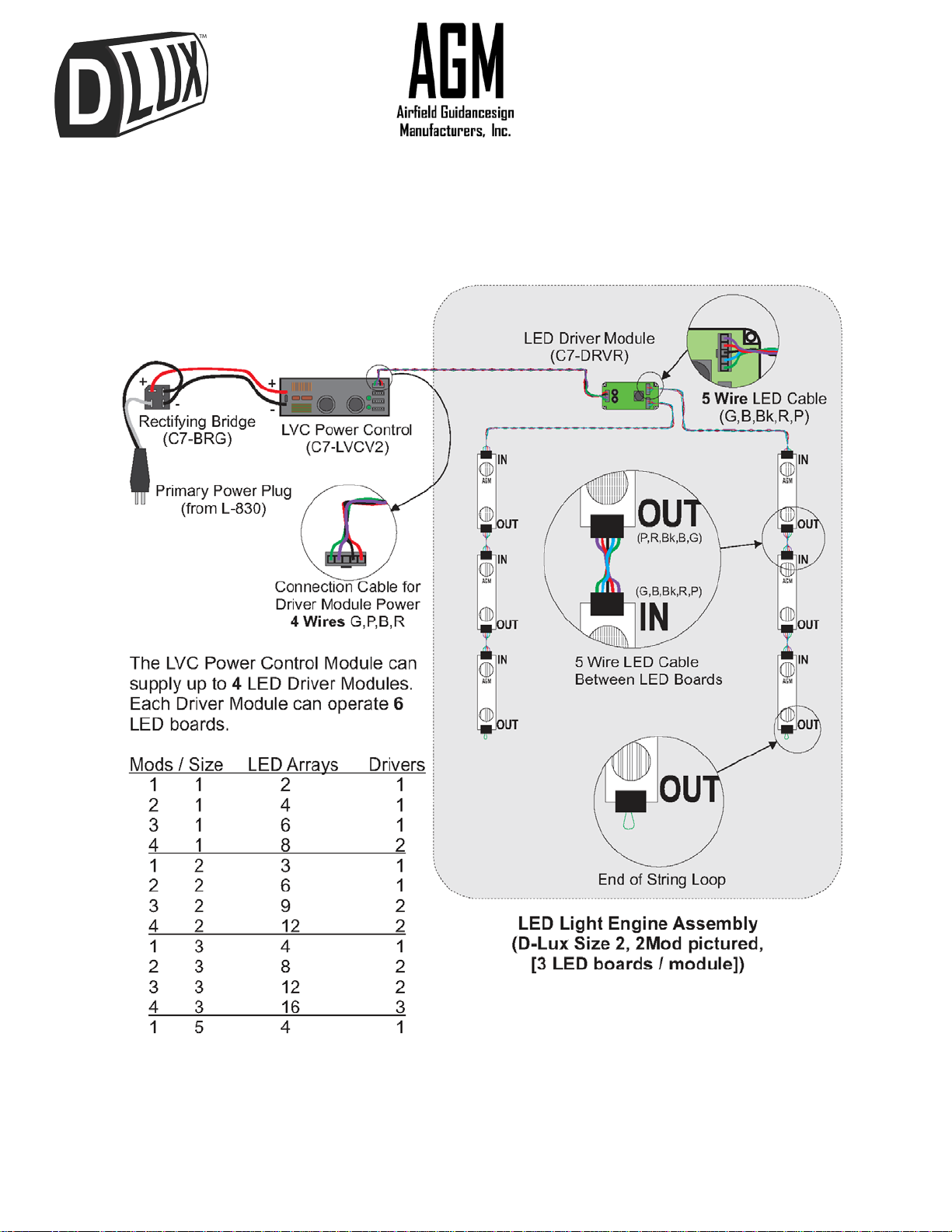
Identify the components with different type and length wire harnesses. An inventory of each kit
can be found on pages 14 to 16. Power to driver wire harnesses have 4wires and a ferrite coil at
one end, as shown on pages 5 to 8. They are already plugged into the driver modules and ready
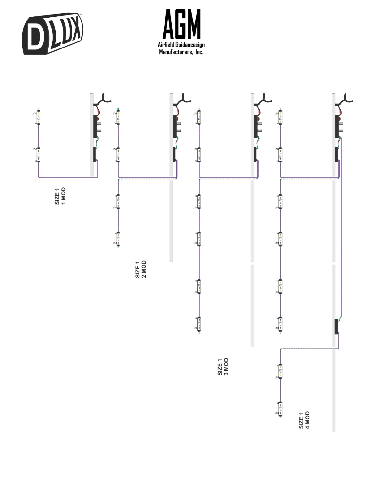
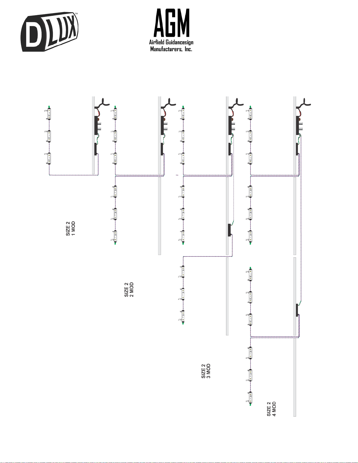
to be routed back to the power supply output. LED to LED wire harnesses have 5wires and are
plugged into the bottom of the driver modules, ready to be routed to the IN connection of an LED
board on a mounting bracket. Additional LED to LED wire harnesses may be plugged into the
OUT connection of a LED board on one mounting bracket to connect to an IN connection of an
LED board on an adjoining bracket. Mounting brackets are numbered from 1 to 4; number 1 is
closest to the power cord.
Useful tools to complete the retrofit are:
•Wire cutters & strippers;
•Drill with 9/64” bit and 5/16” bit;
•Countersink bit;
•#2 Phillips screwdriver and a deep 3/8” socket; and
•5/16” nut driver.
D-Lux Retrofit Installation
1. Make sure the circuit is turned off and locked out.
2. Remove the top of sign on the module where the power cord enters. Remove the panel on the
side that is easiest to work on (downwind). Replace the top after removing the panel (this will
maintain the width of the module while the light bar assembly is replaced).
3. Cut or disconnect the power cord as close to the existing power control module (PCM) as
possible. Leave enough slack to strip the ends and crimp on 1/4” female spade connectors.
4. Remove the existing light bar assembly from the first module where the power enters, and
install the replacement light bar assembly shipped with the retrofit kit. Cut off any old wiring
that extends into connecting modules. The replacement light bar assembly should be oriented
with the rectifying bridge closest to the power end of the sign. Mounted on the underside of the
replacement light bar assembly, the rectifying bridge is a black 1” square, 1/4” thick with 4,
1/4” spade terminals, two of which have a black and a red wire connected to the LVCV2 PCM.
If the holes on the end of the light bar do not line up directly with the holes on the castings, use
a 5/16” drill bitto run through the casting tabs to widen and align the holes. Insert the bolts and
washers, and attach the K-Lock nuts to secure the light bar assembly to the sign module.
Once secure, the top of the sign can be removed and set aside.
5. The GDT surge protector is connected to the rectifying bridge and will have two insulated 1/4”
male spade terminals open where the power cord is [to be] connected. Crimp the 1/4” female
spade connector terminals contained in the hardware kit on the ends of the power cord that
have been stripped back 1/4” from where they were cut. Connect the male terminals of the
GDT to the female terminals of the power cord.
D-Lux LED Retrofit Installation – March 2014 Page | 3