AGPS Pipe Pro User manual

Manual revision date: 8/31/22
www.CooksAGPS.com

2
Table of Contents
Welcome ..............................................................................................................................................................4
Basic Concepts...................................................................................................................................................4
How the Program Calculates Grade .......................................................................................................................4
Units of Measure ...........................................................................................................................................................5
Glossary of Terms.........................................................................................................................................................5
The Main Working Screen .............................................................................................................................7
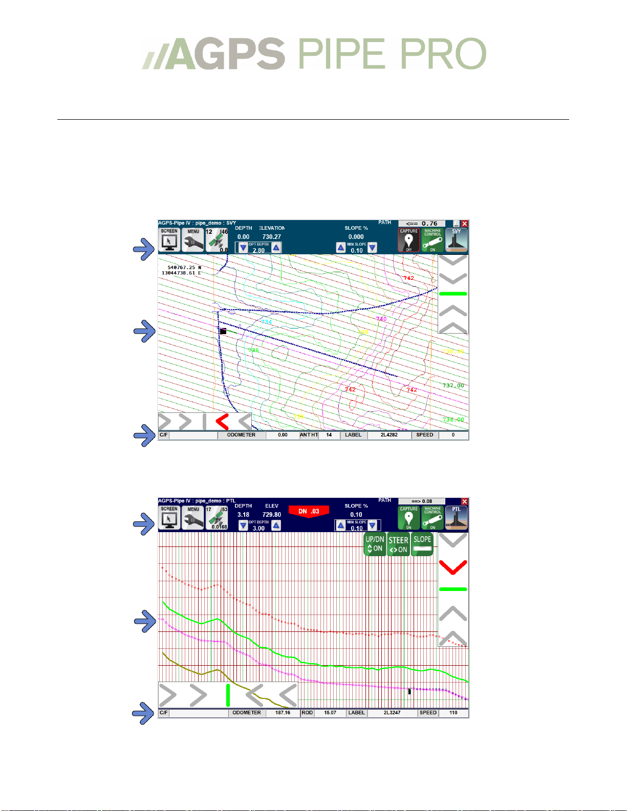
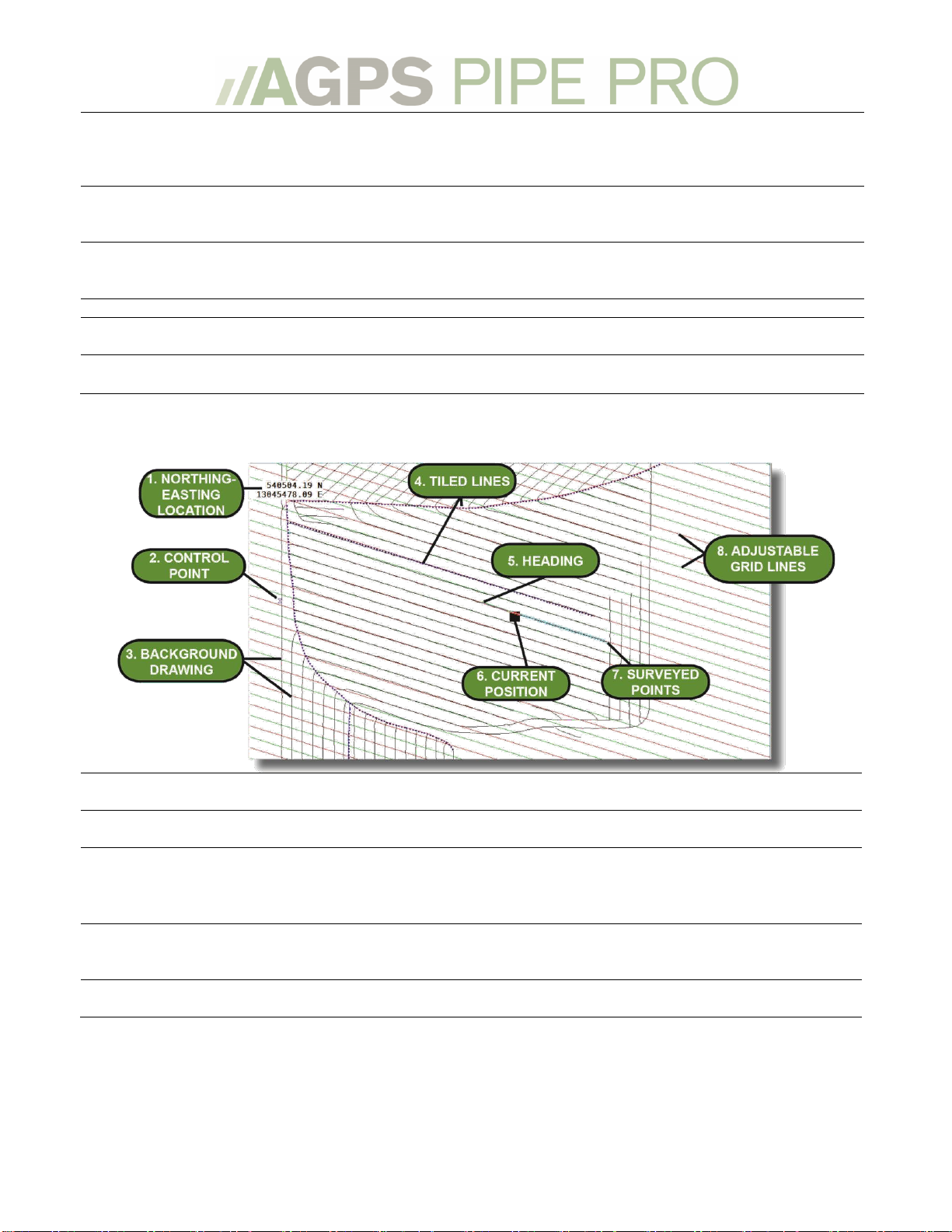
The Main Working Screen –Overhead View.......................................................................................................7
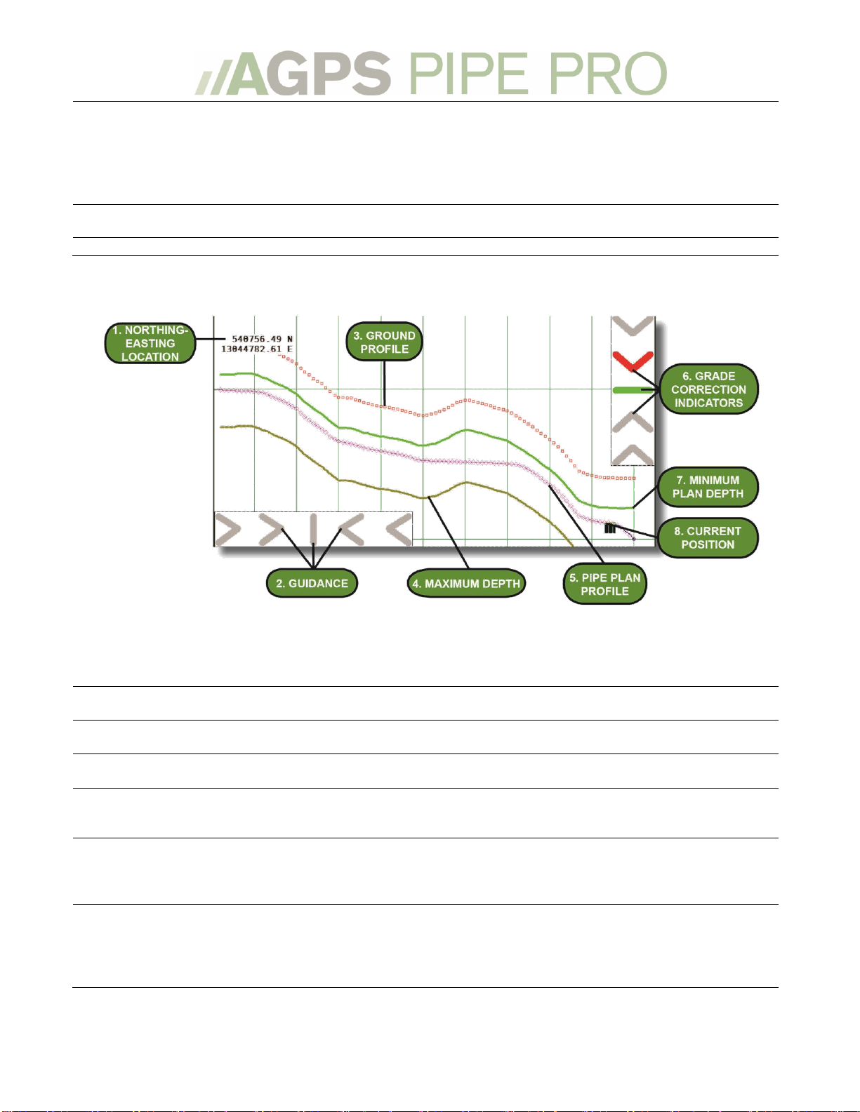
The Working Screen –Profile View........................................................................................................................7
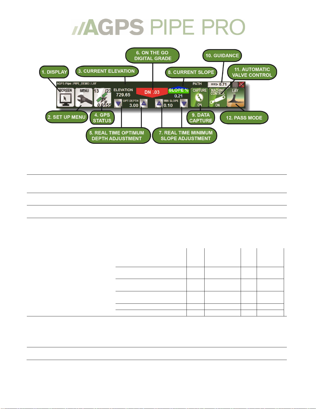
The Working Screen –Menu Bar.............................................................................................................................8
The Plot Screen –Overhead View............................................................................................................................9
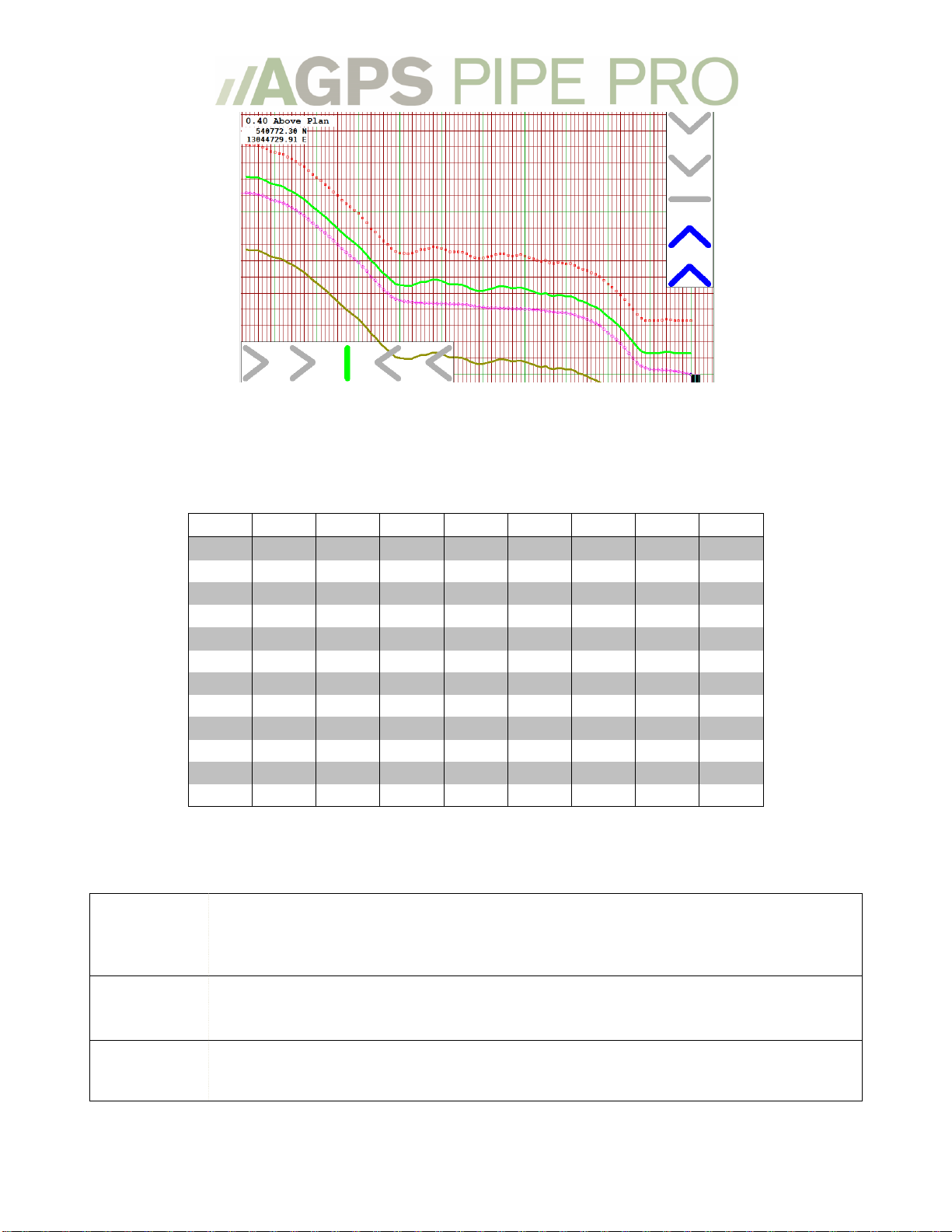
The Plot Screen –Profile View.............................................................................................................................. 10
The Working Screen –Info Bar............................................................................................................................. 11
Setting up the program................................................................................................................................ 11
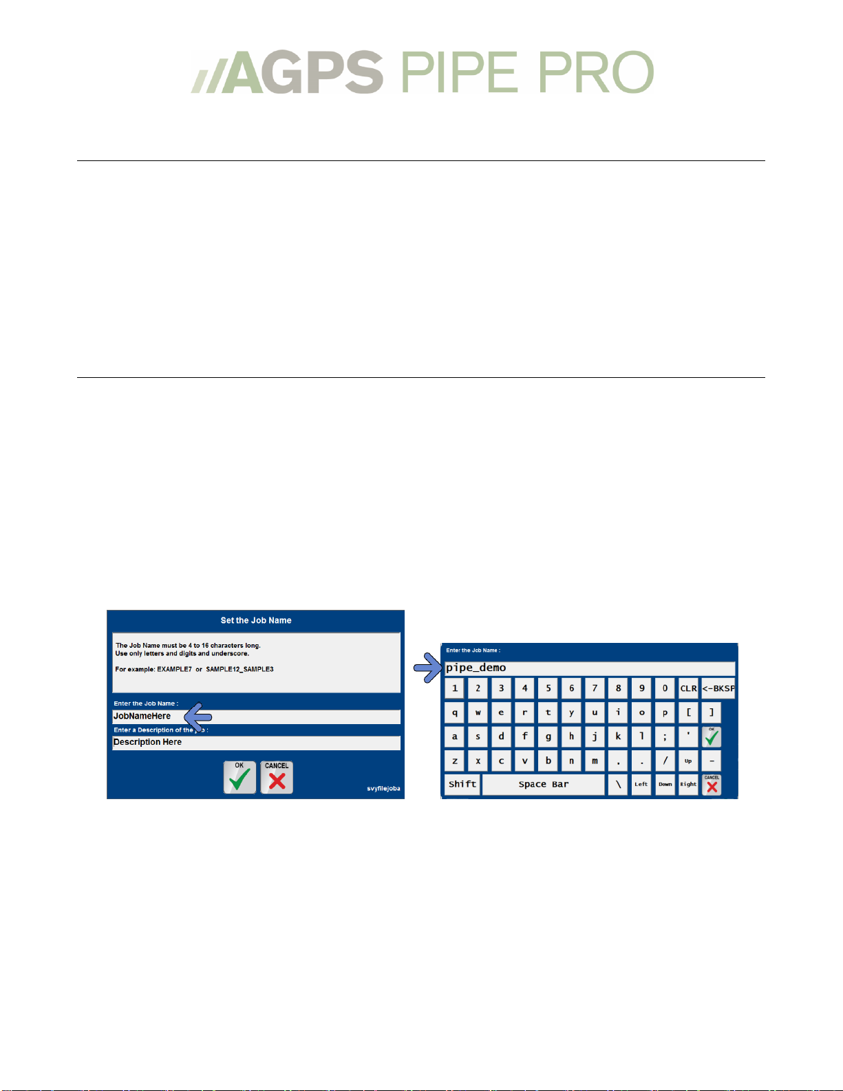
Setting up the program for the first time:......................................................................................................... 11
Starting a New Job or Restarting a Current Job, via Dashboard: .............................................................. 15
Start/Restart a Job, via menus:............................................................................................................................. 17
Working with RTK-GPS ...............................................................................................................................19
Configuring my GPS .................................................................................................................................................. 19
GPS Status..................................................................................................................................................................... 19
Troubleshooting my GPS ........................................................................................................................................ 20
Rod Length and Survey Pass Offset..................................................................................................................... 21
Rod Length.................................................................................................................................................................................21
Survey Pass Offset................................................................................................................................................................... 21
Rip-Lay Vertical Distance.....................................................................................................................................................21
Working with the Program ........................................................................................................................22
Adjusting the view..................................................................................................................................................... 22
The Buttons Menu...................................................................................................................................................................23
The Click Menu.........................................................................................................................................................................24
The Light Bars............................................................................................................................................................. 25
The Light Bar Menu................................................................................................................................................................26
The Grid ........................................................................................................................................................................ 27
Setting up the Grid..................................................................................................................................................................27
Using the Grid ...........................................................................................................................................................................29
Loading Background Images................................................................................................................................. 29
Laying Tile........................................................................................................................................................ 30
Pass Labels................................................................................................................................................................... 30
Reading a pass label ...............................................................................................................................................................30
Selecting a Pass Label............................................................................................................................................................30
Pass Types.................................................................................................................................................................... 32
Survey Pass.................................................................................................................................................................. 33
Creating a Survey Pass..........................................................................................................................................................33
Rip Pass......................................................................................................................................................................... 34
Creating a Rip Pass .................................................................................................................................................................34
Recalling a Previously Captured Survey or Rip Pass.................................................................................... 36

3
Lay-Minimum Pass.................................................................................................................................................... 37
Creating a Lay Minimum Pass............................................................................................................................................37
Topography Pass ....................................................................................................................................................... 39
Collecting a Topo Pass...........................................................................................................................................................39
Previous Topo Lay Pass........................................................................................................................................... 40
Creating a Previous Topo Lay Pass .................................................................................................................................. 40
Surfaces in Previous Topo Lay........................................................................................................................................... 42
Design Info Screen and Modifying Points in a Design .................................................................................. 42
Above Plan Commit-To Error................................................................................................................................ 44
Control Points (.ctl file) ........................................................................................................................................... 44
Collecting a Control Point ....................................................................................................................................................45
Finishing a Job ................................................................................................................................................46
Creating Reports........................................................................................................................................................ 46
Exporting Data............................................................................................................................................................ 46
Export Data Options...............................................................................................................................................................47
Menus ................................................................................................................................................................ 48
Main Menu.................................................................................................................................................................... 48
Instrument Menu....................................................................................................................................................... 49
Plot Menu...................................................................................................................................................................... 51
Survey File Menu ....................................................................................................................................................... 52
Devices Menu .............................................................................................................................................................. 53
Parameters Menu ...................................................................................................................................................... 54
Essentials Parameters menu:.............................................................................................................................................54
Advanced Parameters Menu...............................................................................................................................................55
Pass Menu..................................................................................................................................................................... 57
Miscellaneous actions.............................................................................................................................................. 58
Quit this Application................................................................................................................................................. 59
UTM Zones.................................................................................................................................................................... 60
State Plane.................................................................................................................................................................... 60

4
Welcome
Thank you for purchasing AGPS-Pipe Pro™. This manual will guide you through the setup and
running of the program.
AGPS-Pipe Pro™ provides assistance in laying drainage pipe ( or "tile" ). The program will
calculate the elevation and grade of the pipe and control the plow blade in laying the pipe.
If you have further questions, please contact your AGPS Dealer or the AGPS technical support via
Basic Concepts
AGPS-Pipe Pro™ will capture the topography of a tile line, either by surveying the line, ripping
the line or by utilizing previously captured topography, and based on that topography and on
certain parameters (like minimum-slope, minimum-depth, optimum-depth) will calculate a plan
of elevations where the pipe should be laid, show it to you and, and control the plow blade.
AGPS-Pipe Pro™ can be navigated with either the touch-screen interface or utilizing a standard
keyboard. Most of the instructions in this manual are based on utilizing the touch-screen
interface. For shortcut keys with a keyboard, see the Buttons menu on page 23.
The touch-screen interface has an on-screen keyboard function –when you need to enter text
(job name, naming a control point, etc.) simply touch where you need to enter text and the on-
screen keyboard will pop-up.
How the Program Calculates Grade
AGPS-Pipe Pro™ Designs the tile line based on what the user selects as the minimum slope and
optimum depth. The program will attempt to place the tile line at the Optimum Depth while
never violating minimum slope.

5
Units of Measure
AGPS-Pipe Pro™ can be set to work in Feet (International); Feet (U.S. Survey); or Meters. A
typical user in the United States will choose Feet (U.S. Survey). For both Feet (International) and
Feet (U.S. Survey) will be calculated and displayed in tenths of feet, so that 6.5’ is the same as 6’6”.
Inches and Eighths to Decimals of a Foot
In.
0
1/8
1/4
3/8
1/2
5/8
3/4
7/8
0
.00
.01
.02
.03
.04
.05
.06
.07
1
.08
.09
.10
.11
.12
.14
.15
.16
2
.17
.18
.19
.20
.21
.22
.23
.24
3
.25
.26
.27
.28
.29
.30
.31
.32
4
.33
.34
.35
.36
.38
.39
.40
.41
5
.42
.43
.44
.45
.46
.47
.48
.49
6
.50
.51
.52
.53
.54
.55
.56
.57
7
.58
.59
.60
.61
.62
.63
.64
.65
8
.67
.68
.69
.70
.71
.72
.73
.74
9
.75
.76
.77
.78
.79
.80
.81
.82
10
.83
.84
.85
.86
.88
.89
.90
.91
11
.92
.93
.94
.95
.96
.97
.98
.99
Example: 3-½” = .29”
Glossary of Terms
Capture
Auto Capture: Automatically captures a data points after user set interval (typically 10 feet) has
been traveled. This distance uses both horizontal and vertical measurement. Toggling the Auto
Capture button on and off will capture a single point at your current location. Toggled ON/OFF
by keyboard spacebar.
Machine
Control
In the program the term Machine Control refers to the automatic control of the blade. The
control can be toggled by keyboard 0. There are other places in the program that blade used in
a sentence will have different context.
Control
point
(.ctl file)
Sometimes called a benchmark, this point is a known world feature in which coordinates are
also known. Control points are important to make your coordinates match those used earlier.
See Control Points on page 44.

6
Data folder
All job file data opened and saved by the program is stored by default in C:\amw\data\
Device
Other forms: Device Menu, External Device, Control Device, etc. The Device refers to interface
device that operates the automatic blade control, such as a DAC-7000/DAC-8000™ or a
LaserTech™ 308 control module.
Instrument
Other forms: Instrument Menu, Measuring Instrument, Read Instrument, etc. The instrument is
the positional equipment. Although typically a GPS, there are many other types, and
combinations of multiple instruments. See Working with RTK-GPS on page 19.
Local Point
A NEZ coordinate system that uses “fake” coordinates, meaning they are not consistent with
State Plane or UTM. An example of this is program default “ptafake 5000 2000 100”.
NEZ
Abbreviation for Northing(N) Easting(E) Elevation (Z). Coordinates are always in NEZ. NEZ
coordinates are in Feet (or meters if selected) rather than Latitude Longitude and Altitude.
.nez file
A file that uses the following columns: “Name Northing(N) Easting(E) Elevation(Z)
Description”. (Description is optional)
Path
The line (curved or straight) you wish to follow. You can set a path by touching the path you
wish to follow on the Plot. See also: Plot
Plot
Other forms: Plot Menu, Plot Window, etc. The Plot is the lower screen that the field is
graphically drawn in. Any options to adjust a feature drawn here are found in the Plot Menu.
See Plot Menu on page 51.
Quick setup
mode
A toggled option to automatically start this application instead of going to the Main menu to
select an application.
Rod (length)
The distance from the reading point (on the GPS antenna) to the blade or ground. The term
Antenna Height is also used interchangeably. See Rod Length on page 21.
State Plane
A NEZ coordinate system with zones designed for a particular US State. Every State has one or
more zones. See UTM and State Plane on page 60.
Odometer
The current distance from the start of the selected Path.
Status (GPS)
Shown on the working screen to describe GPS status and other related messages. Shows
something like “ok: 19 41.1 /53” Where 19=satellites 4=datatype 1.1=precision and
/53=read counter.
Use the table below to evaluate the data type and precision meaning for your GPS.
RTK
Fixed
RTK Float
No RTK
base
Precision
GGA (Most manufacturers)
4
5
1
HDOP
John Deere™
4
3=extend
5=float.
1
HDOP
NovAtel™ (Raven™/AgLeader™)
50
49/48/34/17
16
Alt. Std.
Deviation
Topcon™ (Javad™ GGA)
4
5
1
HDOP
Trimble™ (GGK)
3
2
1
PDOP
Survey File
(.svy)
This file will contain all data points captured. Also, "Location Instrument" setup information
and other relevant information are logged to this file. Points from this file will be displayed on
your plot window as dots. The Survey File Menu includes options to modify this file.
UTM
A NEZ coordinate system with zones designed on Longitude lines. The program can
automatically detect your UTM zone. See UTM and State Plane on page 60

7
The Main Working Screen
The AGPS-Pipe Pro™ working screen is divided into three sections:
1. The Top Menu Bar on page 8
2. The Middle Plot Screen, with an Overhead View on page 9 and a Profile View on page 10
3. The Bottom Info Bar on page 11
The Main Working Screen –Overhead View
The Working Screen –Profile View
Menu Bar
Plot screen
Info Bar
Menu Bar
Info Bar
Plot screen

8
The Working Screen –Menu Bar
The majority of icons in the Menu Bar are touch active. Several also have a secondary function
that can be accessed by pressing and holding the icon for 3 seconds.
The Menu Bar will change color depending on the Current Pass Mode. See Pass Menu on page 32.
1.
Display
Touch this icon to drop down the display menu where you can adjust the
zoom level, scroll around the screen or adjust the grid. See Adjusting the
View on page 22.
2.
Set Up Menu
Touch this icon to start a new job, switch to a different job or adjust your
parameters. See Setting up the Program on page 11.
3.
Current Elevation
The current elevation of the plow blade. Can be in meters, feet-international
or feet-survey. See Setting up the Program on page 11.
4.
GPS Status
Icon showing current GPS status. Must be green for the program to work.
Touch to access the Instrument Menu see Instrument Menu on page 49.
The following menu shows the data types for often used RTK-GPS systems.
Shows something like “ok: 19 4 1.1 /53” Where 19=satellites 4=datatype
1.1=precision and /53=read counter.
RTK
Fixed
RTK Float
No
RTK
base
Precision
GGA (Most manufacturers)
4
5
1
HDOP
John Deere™
4
3=extend
5=float.
1
HDOP
NovAtel™
(Raven™/AgLeader™)
50
49/48/34/17
16
Alt. Std.
Deviation
Topcon™ (Javad™ GGA)
4
5
1
HDOP
Trimble™ (GGK)
3
2
1
PDOP
5.
Optimum Depth Adjustment
Adjusts the Optimum Depth of the tile line. Please note that AGPS-Pipe Pro™
will redesign the tile line from your current location, removing previously
laid tile points for that line from the screen. The amount the Optimum
Depth Adjustment buttons adjust can be set in the Parameters Menu on page
54.
6.
Digital Grade
Visual real-time indicator of the position of the plow in relation to designed
grade.

9
7.
Minimum Slope Adjustment
Adjusts the Minimum Slope of the tile line. Please note that AGPS-Pipe Pro™
will redesign the tile line from your current location, removing previously
laid tile points for that line from the screen. The amount the Minimum Slope
Adjustment buttons adjust can be set in the Parameters Menu on page 54.
8.
Current Slope
Slope of the design or ground at the current point. When using a slope
sensor on the plow, there will be arrows indicating if the back of the boot
needs to go up or down to match desired slope.
9.
Data Capture
Auto Capture icon. Green for On, black/red for Off. When on, AGPS-Pipe
Pro™ will capture a point after a preset distance (default is 10 feet). Adjust
this distance in the Parameters Menu on page 54.
10.
Guidance
Distance from the survey path.
11.
Valve Control
Automatic control of the machine. Green for On, black/red for Off. Press
and Hold to access the Devices (machine control menu).
12.
Pass Mode
Current Pass Mode. Press and Hold to change pass mode. See Pass Types on
page 32.
The Plot Screen –Overhead View
1.
Northing-Easting Location
Real time display of your current location in Northing and Easting in
Feet (or Meters).
2.
Control Point
Visual indication of the location of a Control Point. See Control Points on
page 44.
3.
Background Drawing
An example of lines in a Background Drawing. A Background Drawing
can be built and imported from multiple design programs such as
Surfer™, Ag Data Mapping Solutions™, Auto-Cad™, Farm Works™,
AGREM™, among others. See Loading Background Images on page 29
4.
Tile Lines
Previously Tiled lines appear as dark blue dotted lines. If you label your
lines you can also have the main lines appear as magenta lines, see
Previous Topo Lay on page 40.
5.
Heading
Green line that shows real time heading of the current position. The
heading is drawn from the upper left-hand corner of the icon.

10
6.
Current Position
Visual real-time indicator of the position of the plow. The upper left-
hand corner of the icon is considered the ‘true’ position of the plow. You
can set a ‘fake’ position by touching the screen and either setting where
you touched as the fake position or by ‘snapping’ to a point and setting
that as the ‘fake’ position. ‘Fake’ positions are useful in rotating the grid
around a point and in setting Previous Topo Lay points.
7.
Surveyed Points
As you survey or rip, a light blue dotted line will be drawn.
8.
Adjustable Grid Lines
Grid lines to aid in surveying/tiling. See The Grid Menu on page 27
The Plot Screen –Profile View
*Important Note: In the Profile View the X and Y (elevation and distance) are NOT drawn to the
same scale in order for both the horizontal and vertical lines to fit on the screen. This will cause
some lines to seem more steep over distance than they actually are and vice versa.
1.
Northing-Easting Location
Real time display of your current location in Northing and Easting in
Survey Feet.
2.
Guidance
Real time guidance light bar. Visual indicator of how far off the original
survey pass you are.
3.
Ground Profile
Red data points showing the relative elevation of your original survey
pass.
4.
Maximum Depth
The Maximum Depth of the tile line. AGPS-Pipe Pro™ will not allow the
pipe plan to go below this line. It can be adjusted in the Parameters
Menu, on page 54.
5.
Pipe Plan Profile
Where AGPS-Pipe Pro™has calculated the tile should be placed based on
the topography of the line and the Parameters. AGPS-Pipe Pro™
attempts to place the tile at the Optimum Depth with never violating the
Minimum Slope.
6.
Grade Correction Indicators
Real time Elevation guidance light bar. Visual indicator of how far off the
Pipe Plan Profile the plow blade is. Also functions as a blade offset
button. By pressing the up arrow chevrons the program will offset the
plow blade a set amount above plan. See Light Bars on page 25 for more
information.

11
7.
Minimum Plan Depth
Visual indication of a desired minimum depth. AGPS-Pipe Pro™ MIGHT
violate minimum depth in order to keep the Pipe Plan Profile from
violating Minimum Slope.
8.
Current Position
Visual real-time indicator of the vertical position of the plow blade. The
upper left-hand corner of the icon is considered the ‘true’ position of the
blade.
The Working Screen –Info Bar
1.
Cut/Fill
The current amount above or below grade AGPS-Pipe Pro™ is laying tile at. Touch to set a
different Cut/Fill.
2.
Odometer
Real time odometer of the distance of the current pass
3.
Rod Length
The Current Rod Length/antenna height. The rod length is defined as the distance from the
measuring instrument (i.e. GPS globe) and the tip of the plow blade. See Rod Length on
page 21
4.
Pass Label
Current pass label. Touch to choose a different label. See Pass Labels on page 30.
5.
Speed
Current speed in feet or meters per minute
Setting up the program
Setting up the program for the first time:
Follow these procedures for the first time you set up AGPS-Pipe Pro™. If you have previously set
up the program or an AGPS-Pipe Pro™ Technician has completed these setup procedures, please
skip to Starting a New Job or Restarting a Current Job, via Dashboard on page 15
Start AGPS-Pipe Pro™
If the program does not load on
computer startup, locate and double
tap the Start the AGPS icon on the
desktop. A starting screen will briefly
appear.

12
Enter the code AGPS. Touch the
entry field to pull up a touch screen
keypad.
Select the unit of measure (typically
Feet U.S. Survey for U.S. users).
Select AGPS-Pipe Pro™from
the Dashboard’s “Program”
Dropdown menu.
Press Start button.
Agree to the Disclaimer, you
must do this every time you
start AGPS-Pipe Pro™
Press Menu
Select Setup Program (many
questions).
Select None, Make a New Job.
Enter the name of the job (i.e.
the name of the field or the name of
the customer). You may also enter a
description of the job.
Setup your control points. If
you have no control point for this job,
select Quit, No (further) Changes.
If you have control points (see Control
Points on page 44) you can choose to
edit the control point file and add
the point.

13
Choose the Instrument (GPS).
The GPS instrument must be
configured to output the correct
message type. Cousult the GPS
manufacturer for specifics.
Then Choose the Com Port the GPS is
outputting messages to.
Select the Normal Rod Length.
The Normal Rod is the typical rod
length.
To add your rod length, select Add1.
Select Rod Tip Corrections. If
you have a slope sensor, select it here.
Without a slope sensor select ‘Cross
and Forward Slope Only’. The
program will attempt to
mathematically compensate for steep
grades. (You must set the correct Rod
Length for this to work properly)
Set the Location-Instrument
Position. If you use UTM, select
UTM 0 point. If you do not know the
UTM zone, select Unknown, Calculate.
If you use State Plane, select State
Plane 0 point and select the State
Plane.
or
Bitmap control option or
Background Drawing
You can load a bitmap image for a
background drawing. See Loading
Background Images on page 29.
Survey load and Pipe-
Previous
You will see two status screens that
tell you if any points were loaded
(new jobs should have 0 points
loaded).
Select OK on each screen.

14
Parameters Menu
Adjust the parameters to your
preferred settings. Select an option to
see a more detailed description.
Be sure to adjust the Survey-Pass
offest. This is how high the blade is
held above the ground when you
survey. You must survey with the
blade in the same place each time
(typically all the way up).
Also adjust the Blade-length,
Optimum Depth and Maximum
Depth.
For more details, reference the section
on the Parameters Menu on page 54
Device Menu. Select the type of
auto-blade controller you have.
Contact the Auto-Blade control
manufactuerer for more details on
setting up the device.
Typical controllers are the
LaserTech™ with MultiPlexor,
DAC 7000™ or Bron Can-Bus™
control. Then select the Com
port the controller is plugged
into.
The Main Working Screen will
appear: You should be able to
begin working.
TroubleShooting Tips:
I finished the setup, but the screen
flashes red
This is typically related to the GPS signal. See Troubleshooting My GPS on
page 20.
I missed/mess up a step
You can go through the setup process again from the Main Menu. Press the
Menu Icon on the Working Screen.

15
Starting a New Job or Restarting a Current Job, via Dashboard:
Follow these procedures to each time to start AGPS-Pipe Pro™.
Start AGPS-Pipe Pro™
If the program does not load on
computer startup, locate & double tap
the Start the AGPS icon on the desktop.
A starting screen will briefly appear.
①Program
Select a program to open. It should say AGPS-Pipe Pro.
Press the down arrow to show/select other programs purchased.
②Job Name
Select a Job Name from the dropdown list.
For a New Job: Select None, Make a New Job, at the top of the list.
❶
❷
❸
❹
❺
❻
❼❽ ❾ ❿ ⓫ ⓬⓭ ⓮ ⓯
⓰

16
③Setup Type
- If you have no control point, like starting
a new job, Select UTM 0 point or State
Plane 0 point. See Zones on the last 2
pages of this manual.
- If you have a control point, Select UTM 1
point or State Plane 1 point.
- If you are re-setting up on the same job
and nothing has changed, select: Use
Previous Setup.
*2 Local Points, 1 Local Point, and TM Grid should only be used when
trying to use surveyor’s coordinates.
④Region
(also called zone) displays the region selected in #3 above.
⑤ Antenna Height
Also called Rod Length, is the distance from the GPS Antenna to the tip
of the blade on a plow or the bottom of the wheel on a trencher.
⑥ GPS Instrument
Displays the type of instrument, or simulator. This cannot be changed
from the Dashboard, see Instrument Menu on page 49
⑦ GPS status
Displays the same information as on working screen, on page 8.
If there is an error, that is labeled below the icon.
Touching the icon will open the “Control the Instrument” menu with
some settings options that vary with each type of instrument.
⑧Check setup
Not currently implemented.
⑨User Pref
Preferences menu that allows customization of menu colors/font, as
well as a few menu behavior settings.
⑩Job
Management
Various tabs to make changes to
control points, design surface,
background image, & more.
“Data Backup”tab allows
copying all files from \data
folder to another folder on
start/exit. Useful for cloud
backup.
⑪Utilities
Miscellaneous Utilities.
Change Distance units.
Security Menu (Show or Set Capabilities)
⑫Help
Not currently implemented.
⑬Shutdown
Computer
Close the program, and safely Shutdown the Computer. (every 10th time
will ask if you want to save a backup of program setting database)
⑭Exit
Exit the program, back to Windows desktop
⑮Start
Start the program, with the chosen settings.
⑯Version
Displays the version of the software currently installed.

17
Start/Restart a Job, via menus:
Follow these procedures to use the Legacy method to start AGPS-Pipe Pro™.
1. Start AGPS-Pipe Pro™
If the program does not load on
computer startup, locate and double
tap the Start AGPS icon on the desktop.
A starting screen will briefly appear.
2. Select AGPS-Pipe Pro™from
the Dashboard’s “Program”
Dropdown menu.
3. Press Start button.
4. From the Working Screen,
Press Menu
5. Select Setup Program
(Different Job) for a new job or
Resetup Program for the job
you’re currently working on
(skip to step 7)
6. For a New Job:
Select None, Make a New Job.
Enter the name of the job
(i.e. the name of the field or the name
of the customer). You may also enter a
description of the job.
7. Setup the Location
Instrument
- If you have a control point, Select
UTM 1 point or State Plane 1 point.
- If no control point, Select UTM 0
point or State Plane 0 point
- If you are re-setting up a job and
nothing has changed, select
Do nothing now, keep existing
setup and skip to step 11.

18
8. Set the Location-
Instrument Position.
Select your UTM Zone or your State
Plane Region. If you do not have a
control point, skip to step 11.
or
9. Load a Control Point
- Select the Rod Length you are going
to use to read the instrument
- Select the Control Point you want to
read (if you have a control point but it
is not loaded into the program, choose
None of These, Change the File)
10. Read the Instrument
- Read the Instrument after you have
set the pause amount and # of tries
(see Control Points on page 44 for
more detail)
- Check the Setup: The program will
tell you how many reads were
successful and what the averages
were. Press OK
11. Survey load and Pipe-
Previous
You will see two status screens that
tell you if any points were loaded
(new jobs should have 0 points
loaded). Select OK on each screen.
The Main Working Screen will
appear: You should be able to
begin working.

19
Working with RTK-GPS
AGPS-Pipe Pro™ is designed to be used with most high-grade RTK-GPS systems. The accuracy of
AGPS-Pipe Pro™ is directly related to the accuracy of the RTK-GPS system that you utilize. Not all
RTK-GPS systems are the same and offer the same accuracy and repeatability. Contact your
AGPS-Pipe Pro™ dealer for recommendations on current RTK-GPS systems.
Configuring my GPS
The following tables list the output options that should be enabled on common brands of GPS
systems. If your GPS system does not appear on this list, please contact your AGPS-Pipe Pro™
Dealer or Technician for setup details. The Hz (update) rate and Baud rate must also be set in
the AGPS-Pipe Pro™ program. To set these, press the Menu icon, select Instrument Menu,
Control the Instrument and adjust both the Hz and Baud rates.
Ashtech
TopCon
JD ITC
JD 3000
Msg type
GGA
GGA
GGA
GGA
HZ rate
10
10
5
10
BAUD rate
57600
57600
38400
57600
NovAtel
300/ 410
Trimble
(older)
Trimble
(newer)
Msg type
BestPos
BestPos
GGK
GGA
HZ rate
10
10
10 & ASAP
10
BAUD rate
57600
57600
38400
57600
GPS Status
Each individual RTK-GPS system will have it’s own standard for being in ‘fix’ and the type of
data/degree of precision it returns.
Common GPS Systems data:
RTK Fixed
RTK Float
No RTK base
Precision
GGA (Most manufacturers)
4
5
1
HDOP
John Deere™
4
3=extend
5=float.
1
HDOP
NovAtel™ (Raven™/AgLeader™)
50
49/48/34/17
16
Alt. Std. Deviation
Topcon™ (Javad™ GGA)
4
5
1
HDOP
Trimble™ (GGK)
3
2
1
PDOP
A Note on ‘DOP’:
HDOP, VDOP, and PDOP are respectively Horizontal, Vertical, and Positional (3D) Dilution of
Precision. The precision of multiple satellites in view of a receiver combine according to the
relative position of the satellites to determine the level of precision in each dimension of the
receiver measurement. When visible GPS satellites are close together in the sky, the geometry is
said to be weak and the DOP value is high; when far apart, the geometry is strong and the DOP
value is low. Thus a low DOP value represents a better GPS positional precision due to the wider
angular separation between the satellites used to calculate a GPS unit's position. Other factors
that can increase the effective DOP are obstructions such as nearby mountains or buildings.

20
DOP
Value
Rating
Description
<1
Ideal
This is the highest possible confidence level to be used for applications demanding the
highest possible precision at all times.
1-2
Excellent
At this confidence level, positional measurements are considered accurate enough to
meet all but the most sensitive applications.
2-3
Good
Represents a level that marks the minimum appropriate for making business decisions.
Positional measurements could be used to make reliable in-route navigation
suggestions to the user.
>3
Poor
Should be used only to indicate a very rough estimate of the current location.
Troubleshooting my GPS
TroubleShooting Tips:
COM Port already in use
The Communications Port that the GPS is plugged into is being used by
another program or is closed for some reason.
1. Verify that the GPS is plugged into the correct COM port.
2. Unplug the GPS from the COM port, power-cycling the computer,
restarting AGPS-Pipe Pro™ and then re-plugging the GPS.
No GPS Data
The GPS is sending no signal, or the computer is receiving nothing.
1. Verify the GPS is powered on.
2. Verify the GPS is plugged into the COM port.
3. Verify the GPS is sending the configured correctly as described in
Configuring my GPS on the previous page.
Bad Data
The GPS is sending bad or incorrect data
1. Verify the GPS is plugged into the correct COM port
2. Verify the GPS is configured correctly
3. Verify AGPS-Pipe Pro™ is configured to the correct instrument and
to the correct incoming Baud and Update rate.
Bad Position Type X (#)
Where X is the type, see table
under "GPS Status"
The GPS is not seeing the base station
1. Verify the base station is powered on.
2. Verify the base station is within the manufacturer guidelines for
distance.
3. Verify the rover is configured to read the base station.
4. Double check radio antennas and cable connections.
Goes in and out of fix
The GPS going in and out of fix can be a symptom of several different
problems:
Poor line-of-site with the base.
Poor Satellite visibility.
Damaged GPS Rover Antenna.
Table of contents
Popular Industrial Equipment manuals by other brands

Nikon
Nikon XT V 160 Operator's manual

Manntek
Manntek DDC Service instruction

Astronergy
Astronergy Crystalline Silicon PV installation manual

PCB Piezotronics
PCB Piezotronics M261B03 Installation and operating manual

BVA Hydraulics
BVA Hydraulics HG15002 instruction manual

Eaton
Eaton PKE65/AK/XTU-65-SP Instruction leaflet