Grunbeck GENO-WT 146 User manual

We understand water.
Accessories | Heat exchanger
GENO-WT 146/210
Operation manual

Central Contact
Germany
Sales
Phone +49 (0)9074 41-0
Service
Phone +49 (0)9074 41-333
Availability
Monday to Thursday
7:00 am - 6:00 pm
Friday
7:00 am - 4:00 pm
Subject to technical modifications.
© by Grünbeck Wasseraufbereitung GmbH
Original operation manual
Edition: Juli 2021
Order no.: 100199150000_en_005

Table of contents
3 | 56
Table of contents
1Introduction ..................................... 5
1.1 Validity of the manual ...................... 5
1.2 Other applicable documents ............ 5
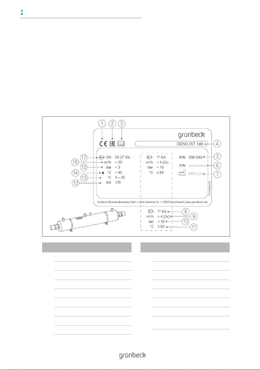
1.3 Product identification ....................... 6
1.4 Symbols used .................................. 7
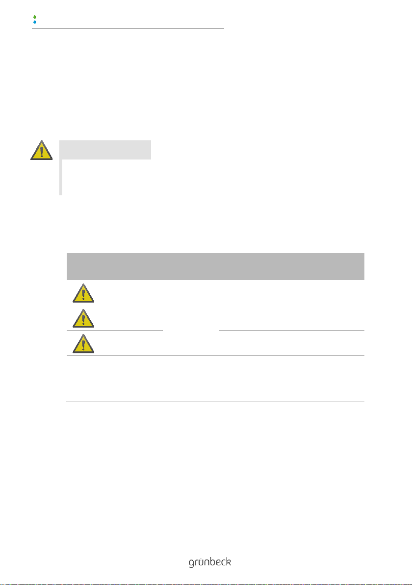
1.5 Depiction of warnings ...................... 8
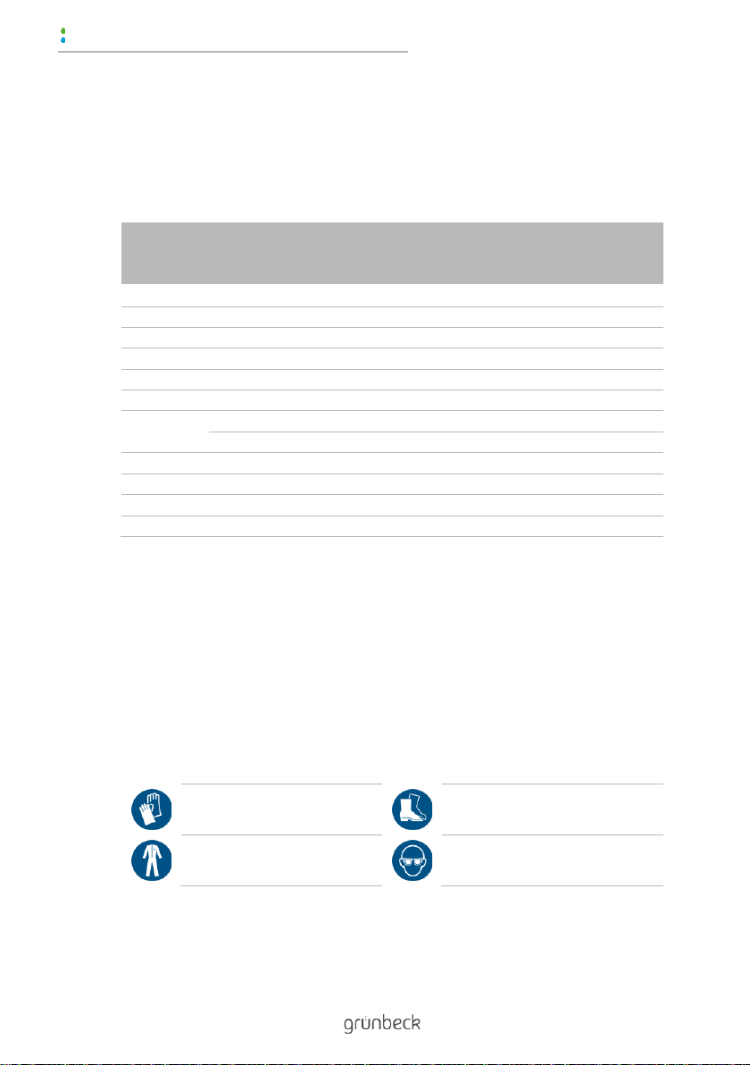
1.6 Requirements for personnel ............ 9
2Safety ............................................. 11
2.1 Safety measures............................ 11
2.2 Product-specific safety
instructions..................................... 13
2.3 Conduct in an emergency.............. 14
3Product description ...................... 15
3.1 Intended use.................................. 15
3.2 Product components...................... 16
3.3 Accessories ................................... 17
4Transport and storage.................. 18
4.1 Dispatch/delivery/packaging .......... 18
4.2 Transport ....................................... 18
4.3 Storage .......................................... 18
5Installation ..................................... 19
5.1 Requirements with regard to the
installation site ............................... 23
5.2 Checking the scope of supply........ 24
5.3 Installing the heat exchanger......... 25
6Start-up .......................................... 31
6.1 Venting the system/checking for
leaks .............................................. 32
6.2 Checking the system function........ 33
6.3 Handing over the product to the
owner/user..................................... 33
7Operation/handling....................... 34
8Maintenance and repair................ 35
8.1 Cleaning ........................................ 36
8.2 Intervals ......................................... 36
8.3 Inspection ...................................... 37
8.4 Maintenance .................................. 38
8.5 Spare parts .................................... 40
8.6 Wearing parts ................................ 40
9Fault ............................................... 41
9.1 Observations ................................. 41
10 Shut down...................................... 42
10.1 Temporary standstill ...................... 42
10.2 Restart ........................................... 42
11 Dismantling and disposal ............ 43
11.1 Dismantling.................................... 43
11.2 Disposal......................................... 44
12 Technical specifications .............. 45

Introduction
5 | 56
BA_100199150000_en_005_GENO-WT 146_210.docx
1 Introduction
This manual is intended for owners/operating companies, operators,
users as well as qualified specialists and ensures the safe and effi-
cient handling of the product. The manual is an integral part of the
product.
►Carefully read this manual and the instructions contained
within it on the components before you operate your product.
►Adhere to all safety instructions and instructions for action.
►Keep this instruction and all other applicable documents, so
that they are available when needed.
Illustrations in this manual are for basic understanding and may dif-
fer from the actual version.
1.1 Validity of the manual
●Heat exchanger GENO-WT 146
●Heat exchanger GENO-WT 210
●Special versions which essentially correspond to the indicated
standard products.
1.2 Other applicable documents
●Instructions for components from other manufacturers

Introduction
6 | 56
BA_100199150000_en_005_GENO-WT 146_210.docx
1.3 Product identification
You can identify your product by means of the product designation
and the order number on the type plate.
►Check whether the products indicated in chapter 1.1 corre-
spond to your product.
The type plate is located on the housing.
Designation
1
CE mark
2
EAC test mark
3
Observe operation manual
4
Product designation
5
Order no.
6
Serial no.
7
Date of manufacture
8
Heating connection
9
Heating flow rate
Designation
10
Heating pressure
11
Heating flow temperature
12
Heat transfer power
13
Ambient temperature
14
Water temperature
15
Swimming pool pressure
16
Swimming pool flow rate
17
Nominal connection diameter
on the heat exchanger

Introduction
7 | 56
BA_100199150000_en_005_GENO-WT 146_210.docx
1.4 Symbols used
Symbol
Meaning
Danger and risk
Important information or prerequisite
Useful information or tip
Written documentation required
Reference to further documents
Work that is only allowed to be carried out by qualified specialists
Work that is only allowed to be carried out by qualified electricians
Work that is only allowed to be carried out by technical service per-
sonnel

Introduction
8 | 56
BA_100199150000_en_005_GENO-WT 146_210.docx
1.5 Depiction of warnings
This manual contains information that you must comply with for your
personal safety. The information is marked with a warning sign and
has the following structure:
1.5.1.1
1.5.1.2 SIGNAL WORD
1.5.1.3 Type and source of danger
1.5.1.4
●Possible consequences
►Preventive measures
The following signal words are defined depending on the degree of
danger and may be used in this document:
Warning sign and sig-
nal word
Consequences when disregarding the infor-
mation/instructions
DANGER
Personal in-
jury
Death or serious injuries
WARNING
Possible death or serious injuries
CAUTION
Possible moderate or minor injuries
NOTE
Damage to
property
Possible damage to components, the
product and/or its functions, or any-
thing in its vicinity

Introduction
9 | 56
BA_100199150000_en_005_GENO-WT 146_210.docx
1.6 Requirements for personnel
During the individual life cycle phases of the product, different peo-
ple carry out work tasks on the product. The work tasks require dif-
ferent qualifications.
1.6.1 Qualification of personnel
Personnel
Prerequisites
Operator/user
•No special expertise
•Knowledge of the tasks assigned
•Knowledge of possible dangers in the case of incor-
rect behaviour
•Knowledge of the necessary protective equipment
and protective measures
•Knowledge of residual risks
Owner/operating com-
pany
•Product-specific expertise
•Knowledge of statutory regulations for safety and
accident prevention
Qualified specialist
•Electrical engineering
•Sanitary engineering
(SHK)
•Transport
•Professional training
•Knowledge of relevant standards and regulations
•Knowledge of detection and prevention of possible
risks
•Knowledge of statutory regulations on accident pre-
vention
Technical service
(Grünbeck's technical
service/authorised ser-
vice company)
•Extended product-specific expertise
•Trained by Grünbeck

Introduction
10 | 56
BA_100199150000_en_005_GENO-WT 146_210.docx
1.6.2 Authorisations of personnel
The following table describes which activities are allowed to be per-
formed by whom.
Opera-
tor/user
Owner/op-
erating
company
Qualified
special-
ist
Tech-
nical ser-
vice
Transport and storage
X
X
Installation and mounting
X
X
Start-up
X
X
Operation and handling
X
X
X
X
Cleaning
X
X
X
X
Inspection
X
X
X
X
Mainte-
nance
semi-annually
X
X
Annually
X
X
Troubleshooting
X
X
X
Repair
X
X
Shutdown and restart
X
X
Dismantling and disposal
X
X
1.6.3 Personal protective equipment
►As an owner/operating company, ensure that the required
personal protective equipment is available.
The following components fall under the heading of personal protec-
tive equipment (PPE):
Protective gloves
Protective footwear
Protective overall
Protective goggles

Safety
11 | 56
BA_100199150000_en_005_GENO-WT 146_210.docx
2 Safety
2.1 Safety measures
●Only operate your product if all components are installed
properly.
●Adhere to the applicable local guidelines on drinking water
protection, accident prevention and occupational safety.
●Do not make any changes, conversions, extensions or pro-
gram modifications to your product.
●Only use genuine spare parts for maintenance or repair.
●Keep the premises locked to prevent unauthorised access
and to protect endangered/non-instructed people from resid-
ual risks.
●Observe the maintenance intervals (refer to chapter 8.2).
2.1.1 Mechanical dangers
●Safety devices must never be removed, bridged, or otherwise
tampered with.
●For all work on the system that cannot be carried out from the
ground, use stable, safe, independently standing climbing
aids.
●Make sure that the system is installed so that it cannot tip
over and that the stability of the system is guaranteed at all
times.

Safety
12 | 56
BA_100199150000_en_005_GENO-WT 146_210.docx
2.1.2 Hazards relating to pressure
●Components can be under pressure. There is a risk of injuries
and damage to property due to escaping water and unex-
pected movement of components. Check the pressure pipes
on the system regularly.
●Before starting repair and maintenance work, make sure that
all affected components are depressurised.
2.1.3 Group of persons requiring protection
●This product is not intended to be used by persons (including
children) with reduced capabilities, lack of experience or
knowledge,
●Children should be supervised to ensure that they do not play
with the product.

Safety
13 | 56
BA_100199150000_en_005_GENO-WT 146_210.docx
2.2 Product-specific safety instructions
CAUTION
Thermal hazard due to contact with hot surfaces
(up to 90°C).
●Burns
►Do not touch the hot surfaces of the heat exchanger and the
heating-side components.
►Provide adequate insulation for the components on the heat-
ing side.
►Allow the components to cool down first before carrying out
any work.
►Use suitable protective gloves when working on the system.
Identification marks on the product
Hot surface
The attached information/instructions and pictographs must be
clearly legible.
They must not be removed, soiled, or painted over.
►Comply with all warnings and safety instructions.
►Immediately replace illegible or damaged symbols and picto-
grams.

Safety
14 | 56
BA_100199150000_en_005_GENO-WT 146_210.docx
2.3 Conduct in an emergency
2.3.1 In the event of pool or heating water discharge
1. De-energise the system.
2. Locate the leak.
CAUTION
Hot heating water (up to 90°C)
●Scalding
►Wear personal protective equipment.
3. Eliminate the cause of the pool or heating water discharge.
4. Contact a qualified specialist or the technical service if re-
quired.

Product description
15 | 56
BA_100199150000_en_005_GENO-WT 146_210.docx
3 Product description
3.1 Intended use
●The GENO-WT heat exchanger is designed to heat pool wa-
ter (fresh water) in private or public swimming pools and whirl-
pools.
3.1.1 Application limits
The GENO-WT heat exchanger is designed for counterflow opera-
tion in a dual-circuit system.
The following parameters apply for use as limit values for the ap-
proved substances contained in the water:
Parameters
Value
pH value
-
6.8 –7.8
Free chlorine
mg/l
≤1.3 (short< 20)
Chloride content
mg/l
< 500
Bromine
mg/l
≤6
Total hardness
°dH
< 14
On the heating side, only heating water according to VDI 2035 or
water/glycol mixes with maximum 50% glycol content may be
pumped.
3.1.2 Foreseeable misuse
●Use in salt water, seawater or brine is not permissible.

Product description
16 | 56
BA_100199150000_en_005_GENO-WT 146_210.docx
3.2 Product components
Designation
Function
1
Hose connection
for pool water
2
Bolt clamps
for fixing the hose connections
3
Connections for supply
and return
for connection to heating circuit 1 and
heating circuit 2
4
Clamps
for fixing the heat exchanger
5
Clamp mounting bracket
for wall or floor mounting
6
Heat exchanger incl.
thermowell
for heat transfer and fitting of a temperature sen-
sor
7
Fastening material
4x Hexagon head bolt, disc, dowel

Product description
17 | 56
BA_100199150000_en_005_GENO-WT 146_210.docx
3.3 Accessories
Your product can be retrofitted with accessories. Please contact
your local Grünbeck representative or Grünbeck's headquarters in
Hoechstaedt for details.
Illustration
Product
Order no.
Heat exchanger shut-off set 1"
208 444
For the hydraulic shut-off of an on-site heating circula-
tion system and for the protection of the on-site piping.
Control unit BWH-W I17/1
208 607
Used for the semiautomatic operation of the filter sys-
tem using a timer and for temperature control.
Digital temperature controller
208 693
Required when the swimming pool control unit does
not have a temperature control function.
Thermostat 10 –60°C including
stainless steel thermowell
208 625
Application as a maximum temperature limiter.
Product for monitoring the maximum pool water tem-
perature and for the protection of the on-site piping.

Transport and storage
18 | 56
BA_100199150000_en_005_GENO-WT 146_210.docx
4 Transport and storage
4.1 Dispatch/delivery/packaging
The product is factory-packed in a cardboard box.
►Check immediately upon receipt for completeness and
transport damages.
4.2 Transport
►Transport the product in its original packaging only.
4.3 Storage
►Protect the product from the following impacts when storing
it:
•Moisture, wetness
•Environmental impacts such as wind, rain, snow, etc.
•Frost, direct sunlight, severe heat exposure
•Chemicals, dyes, solvents and their vapours

Installation
19 | 56
BA_100199150000_en_005_GENO-WT 146_210.docx
5 Installation
The system installation may only be carried out by a specialist.
NOTE
Leaks or system damage as a result of corrosion.
●Leakage, water loss, water damage, system failure.
►Position the dosing systems for chemicals or the dosing
points/injection points in the pipe after the heat exchanger.

Installation
20 | 56
BA_100199150000_en_005_GENO-WT 146_210.docx
Installation example in the full flow (horizontal floor mounting)
Designation
Under the water level
Designation
Over the water level (with
pipe loop)
Designation
1
Main line pool water circuit
2
Heating circuit 1
Designation
3
Heating circuit 2
This manual suits for next models
1
Table of contents
Other Grunbeck Industrial Equipment manuals
Popular Industrial Equipment manuals by other brands

Siemens
Siemens 3SB24 04-0 operating instructions

Panasonic
Panasonic EXC18CE quick start guide

HALDER
HALDER EH 22352 Short instruction manual

MAKSIWA
MAKSIWA CBC/2.MR instruction manual

Xylem
Xylem Flygt 2840.180 Installation, operation and maintenance manual

Laguna Tools
Laguna Tools Smartshop II Series manual

Nibe
Nibe ClimateMaster Tranquility 22 Digital TZ... Installation, operation & maintenance instructions

Siemens
Siemens SIMATIC S7-1500R/H Equipment manual

SCHUNK
SCHUNK SDV-P Assembly and operating manual

Balluff
Balluff BTL PA0400 Series installation guide

werma
werma StockSAVER instruction manual

HOWA MACHINERY
HOWA MACHINERY H023M instruction manual