Krendl 5200-P User manual

OWNERS MANUAL
MODEL #5200-P
FiberMovingEquipment
KRENDL MACHINE COMPANY • 1201 SPENCERVILLE AVE
DELPHOS, OHIO 45833 • TELEPHONE 419-692-3060 • FAX 419-695-9301
50YEARS OF QUALITYAND SERVICE

MODEL #5200-P
CONGRATULATIONS ON YOUR PURCHASE OF KRENDL EQUIPMENT
THISISYOUR
MODEL #5200-P OWNER'S MANUAL
FORASSUREDSAFETYANDCONFIDENCE,PLEASEREADTHIS
MANUALCAREFULLYBEFOREINSTALLINGANDOPERATINGYOUR
MACHINE.
KRENDLE-MAILADDRESSIS: [email protected]
KRENDLWEBSITEIS:www.krendlmachine.com

INTRODUCTION . . . . . . . . . . . . . . . . . . . . . . . . . . . . . . . . 1
UNPACKING & INSPECTING EQUIPMENT . . . . . . . . . . . . 2
GENERAL SAFETY INFORMATION . . . . . . . . . . . . . . . . . 2-5
DECALS . . . . . . . . . . . . . . . . . . . . . . . . . . . . . . . . . . . . . 5-7
WARRANTY . . . . . . . . . . . . . . . . . . . . . . . . . . . . . . . . . . . . 8
RETURNED GOODS PROCEDURE . . . . . . . . . . . . . . . . . . 9
SPECIFICATIONS . . . . . . . . . . . . . . . . . . . . . . . . . . . . . . . . 9
BASIC COMPONENTS . . . . . . . . . . . . . . . . . . . . . . . . . . .
. 10
INSTALLATION . . . . . . . . . . . . . . . . . . . . . . . . . . . . . . . . 11-13
OPERATING INSTRUCTIONS . . . . . . . . . . . . . . . . . . . . 14-17
GENERAL MAINTENANCE . . . . . . . . . . . . . . . . . . . . . . 18-21
ELECTRICAL SYSTEM . . . . . . . . . . . . . . . . . . . . . . . . . . . 22
TROUBLESHOOTING . . . . . . . . . . . . . . . . . . . . . . . . . . 23-24
SPARE PARTS LIST . . . . . . . . . . . . . . . . . . . . . . . . . . . . . 24
PARTS LIST . . . . . . . . . . . . . . . . . . . . . . . . . . . . . . . . . 25-31
GLOSSARY . . . . . . . . . . . . . . . . . . . . . . . . . . . . . . . . . . . 32
SERVICE RECORD . . . . . . . . . . . . . . . . . . . . . . . . . . . . . 33
Table of Contents
MODEL #5200-P

Rev. Date: 12/14/10 Page1
MODEL #5200-P
INTRODUCTION
Thank you for purchasing a KRENDL FIBER MOVING MACHINE. With over fifty years experi-
ence in manufacturing fiber moving equipment, we have designed and built your machine with the
highest quality parts and workmanship to provide years of reliable service.
This manual has been prepared to help you obtain the maximum efficiency and service from your
Krendlequipment. This machineisdesigned toblowcellulose, fiberglassandrockwool intoattics.Our
primary objective is to build equipment which will provide complete satisfaction so that you may
confidently recommend Krendl to others.
We do not manufacture or sell fiber. Our interest lies only in the proper performance of the
equipment we manufacture. The fiber material manufacturer’s instructions prevail when it comes to
applying their product, since they guarantee the final results.
This manual contains important information regarding the safe assembly and operation of your
machine. We urge you to read it carefully and THOROUGHLY before putting your machine to work. If
your questions are not answered in this manual, please contact us. We want you to be able to operate
this equipment safely and confidently.
Upon receipt of this machine, check it carefully for any shipping damage. If there is damage or if
any of the parts are missing, notify the delivery trucking company immediately and file a claim for
damages, saving all packaging materials for inspection. Our warranty covers manufacturer’s defects
only. If Krendl Machine Company delivered or set up your machine and any parts are missing or
damaged, notify the authorized representative before they leave.
Krendl Machine Company Telephone: 419-692-3060
1201 Spencerville Avenue Fax: 419-695-9301
Web Site: www.krendlmachine.com
For your protection in the event of theft or loss, please fill in the information requested for your own
records. This information will be needed for in-warranty repairs. You may also want to attach a copy of
yourinvoice.
MachineModelNo.__________________________________________________________________
MachineSerialNo.__________________________________________________________________
EngineManufacturer________________________________________________________________
EngineModelNo., Serial No. _________________________________________________________
BlowerManufacturer ________________________________________________________________
BlowerModelNo.,Serial No. __________________________________________________________
BlowerClutchManufacturer __________________________________________________________
BlowerClutchModel No.,SerialNo.____________________________________________________
AirlockClutchManufacturer___________________________________________________________
AirlockClutchModelNo.,SerialNo. _____________________________________________________

Rev. Date: 12/14/10 Page2
MODEL #5200-P
RECEIVING YOUR MODEL #5200-P KRENDL MACHINE:
Immediately check the condition of your Model #5200-P machine when it is received. It
should be received in the same condition that it was shipped to you. If there are any visible prob-
lems with your machine or any other items in the shipment, it is imperative that you place any
claim with the delivery carrier. Please save all packaging materials for inspection. The delivery
carriershould alsocontact ourofficebefore leavingthe premises tonotify usof a claim.The ownership
to your machine and all other items in the shipment were transferred to your name as soon as the
shipment left our premises, thus it is your responsibility to contact us with any claims. Contact the
truck line to arrange for an independent inspector to come out to inspect the damage and to prepare
the inspection report. It is imperative that this inspection is done prior to unpacking or using any of the
equipment. Please contact us for assistance or with any questions you may have regarding the claim
process.
UNPACKING:
Handle all cartons with care to avoid damage from dropping or bumping. Completely remove
machine from the packaging and from any shipping pallet or skid to which it might be attached. In
addition, completely remove all shipping materials from inside the machine. Check that all parts are
included as stated on the list below.
ACCESSORIES INCLUDED:
• 150’ REMOTE CONTROL CORD
• MULTIMETER
• SPANNER WRENCH FOR BELT TENSIONERS
• #50CHAINMASTERLINK
• SECTION OF CHAIN FOR CHANGING SHREDDER DIRECTION
• 5/16ALLEN WRENCH FORADJUSTMENT OF CHAIN IDLERS
• OWNERSMANUAL
UNPACKING AND INSPECTING EQUIPMENT
GENERAL SAFETY INFORMATION
Important: Read all instructions before operating this equipment. This equipment can be poten-
tially dangerous and must be used in strict accordance with instructions.
Disclaimer Notice: The manufacturer will not be legally responsible for any injury or damage
resulting from the improper use of this equipment or the failure to follow instructions.
Unpacking
Handle cartons with care to avoid damage from dropping or bumping. Completely remove the
machine from the packaging and from any shipping pallet or skid to which it may be attached. In
addition, completely remove all shipping materials from the inside of the machine.
Important: Please recheck inside the hopper for any loose items or damaged equipment.
Injury may occur when equipment is started with foreign material in the hopper.

Rev. Date: 12/14/10 Page3
MODEL #5200-P
General Safety
1. Read this manual carefully and become familiar with your machine. It is important to know it’s
applications, limitations, and any hazards involved prior to operating the machine.
2. This machine was designed and manufactured for blowing cellulose, fiberglass and
rockwool. Do not attempt to modify the unit or use it for any application it was not designed
for. If you have any questions about your intended use or the machine’s suitability, ask your
dealer/distributor or consult the factory. The manufacturers could not possibly anticipate every
circumstance that might involve a hazard. For that reason, warnings in the manual and
warningtags or decalsaffixedto the unit,arenot all-inclusive.Ifyouintend tohandle,operate,or
service the unit by a procedure or a method not specifically recommended by the manufacturer,
first make sure that such a procedure or method will not render this equipment unsafe or pose
a threat to you and others.
3. Do not disable any of the safety features on the equipment. These features are for your
protection and safety.
4. Read and obey all safety and operating instructions in the manual and on the machine.
5. Equipmentistobeoperated and/or maintenancedbyTRAINED &QUALIFIEDpersonnelONLY!!
6. BEFORE PERFORMING ANY MAINTENANCE ON THE MACHINE, YOU MUST FIRST:
#1 TURN THE DISCONNECT SWITCH TO THE “OFF” POSITION
#2 DISENGAGE PTOAND TURN THE TRUCK OFF
#3 TURNTHE IGNITION TO THE “OFF” POSITIONAND REMOVE KEY
7. Do not operate the machine without all guards and safety equipment installed in the proper
locationand inworking order. Alwaysfollowthe propershut down proceduresoutlined inItem 6
when guards are removed from the machine or when compartment or electrical control doors
need to be opened.
8. If a malfunction occurs while running the machine, turn it off immediately, follow the directions
under item 6 and correct the problem prior to restarting the machine.
9. Keep body and all clothing away from rotating equipment. Rotating shafts can be dangerous.
10. Always wear proper safety equipment when operating the machine. This includes steel toed
shoes, safety glasses and a respirator.
11. Under no circumstances should your hand, a stick or a broom be used to force material down
into the hopper. The machine is a self feeding design and requires no outside assistance.
12. Stand on the floor, not a platform while operating the machine. The operator may lose balance
and fall while loading bags of material.
AllModel #5200 Machinesarefactoryequipped withside,front,and maindrivebeltguards. Thetop
of the machine is not guarded since it poses no safety threat for normal insulation blowing operations
when mounted as shown in the installation guide. The machine is designed to be mounted in the van
body of the contractor’s truck and the rear of the machine against the wall of the van body.
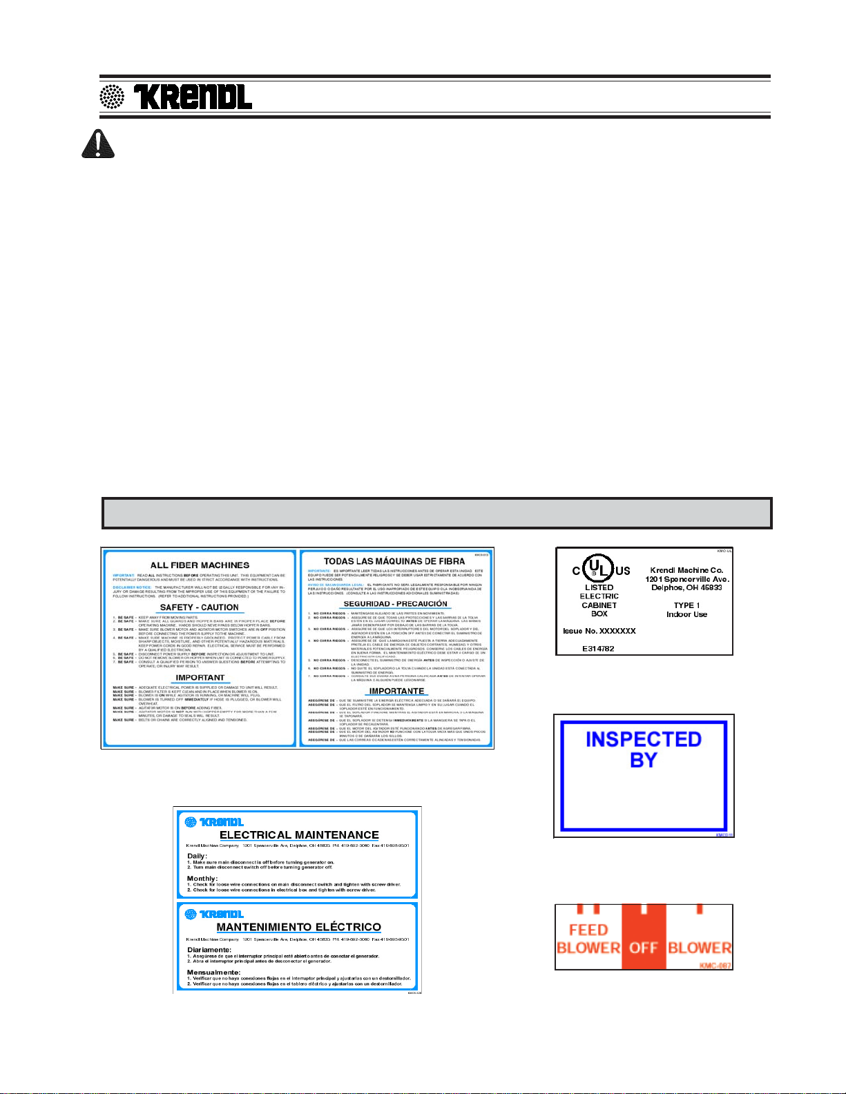
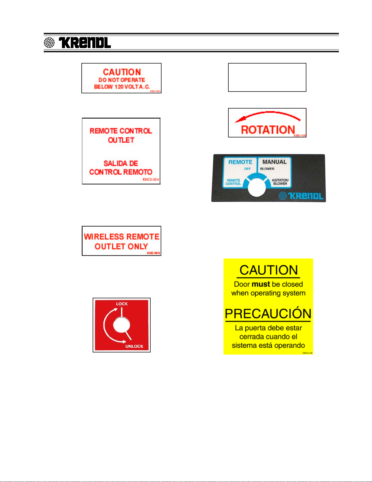
Always turn the main power switch (located on the electrical box) to off and unplug the remote cord
from the receptacle for any type of machine maintenance or adjustments. An additional safety feature
is the ability to adjust the material slide gate from the outside of the machine. Rotate the adjustment
handle clockwise to open the slide to the desired setting, no entrance into the machine is required.
All safety features are incorporated into the machine to protect everyone from serious
injury. Operate your machine according to the outlined instructions in the manual with all
guards in place and securely latched. Operation with any guards removed can result in injury
to or loss of fingers, hands, arms, toes, feet, legs, hair, and even your eyes.

Rev. Date: 12/14/10 Page4
MODEL #5200-P
Electrical Safety
• The National Electric Code (NEC) in the United States and many international electrical
codes require frame and external electrically conductive parts of this machine to be properly
connected to an approved earth ground. Local electrical codes may also require proper
grounding of machine. Consult with local electricians for grounding requirements in your area.
• Never handle any kind of electrical cord or device while standing in water, while barefoot or while
hands or feet are wet. Dangerous electrical shock will result.
• Useagroundfaultcircuitinterrupter(GFCI)inanydamporhighlyconductivearea. (metaldecking
or steel work)
• ReferenceNFPA79,70E,orOSHAsafeworkpracticeswhenpreformingenergizedworkprocedures.
Safety/Caution
•Be Safe - Keep away from moving parts.
• Be Safe - Makesureallguardsandhopperextensionsareinproperplacebeforeoperatingmachine.
Guards and safety devices/switches should not be removed, modified or by-passed.
Hands should never pass between rotating parts.
• Be Safe - Make sure remote control hand pendant switch is in off position before connecting the
power supply to the machine.
• Be Safe - Make sure machine is properly grounded. Protect all electrical supply cords from sharp
objects, moisture, and other potentially hazardous materials. Keep power cords in good
repair. Electrical service must be performed by a qualified electrician.
• Be Safe - Disconnect power supply before inspecting or adjusting unit.
• Be Safe - Consult a qualifiedtechnician to answer questions before attemptingtooperate, or injury
may result.
• Be Safe -Emergency Kill Switch - Incase of emergencies,always use redstopbutton locatedon
the front of Main Control Panel and on the side of the hopper. It will stop all feeding and
agitation.
•Be Safe - Do not remove motors or lift hopper when unit is connected to power supply.
• Be Safe - Do not operate machine alone.
• Be Safe - Do not leave machine unattended and energized.
• Be Safe - Turnmachine offand disconnect electricitybefore clearingandfeeding jamor attempting
to remove any object dropped in the hopper.
• Be Safe - Keephands,looseclothing,jewelryand hair away fromagitators,gears,chainsandother
moving parts.
• Be Safe - Use proper lifting when moving fibers and loading machine.
• Be Safe - Keep work area clear of debris.
• Be Safe - Wearpropersafetyequipment,includingprotectivegear,suchasrespirators,eyeandear
protection.
• Be Safe - Violation of the Owner's Manual or safety precautions may void warranty.

Rev. Date: 12/14/10 Page5
MODEL #5200-P
DECALS
Make Sure!
•Hopper is empty of foreign objects before starting.
• Adequate electrical power is supplied or damage to unit will result.
• Machine must be on before adding fiber.
• Blower filter is kept clean and in place when blower is on.
• Machine is turned off immediately if hose is plugged, or blower will overheat.
• Blower must be on, when agitators are running, or machine will bind.
• Agitatormotorisnotrunwithhopperemptyformorethanafewminutes,ordamagetosealswillresult.
• Sprockets, chains, belts and pulleys are correctly aligned and tensioned.
• Pieces of bag are not left in the machine as this can bind and stall your machine.
• This machine should only be used with good quality fibers that are dry, undamaged and that meet a
certain industry specification or quality standards.
IF THERE ARE ANY QUESTIONS WITH YOUR KRENDL MACHINE, DO NOT HESITATE TO
CONTACT US AT: 1-800-459-2069
General safety information intended to reduce the risk of serious
injury or death
Indicates which employee inspected equip-
ment and on what date.
Indicates that the electrical box on the ma-
chine is in compliance with UL codes.
Electrical maintenance information and schedule provided here.
Indicates if blower is off, on, or on with agitator.

Rev. Date: 12/14/10 Page6
MODEL #5200-P
Rotating parts can be dangerous! You can
snag clothes, skin, hair, hands, etc. This
can cause serious injury or death.
Manufacturer information is provided here
alongwithmachinemodel,andserialnumber.
Keeping the filter clean will result in longer
blower life and better performances.
Opens and closes the material feed gate
which in turn controls the production.
Identifies position of material feed gate.
Machine should be used with these products.
Made in the U.S.A.
Emergency stop button for machine.
Take caution when handling electrical cords
or electrical shock or death may result.
Read manual before operating machine for assured safety.

Rev. Date: 12/14/10 Page7
MODEL #5200-P
Rotatingpartswillbe movinginthisdirection.
KMC-01234
Part number for identification and tracking.
Operatingmachineatspecified voltagewill result
in longer machine life and better performance.
Identifies if machine is in remote mode, manual
mode,oroff position. Inmanualmode thisswitch
operates machine. In remote mode the hand
pendant operates machine. Each time machine
cycle starts, an audible alarm warns the opera-
tor that the machine is about to come on.
Indicates that this outlet is intended for only the
wireless remote. Each time machine cycle
starts, an audible alarm warns the operator that
the machine is about to come on.
Indicates that this outlet is intended for only the
remotecontrol outlet. Each timemachine cycle
starts, an audible alarm warns the operator that
the machine is about to come on.
Keepingthedoor closedwillkeep bystanders
safe from rotating parts.
Indicates if the latches on the access door are
lockedorunlocked

Rev. Date: 12/14/10 Page8
MODEL #5200-P
WARRANTY:
Krendl Machine Company (Company) warrants to each original purchaser (Buyer) of its
equipment or accessories that such products will be free of manufacturing defects for a period
of 12 months from the date of shipment to the Buyer.
No warranty is made with respect to:
1. Components or accessories manufactured and warranted by others. Warranties for
purchased component parts as supplied from vendor such as engine, electric motor,
blower, gearbox, transmission, etc., if furnished by the manufacturer of the component,
are on file at the Company’s main office and copies will be furnished at request of Buyer.
Component(s),shippingcostsprepaid,shallbesenttoCompanywhointurnshallforward
to vendor for evaluation and warranty determination.
2. Any defect caused by repair, alteration and/or adjustment performed by Buyer or
customer/vendor of Buyer without the express written authorization of the Company.
3. The labor costs of replacing parts by parties other than the Company.
4. Any machine that has not been operated and/or maintained in accordance with normal
industry practice and the written recommendations of the Company. (e.g. machine oper-
ated with an improperly sized, worn or damaged hose, improper or inattention to preven-
tative maintenance, etc.)
5. The product has been subjected to misuse, negligence or accident or results of any
application or use of the blowing equipment not in accordance with the Company recom-
mendations.
This limited warranty does not cover the free replacement of component parts that become
inoperative due to wear and usage and need to be replaced on a regular basis, including but
not limited to: airlock seal(s), agitator(s), shredder(s), auger(s), fuse(s), switch(es), clutch(es),
hose(s), shaft seal(s), chain(s), belt(s), sprocket(s), pulley(s), bearing(s), cable(s), battery(ies),
filter(s), fan(s), etc.
TheCompany’sobligationunderthiswarrantyislimitedtorepairingorreplacing(atCompany
option)anypartthatisdetermined bytheCompanytobesufferingfromamanufacturingdefect.
The Company (at Company option) will provide any required parts and labor to the Buyer. If the
equipment or parts must be returned to the Company for repair, all transportation costs shall
be the Buyer’s responsibility.
THIS LIMITED WARRANTY IS EXPRESSLY IN LIEU OF ANY OTHER GUARANTEES AND / OR
WARRANTIES, ORAL OR WRITTEN, EXPRESSED OR IMPLIED, INCLUDING WITHOUT LIMITA-
TION, THE IMPLIED WARRANTY OF MERCHANTABILITY. NO WARRANTY, EXPRESS OR
IMPLIED, OTHER THAN THE AFORESAID WARRANTY IS MADE OR AUTHORIZED BY COM-
PANY. COMPANY SHALL NOT BE LIABLE FOR ANY DIRECT, INDIRECT, INCIDENTAL OR
CONSEQUENTIAL DAMAGES TO PROPERTY OR INJURY TO ANY PERSON OR COSTS
ASSOCIATED WITH LOSS OF PRODUCTION RESULTING IN LOSS OF REVENUE, PROFITS
OR LOSS OF EQUIPMENT THROUGH THE USE OF THIS EQUIPMENT.
Note: Special job circumstances incurring costs for specialized repair and next day delivery
of parts will not be reimbursed by the manufacturer unless authorized by factory.

Rev. Date: 12/14/10 Page9
MODEL #5200-P
SPECIFICATIONS
MODELS: #5200-P
MACHINE: 14” Diameter x 18” Length airlock feeder
electromagnetic clutches on agitator and blower
in line helical gearbox (driving the machine)
HEIGHT: 83.00 inches
LOAD HEIGHT: 59.00 inches
WIDTH (DEPTH): 43.00 inches
LENGTH: 80.00 inches
WEIGHT: 2000 pounds
ELECTRICAL: 12VDC remote control system (6000 watt generator supplying
120VAC to convenience outlets & accessories)
BLOWER VOLUME: 250CFM
BLOWER PRESSURE: 6.0 PSI maximum
HOSE OUTPUT: 4” diameter
MAXIMUM FEED RATES:
CELLULOSE: 5200 lbs./hr. FIBERGLASS: 2300 lbs./hr.
WARNING:Recommended hose size, type and length must be used to achieve maximum
results. Krendl cannot guarantee performance of the #5200-P machine if hoses are
undersized, worn, damaged, or hoses other than those we recommend are used.
BEFORE YOU RUN THIS MACHINE...PLEASE READ THE REST OF THIS MANUAL!!
RETURNED GOODS PROCEDURE
IF MACHINE WAS NOT PURCHASED DIRECTLY FROM KRENDL MACHINE COMPANY, CON-
TACT YOUR SUPPLIER / DISTRIBUTOR.
When returning products to Krendl for repair, first obtain a return goods authorization (RGA), at
which time you will be given shipping instructions. The product must be shipped PREPAID:
Krendl Machine Company Telephone: 419-692-3060
1201Spencerville Ave. Fax: 419-695-9301
Web Site: www.krendlmachine.com
Once the unit is received, it will be inspected. In-warranty units will be repaired and returned
immediately. An estimate of repair charges will be provided for out-of-warranty units.

Rev. Date: 12/14/10 Page10
MODEL #5200-P
BASIC COMPONENTS
This is a view of the basic components of your Model #5200-P machine. It shows the location of
each item and gives the function of each. Use this as a guide throughout the manual.
(Illustration 1)
A) BaseUnit-Lowerframeunitsupportingblower
box, speed reducer, motor, airlock and hopper.
B) Airlock - Traps air and fiber while providing a
metered flow.
C) Shredder System - Increases production and
coverage on all fiber products while reducing
clumps that may exist in various fibers.
D) Slidegate-Meterstheamountoffiberdropping
into the airlock by controlling size of airlock
opening.
E) Speed Reducer - Increases outputpower while
decreasingspeedofagitator/airlockdrivemotor.
F) Agitator - Conditions fiber in the hopper.
G) Hopper - Upper unit of machine holding fiber.
(Illustration 2)
H) Main Control Panel - Connects with main
power, allowing operation of unit at machine or
Remote Cord.
I) Kill Switch - Safety device for immediate stop-
ping of machine.
J) Blower - Provides the air necessary to move
fiber from the airlock.
K) Hydraulic Motor - Provides driving power for
speedreducer, blower,generator,and agitator/
airlock system.
L) Generator - Provides power to all auxiliary
electrical components.
M) Hopper Extension -Increases overall hopper
capacity.
Illustration 1
Illustration 2

Rev. Date: 12/14/10 Page11
MODEL #5200-P
INSTALLATION
MACHINE DRIVE AND TRUCK SPECIFICATIONS:
Your Model #5200-P Krendl Machine can be mounted in any truck and chassis configuration. We
recommend a minimum chassis rating of 26,000 GVWR. We also recommend a minimum 22 feet van
body.The body shouldhave afullwidthrear door.The Krendl Model#5200-PMachine can bemounted
anywhere in the truck body. The factory recommended positions are shown in Illustration 3.
TOOLS NEEDED: CUSTOMER SUPPLIED ITEMS:
1/2” Heavy Duty Drill 1/2” Bolts,washers, locknutsforfastening machine
Drill Bits: 9/16” for bolts
Fork Lift (means to lift the machine)
Pry Bars
Basic Wrenches
5” hole saw & 2” hole saw
INSTALLATION INSTRUCTIONS:
1) Place the machine in either of the two locations so that the machine will not be in the way of the
truck’s doors and you are still able to open the hood of the machine.
2) Using illustration 3 as a reference, check under the truck body that the opening will not interfere
with any truck components underneath. If there is any interference with any of the truck parts,
thenyou willneedto adjusttheposition ofthe machine toclear the obstruction. Theholes for the
blower inlet and machine hold down do not have much room for adjustment. However, the holes
for the hydraulic lines do have room for slight adjustments.
Illustration 3
3) Remove the machine after the holes are located.

Rev. Date: 12/14/10 Page12
MODEL #5200-P
A
B
A
B
4) Cut the following holes: (Using illustration 4 as reference ONLY)
a. Blower Inlet: 5”
b. Hydraulic Lines: 2”I
Illustration 4
5) Place the machine in the truck lining it up with the holes.
6) Locate and drill 9/16” holes for the four hold down holes located in the bottom of the base flange.
Again, check the underside of the truck body for any obstructions. Use 1/2” bolts and nuts to bolt
the base to the truck floor.
7) Run hydraulic lines to the machine.
8) Attach hydraulic lines to the hydraulic motor. Note: The shaft on the hydraulic motor should be
running counter clockwise. If the motor is running in the wrong direction, disconnect the hydrau-
lic lines and reverse the hook-up.
HydraulicLines

Rev. Date: 12/14/10 Page13
MODEL #5200-P
10) Coming off of the positive terminal on the truck battery, attach a 15 amp inline circuit breaker.
11) Run power from the truck battery to the machines electrical box.
12) Attach 4” hose to the filter box inlet so that the hose sticks through the 5” hole cut into the floor of
the truck.
If you need more information, please call your sales agent. Your Krendl Model #5200-P Machine is
now ready for operation.
Your Krendl Model #5200-P Machine was checked and thoroughly run before it was shipped but it
is always a good idea to check all belts and chains for proper tension and that all fluid levels are
checked and topped off where required.
15Amp Circuit Breaker
Red wire from battery to
power distribution block
White wire from battery to
block three (3)

Rev. Date: 12/14/10 Page14
MODEL #5200-P
OPERATING INSTRUCTIONS
StartingYourKrendl Model5200-PMachine:
1) After installing your Model #5200-P according to the installation instructions, it is now time to start
your machine. Again, check all fluid levels, belt tension, and that all guards are installed properly.
2) Attach the blowing hose to the machine and run the hose into the building.
3) Run the remote control cord into the building.
4) Make surethe ControlSwitch onthe remote controlcord isin theOFF position. Now, youmay plug
in the remote control cord.
5) With truck engine running engage PTO. Make sure PTO is running at proper speed. (With Main
Disconnect ON generator voltmeter should read 120 volts.)
6) Your machine is now ready for operation.
Note: Agitator motor and blower should only be operated with steady or constant flow of electricity
between 110-120 volts.
Note: When using extension cords, wire gauge size should not be less than input cord on unit and
not exceed 50' in length. (See Voltage Drop Chart Below.)
Ex: A two-wire 20-ampere circuit using 12 AWG with a one-way distance of 25 feet will drop 1.98 volts;
120 volts - 1.98 volts = 118.02 volts as the load voltage.

Rev. Date: 12/14/10 Page15
MODEL #5200-P
ElectricalOperation:
NOTE: PRESS KILL SWITCH TO IMMEDIATELY STOP MACHINE AT ANY TIME!
1. Make sure Kill Switch is out by twisting clockwise/right. (See illustration 5)
2. Turn red Main Disconnect Switch to ON position. (See illustration 5)
3. Set 4-Position Selector Switch to OFF. (See illustration 5)
4. Press green start Button. Machine will not run unless start button is pressed after Kill Switch
is out and red Main Disconnect Switch is on. (See illustration 5)
5. Select operating mode on 4-Position Selector Switch from one of the following options:
Remote: Remote control hand pendant will control machine.
Off: Machine will not run. (overrides remote hand pendant)
Blower: Only the blower will run continuously. (manual control at machine)
Agitator-Feed/Blower: Both the blower and the agitator-feed will run continuously. (manual
control at machine)
Main Control Panel (lid closed)
Illustration5
Main Control Panel (back)
Illustration6

Rev. Date: 12/14/10 Page16
MODEL #5200-P
6. When operating in Remote mode, the 4-Position Selector Switch must be set to Remote
position. (See illustration 5 on page 15.)
7. Remote control hand pendant positions will be selected from the following:
BLOWER-FEED -operatesboth blower andagitator-feed simultaneously
OFF - (middle position) all functions stop
BLOWER - operates the blower only
8. UsetheAuxiliary Outletonthe MainControlPanel for supplyingcontinuous power (while redMain
Disconnect Switch is ON) to accessories.
StoppingYourMachine:
1) Switch the Remote Switch to “AIR ONLY” and wait until the hose is clear of all material.
2) Turn the Control Switch on the remote control cord to the OFF position.
3) Turn the Main Disconnect Switch to the OFF position.
4) Disengage the PTO.
SAFETY NOTE:
DO NOT FILL THE HOPPER TO CAPACITY AT THE END OF THE DAY. THE MATERIAL
WILLCOMPRESSAND CAN CAUSE MACHINE LOCKUP DURINGTHE NEXT START-UP.
MechanicalSettings:
The controls of your machine contain the blower and slidegate controls to adjust your machine for
each application and type of fiber. (See illustration 7 on page 17.) Blower control (air) and slidegate
(material feed) are adjusted according to:
TYPEOFMATERIAL: Cellulose and fiberglass have different textures and densities that
respond to machine settings.
HOSE: Corrugations or roughness of interior surface, diameter, length and
elevation of hose will also require varying adjustments.
WEATHER CONDITIONS: Temperature and humidity may require day to day adjustment of
machine settings.
Blower Control and Slidegate General Settings:
Blower control can increase or decrease the amount of air in the system, affecting the velocity
(speed) and spread rate (coverage) of fiber. (See illustration 7 on page 17.) The blower control valve
is used for controlling air pressure and amount of air flow.
Opening or closing slidegate (material feed) controls the amount of fiber dropping into the airlock
which changes the production rate (lbs. per hour). (See illustration 7 on page 17.) For calibration
purposesthe scalelocated onthe machineindicates how manyinches theairlock slidegateis opened.

Rev. Date: 12/14/10 Page17
MODEL #5200-P
The blower and slidegate controls working together
affectthe distancefiber canbeblown througha hosewithout
plugging. These controls also affect the accurate blowing of
fibers for spraying applications.
These settings control the following:
•Density of fiber blown in application.
•Velocity of material impact when spraying.
•Dust on open blow.
• Material spread rate or coverage.
•Production rate (lbs. per hour blown).
General Blower Control and Slidegate Settings for Open Blow:
With the slidegate closed and blower control valve on low (valve open), turn agitator-feed and
blower on. Fill hopper with insulation and adjust blower valve and slidegate. Move controls
proportional to each other. (i.e. If blower valve is half open, slidegate should be half open.) As hose
length is increased, air pressure/volume is increased by closing off the blower valve while closing the
slidegate proportionally. This will increase the distance fiber can be blown through the hose, while
decreasing the blowing production rate (lbs. per hour blown). (See illustration 7)
Shredder Assembly:
This unit is supplied with a shredder assembly; airlock/agitator speeds are preset at the factory. No
further sprocket setting speeds are needed, as this system will accommodate most fibers and
applications. However, the shredder and agitator direction can be adjusted as described below.
Shredder & Agitator Adjustment:
Illustration 7
Unidirectional Rotation (See illustration 8) is preferred as an all-around setting for a combination of
materials and applications. This setting provides the greatest coverage and best control for internal
wetting (stabilized) and open blow applications.
Center-Down Rotation (See illustration 9) force feeds the fiber into the airlock at a faster rate. This
direction provides the greatest production for cellulose fibers in an open attic blow application
although coverage may decrease.
Illustration 8 Illustration 9
Table of contents
Other Krendl Industrial Equipment manuals
Popular Industrial Equipment manuals by other brands

Power-Tronics
Power-Tronics SE3000B-3P manual

Alfalaval
Alfalaval ALT-SB-15 instruction manual

Edgetech
Edgetech 3300 Installation guidelines

Blue Diamond
Blue Diamond Post Driver Operator's manual

Linon Home Decor Products
Linon Home Decor Products Powell 16A8213C quick start guide

New lift
New lift EAZ-TFT manual

System air
System air SAVE VTR 250/B user manual

Delta
Delta WHITEWATER DF Series Installation, operation and maintenance manual

Power-Tronics
Power-Tronics PT-3000 user manual

Soler & Palau
Soler & Palau Flexeo BP 210 FL 3V manual

Alfalaval
Alfalaval T2 instruction manual

Premier Manufacturing Co.
Premier Manufacturing Co. 160HD Installation, Inspection, Operation & Maintenance Guide