AGRI-COVER ACI SRT-2 User manual

Thank you for purchasing SRT-2TM Electric Tarp Conversion. Agri-Cover, Inc. proudly
manufactured this tarp using superior quality materials and workmanship. With proper
care, your tarp will provide years of service.
NOTICE TO INSTALLER: Even if familiar with product, read instructions prior to
installation as improvements may be made without notice. Always handle components
with care. If you have questions or problems, have serial number ready and call
customer service. When done, these instructions must be given to the consumer.
NOTICE TO CONSUMER: Before using this product read operating, maintenance and
safety sections. Save these instructions for future reference.
INSTALLATION INSTRUCTIONS
Questions? (800) 233-4655
agricover.com
FOR YOUR RECORDS
DATE PURCHASED:
WHERE PURCHASED:
TARP SERIAL NUMBER:
(Located on motor and gearbox)

2
PREPARATION
• Prior to tarp system assembly, park truck or trailer on level ground.
• Box must be square and straight, center must not be pulled together or spread apart.
• Remove or grind smooth any sharp edges or points contacting tarp and/or cables.
• Remove or reposition any interferences with motor. If modications to box are
needed, consult box manufacturer.
• Ensure box extension is secure by bolting in place on top of your box.
TOOLS NEEDED
• (2) 1/2” Wrenches
• Step ladders or scaffolding
• Drill with 5/16” and 3/8” bits
• Protective eyewear
• Cutting tool(s)
• Marking pencil
• 9/16” Wrench
• Tape measure
NOTE: Hardware appearance and components may vary.
!CAUTION: Before drilling, ensure there are no hidden wires or gussets in line
with holes to be drilled.

2 3
SAFETY INFORMATION
!DANGER: Mounting replacement tarp to a structurally weak or damaged roll
tube can result in serious injury or death.
Before installing replacement tarp, inspect mounting surface of roll tube. Be aware
several mounting holes in close proximity may compromise roll tube strength and
integrity. Ensure mounting location on roll tube provides adequate tarp support.
• Disconnect power before servicing tarp system or electrical components.
• Always use caution when operating tarp system.
• Ensure people and objects are clear of tarp system before and during operation.
• Instruct everyone who will operate tarp system on the proper procedures.
• Never allow children to operate or play with tarp system.
• Do not operate tarp system with box hoisted in elevated position.
• Ensure tarp system is fully open or fully closed before operating vehicle at highway
speeds.
• Only operate tarp system when tarp is completely visible.
• Always refer to OEM instructions before installing electrical components.
• Do not use arm as a step.
• Remove snow or debris from top of tarp system before operating.
• End caps must be free from commodity. Commodity should not be piled higher than
end caps.
• Do not directly spray motor or connections with a pressure washer.
• Ensure tarp system is fully open before unloading or loading.
NOTE: Safety and operating procedure decals provided with this kit should be kept
clean at all times and replaced if worn, damaged, painted over or unreadable.

4
1: ATTACHING MOTOR
A. Place and weld motor mount slide frame to center of belly dump’s cross frame.
B. Mount motor to motor mount carriage with (3) 5/16” x 3/4” hex bolts and washers.
C. Slide motor on motor mount slide frame with motor facing front of trailer.
D. Attach face plate to motor mount slide frame using (2) 5/16” x 2” bolts, washers and
nylon nuts.
E. Attach drive shaft with U-joint to motor drive shaft.
F. Ensure motor is 1-1/2” from back of motor mount slide frame.
Motor
5/16” Nylon nut
5/16” x 2” Bolt
and washer
Face plate
Motor mount
slide frame
Drive shaft
with U-joint
Motor
Motor mount
carriage
5/16” x 3/4”
Hex bolt and
washer

4 5
2: INSTALLING U-JOINT
A. Temporarily attach U-joint with extension to drive shaft using cotter and clevis pins.
Do not bend cotter pin tabs.
B. Remove clevis and cotter pins holding PVC spacer on cartridge protruding from
spool. Slide U-joint with extension into PVC spacer and cartridge.
C. Test for clearance then secure U-joint with extension to drive shaft with clevis and
cotter pins.
NOTE: If necessary, cut drive shaft to length then drill 5/16” hole using hole in U-joint
with extension as guide.
D. Use hole in end of PVC spacer and cartridge as guide to drill a 5/16” hole in U-joint
extension, then secure with clevis and cotter pins. Bend all cotter pin tabs.
TIP: Periodically grease motor drive shaft and extension.
Long PVC spacer
and cartridge
Clevis and
cotter pins
U-joint with
extension
Drive shaft

6
3: ELECTRICAL
A. Locate and clean suitable locations to apply caution stickers.
B. Refer to included instructions to complete wiring.

6 77
INSPECTION AND MAINTENANCE
Periodic preventive maintenance should be practiced:
• Inspect tarp and hardware for abrasions or loosened bolts that may need adjustment.
Adjust tension when needed. Tarp must be kept to a recommended tension setting
equally on both ends, or excessive tarp wear may occur.
• Tarp should always operate as well as when rst installed. Make all appropriate
repairs or adjustments immediately before serious damage occurs.
• Check the tightness of mounting bolts and electrical connections, remove any dirt or
corrosion that may have accumulated on the electrical connections.
• Always use genuine Agri-Cover, Inc. replacement parts, use serial number to easily
order replacement tarp.
For Replacement: 1-800-233-4655
EZL/ATL Part #: KA-116132A010
SERIAL: 123456789 18.12.2015
Serial number is located at rear
of tarp on stationary tube side

102820 200337_
Agri-Cover, Inc. extends the following Limited Warranty on its SRT-2TM Electric Tarp
Conversion:
Agri-Cover, Inc. warrants its SRT-2TM Electric Tarp Conversion to be free from defects in
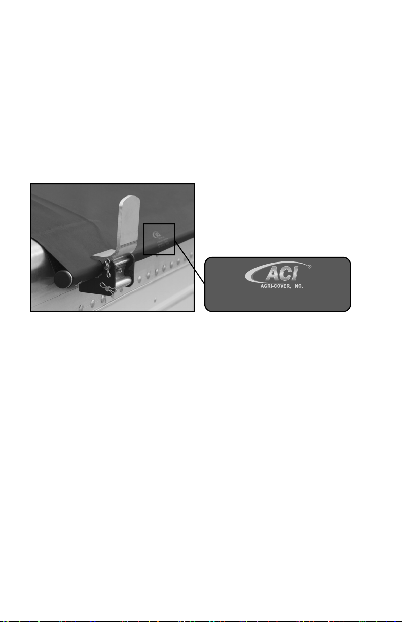
material and workmanship under normal use for one (1) year from date of manufacture
unless accompanied by proof of purchase. The one (1) year warranty start date can be
found on the unit (motor and gearbox). Check both and refer to the oldest date shown.
This Limited Warranty does not cover any failure due to abuse, misuse, alteration, neglect,
improper assembly or installation, or improper maintenance.
ANY IMPLIED WARRANTY APPLICABLE TO THE SRT-2TM ELECTRIC TARP
CONVERSION IS LIMITED IN DURATION TO ONE YEAR FROM THE DATE OF
MANUFACTURE UNLESS ACCOMPANIED BY PROOF OF PURCHASE. Agri-Cover
Inc.’s sole obligation under this Limited Warranty or any implied warranty is limited to the
repair or replacement at its option, of defective parts only. No labor or service allowance is
given or implied. IN NO EVENT SHALL AGRI-COVER, INC. BE LIABLE FOR INCIDENTAL,
CONSEQUENTIAL, OR SPECIAL DAMAGES. EXPRESSLY DISCLAIMS ANY AND ALL
IMPLIED WARRANTIES OF MERCHANTABILITY, AND THERE ARE NO WARRANTIES
WHICH EXTEND BEYOND THE LIMITED WARRANTY DESCRIPTION CONTAINED
HEREIN.
For warranty, have serial number ready and ll out the warranty claim form at
agricover.com/warrantyclaim or call Customer Service Department at 800-233-4655 to
determine if only a replacement part is needed or if the tarp needs to be returned for
inspection and repair. Goods to be returned must have a pre-authorized RA # (Return
Authorization Number) – obtained by calling the number above. Mark the number on the
package and ship it freight prepaid to address below. Agri-Cover will pay freight to return
goods to sender.
This Limited Warranty gives you specic legal rights and you may have other rights, which
vary, from state to state.
For replacement parts shop at agricoverparts.com or call Customer Service at
800-233-4655.
MANUFACTURER’S LIMITED WARRANTY
Hours: 8:00 am - 5:00 pm CST Monday through Friday, except Holidays
Agri-Cover, Inc.
Customer Service Dept
3000 Hwy 281 SE
Jamestown, ND 58401
Phone: 800-233-4655
© 2020 AGRI-COVER, INC. ALL RIGHTS RESERVED.
Product subject to change without notice. Patents: agricover.com/patents.
Table of contents
Other AGRI-COVER Tractor Accessories manuals