Agri-Fab 45-03088 User manual

45-03088
FORM NO. 28178 (04/22/19)
IMPORTANT! The engine is shipped without oil. Oil must be added
before starting the engine. See Engine Maintenance on page 10 of
this manual for instructions.
IMPORTANT! Check engine air lter prior to each use. Follow the
maintenance schedule on page 8 of this manual.
the fastest way to purchase parts
www.speedepart.com
youtube.com/c/agrifab
Video
Instruction
Guide
Want more information or assembly tips?

2
SAFETY RULES .............................................................3
ASSEMBLY .....................................................................4
OPERATION.................................................................5-7
MAINTENANCE.........................................................8-10
SERVICE AND ADJUSTMENT .................................11-12
TABLE OF CONTENTS
Congratulations on your purchase of a tow behind tiller. It
has been designed, engineered and manufactured to give
you the best possible dependability and performance.
Please read and retain this manual. The instructions will
enable you to assemble and maintain your tiller properly.
Always observe the SAFETY RULES.
MODEL NUMBER: 45-03088
SERIAL NUMBER: ____________________________
DATE OF PURCHASE:_________________________
THE MODEL AND SERIAL NUMBER WILL BE FOUND
ON THE MODEL PLATE ATTACHED TO THE RIGHT
HAND CHASSIS.
YOU SHOULD RECORD BOTH SERIAL NUMBER
AND DATE OF PURCHASE AND KEEP IN A SAFE
PLACE FOR FUTURE REFERENCE.
CUSTOMER RESPONSIBILITIES
• Read and observe all product safety rules.
• Follow the instructions under MAINTENANCE and
STORAGE sections of this Owners Manual.
PRODUCT SPECIFICATIONS
OIL (20 oz. Capacity): Above 32 F: SAE 30
Below 32 F: SAE 5W30
TILLING GROUND SPEED: Approx. 2 MPH
TILLING WIDTH: 36 in.
TILLING TINE SPEED: 230 RPM
STORAGE ..................................................................... 12
TROUBLESHOOTING .................................................. 13
REPAIR PARTS........................................................ 15-17
PARTS ORDERING/SERVICE........................Rear Cover

3
SAFETY
TRAINING
• Readassembly,operation,andserviceinstructionscarefully.
• Be thoroughly familiar with the controls and the proper use of the equipment.
• Towing vehicle's braking and handling may be affected with the use of a tiller or other attachment. Know how your
towing vehicle handles with the use of an attachment. Refer to towing vehicle owner's manual.
• Neverallowchildrentooperatethemachine.Donotallowadultstooperatethemachinewithoutproperinstruction.
PREPARATION
• Do not ll the gasoline tank while the engine is running or still hot.
• Do not ll the gasoline tank indoors.
• Wipe off any spilled gasoline before starting the engine.
• Inspect the area to be tilled. Dial 811 to have underground pipes and wiring located prior to tilling. Remove glass,
wire, metal objects, large sticks, and stones.
OPERATION
• Keep the area of operation clear of all bystanders, particularly small children and pets.
• Personalinjurymayresultfromdebristhrownbythismachine.
• Neverplacehands,feet,orlooseclothingunderorintorotatingpartsorconcealedareas.Keephandsandfeet
clearly away from auger elements, belts, pulleys, etc. while engine is running.
• Neveroperatemachinewithoutproperguards,plates,orothersafetyprotectivedevicesinplace.
• Neverstoretillerinsideabuildingwhilegasolineisinthetank.Allowenginetocoolbeforestoringinanenclosure.
• Stopengineanddisconnectsparkplugleadwirebeforecleaningaugers,removingobstacles,ormaking
adjustments. Refer to engine manual.
• Neverruntheengineindoors.
• Disengagethetineclutchleverandstopthetillerandtractorenginesbeforegettingoffthetractor.
• Wearclosedtoeshoesandeyeprotectionwhileusingtiller.
• Slowly engage clutch lever when tilling harder soil. Refer to operation section.
• Operatethetillerindaylightorgoodarticiallight.
• Alwaysproceedslowlyandcarefullywhileoperatingtiller.
This unit is equipped with an internal combustion engine and should not be used on or near any unimproved forest
covered, brush covered, or grass covered land unless the engine's exhaust system is equipped with a spark arrester
meeting applicable local or state laws (if any). If a spark arrester is used, it should be maintained in effective working
order by the operator. In the state of California the above is required by law (Section 4442 of the California Public
Resources Code). Other states may have similar laws. Federal laws apply on federal lands. A spark arrester muffler is
available at your nearest authorized engine service center.
Look for these symbols to point out important safety
precautions. It means — ATTENTION! Become alert! Your
safety is involved.
Failure to follow safety instructions could result in death or serious injury.

4
3/8" NYLOCK
NUT
FIGURE 1
FIGURE 2
FIGURE 3
FIGURE 4
REMOVE UNIT FROM CARTON
• Cut all four corners of the carton from top to bottom
and lay panels at. See gure 1.
• Remove the lag screw that holds the oating hitch to
the packing skid.
• Remove wooden top and side supports.
• Remove four hex bolts, hex nuts, and at washers
from the hold down brackets at the rear of the carton.
• Remove and save the two at washers and cotter
pins from the rear axle. Reuse when attaching gauge
wheels.
• Discard all other packing hardware.
INSTALL TILLER GAUGE WHEELS
• Assemble gauge wheels onto rear axle with the
extended end of the hub facing inward. Secure with
the at washers and cotter pins that were removed
from the axle during unpacking. See gure 2.
INSTALL TILLER TINE ASSEMBLIES
• Attach oating hitch to tractor draw bar (Refer to
OPERATING INSTRUCTIONS on page 6.)
• Remove the pre-assembled 3/8" x 2" hex bolt and
3/8" nylock nut from the left hand tine assembly. Slide
the tine assembly onto the transmission axle on the
left side of the tiller and secure with the hex bolt and
nylock nut. See gure 3. Repeat for opposite side.
INSTALL (WHEEL) WEIGHTS TO TILLER
NOTE: Weights are not furnished with the tiller. Wheel
weights may be purchased to mount to the tiller if extra
weight is required. (Refer to the OPERATION section of
this manual.)
• Remove the four hex bolts and nuts located
approximately 3-1/2" from the front edge of the tine
shields. See Figure 4.
• Secure (wheel) weights to tine shield using bolts and
nuts furnished with the weights. See Figure 4.
ASSEMBLY

5
RIGHT HAND (RH) AND LEFT HAND (LH) ARE
DETERMINED FROM THE DRIVERS POSITION
WHILE SEATED ON THE TRACTOR.
KNOW YOUR TILLER
Compare the illustration below with your tiller to familiarize yourself with the location of various controls and adjustments.
WE RECOMMEND THAT YOU REMOVE THE MOWER
DECK BEFORE USING THE TILLER. REFER TO
YOUR TRACTOR OWNER'S MANUAL.
FIGURE 5
SAFETY SWITCH - prevents engine from starting while
tine clutch lever is engaged
LIFT HANDLE - selects tilling or transport position by
moving gage wheels
TINE CLUTCH LEVER - starts and stops tine rotation
FLOATING HITCH - telescoping hitch limits shock loads
to tractor
RECOIL START HANDLE - used to start the engine
THROTTLE CONTROL - controls engine speed
FUEL SHUT OFF - shuts of fuel to engine
CHOKE CONTROL - used when starting a cold engine
DEPTH STAKE - controls tilling/cultivating depth
TINE
CLUTCH
LEVER
THROTTLE
PULL START
FUEL
SHUT
OFF
CHOKE
CONTROL
LIFT HANDLE
FLOATING HITCH
DEPTH STAKE
OPERATION

6
Never ll fuel tank indoors, or with the engine running, or
while the engine is hot. Do not smoke while lling tank.
Moving belt can crush and cut. Do not operate with belt
guard removed. Always disengage clutch lever before
starting
The muffler and adjacent areas are hot!
• Check oil and gas in tiller engine.
• Attach spark plug wire to spark plug.
• Pull forward on tine clutch lever to disengage tines.
A safety switch prevents engine from starting while
tines are engaged.
• Turn shut off to "ON" position.
• Move choke lever on engine to CHOKE position. (A
warm engine may not require choking.)
• Move throttle control lever on engine to FAST position.
• Grasp starter handle and pull rope out slowly until
engine reaches start of compression cycle (rope will
pull slightly harder at this point). Let the rope rewind
slowly.
• Keep a rm grip on starter handle and pull rope with
a rapid, continuous, full arm stroke. Let rope rewind
slowly. Do not let starter handle snap back against
starter.
• Repeat instructions in two preceding paragraphs until
engine starts. After engine starts, move choke control
gradually to RUN position.
• Allow engine to warm up for a few minutes before
engaging tines.
HAIR COTTER PIN
1/2" NYLOCK
NUT
HEX BOLT,
1/2-13 X 1-1/4"
HITCH PIN
FLOATING
HITCH
HITCH BRACKET
EXTENSION
TRACTOR
DRAWBAR
STOPPING YOUR TILLER
TINES
• Pull forward on the tine clutch lever to disengage
tines.
• Raise tiller to transport position.
ENGINE (Refer to separate engine manual.)
• Move throttle control to "STOP" position.
• Turn shut off to "OFF" position.
• Never use choke to stop engine.
STARTING YOUR TILLER
• BEFORE STARTING YOUR TILLER FILL THE
ENGINE WITH OIL! Your tiller engine is shipped
without oil or gasoline. Add oil as instructed in
ENGINE MAINTENANCE on page 9 of this manual.
Add gas as instructed in the engine manual.
FIGURE 6
Flying debris can cause eye injury. Always wear eye
protection before starting and while operating tiller.
HOW TO USE YOUR TILLER ATTACHING TILLER TO TRACTOR
(See Figure 6)
• Rear wheel weights and tire chains can be used on
tractor if additional traction is required for tilling.
• Place tiller on level ground and back tractor up to it.
• Attach hitch bracket extension to oating hitch of tiller
using a hitch pin and hair cotter pin.
• Fasten hitch bracket extension to tractor drawbar with
a 1/2-13 x 1-1/4" hex bolt and 1/2" nylock nut.
• Hitch bracket extension can be attached as shown in
gure 6 or turned upside down for tractors with lower
drawbars.
BREAKING IN YOUR TILLER
Break-in your belts, pulleys, and the control before you
actually begin tilling.
• Start engine with tiller attached to tractor in transport
position. Engage tine clutch lever to start tine rotation.
Allow tines to rotate for ve minutes.
• Check tine operation and adjust if necessary. See
TINE OPERATION CHECK in the SERVICE AND
ADJUSTMENTS section of this manual.

7
TRANSPORTING YOUR TILLER
• Pull forward on lift handle until it locks in the transport
(up) position.
• Disconnect spark plug wire.
• Drain fuel tank.
• Transport in upright position to prevent oil leakage.
• Do not transport on roads or public thoroughfares
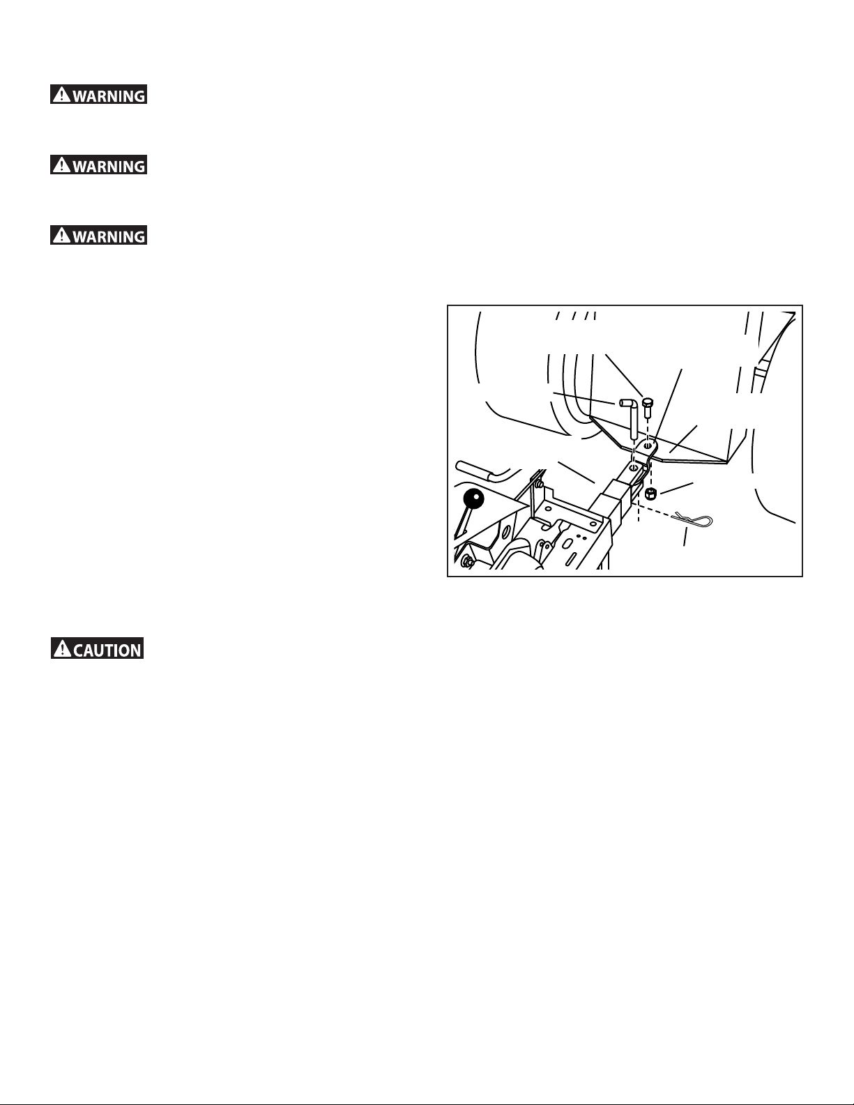
TO ADJUST DEPTH STAKE
• The top depth stake hole selects a till depth of 1"
with each lower hole increasing till depth by 1" to a
maximum of 5".
• To change till depth, remove the hair cotter pin from
the clevis pin which is connecting the depth stake to
the stake support bracket.
• Grasp the top of the depth stake, remove the clevis
pin and reposition the depth stake. Insert clevis pin
and hair cotter pin.
Removing the depth stake could result in loss of control of
the towing vehicle and result in injury.
TILLING
• Tilling should be done with the tiller engine full
throttle. If tiller engine seems to be overloaded or
stalls out, lower gauge wheels for shallower tilling.
• Operate tiller engine at full throttle and operate tractor
in slowest forward speed with tractor engine at idle
speed or just above idle.
• Soil conditions will determine how deep tiller can
penetrate on the rst pass. In extremely hard ground,
several passes may be necessary to till to a depth of
6 inches. While in soft ground, tiller may penetrate to
a depth of 6 inches in the rst pass.
TILLING HINTS
IMPORTANT OPERATING HINTS
NOTE: The following are general guidelines for tilling, but
may vary depending upon soil conditions.
• In virgin soil, the tiller should be started in shallowest
depth position and lowered one position at a time
after each pass in each direction.
• Extremely hard and dry soil will need to be cross tilled
at a shallow depth rst, then tilled in the direction of
planting rows on the second pass at the nal depth.
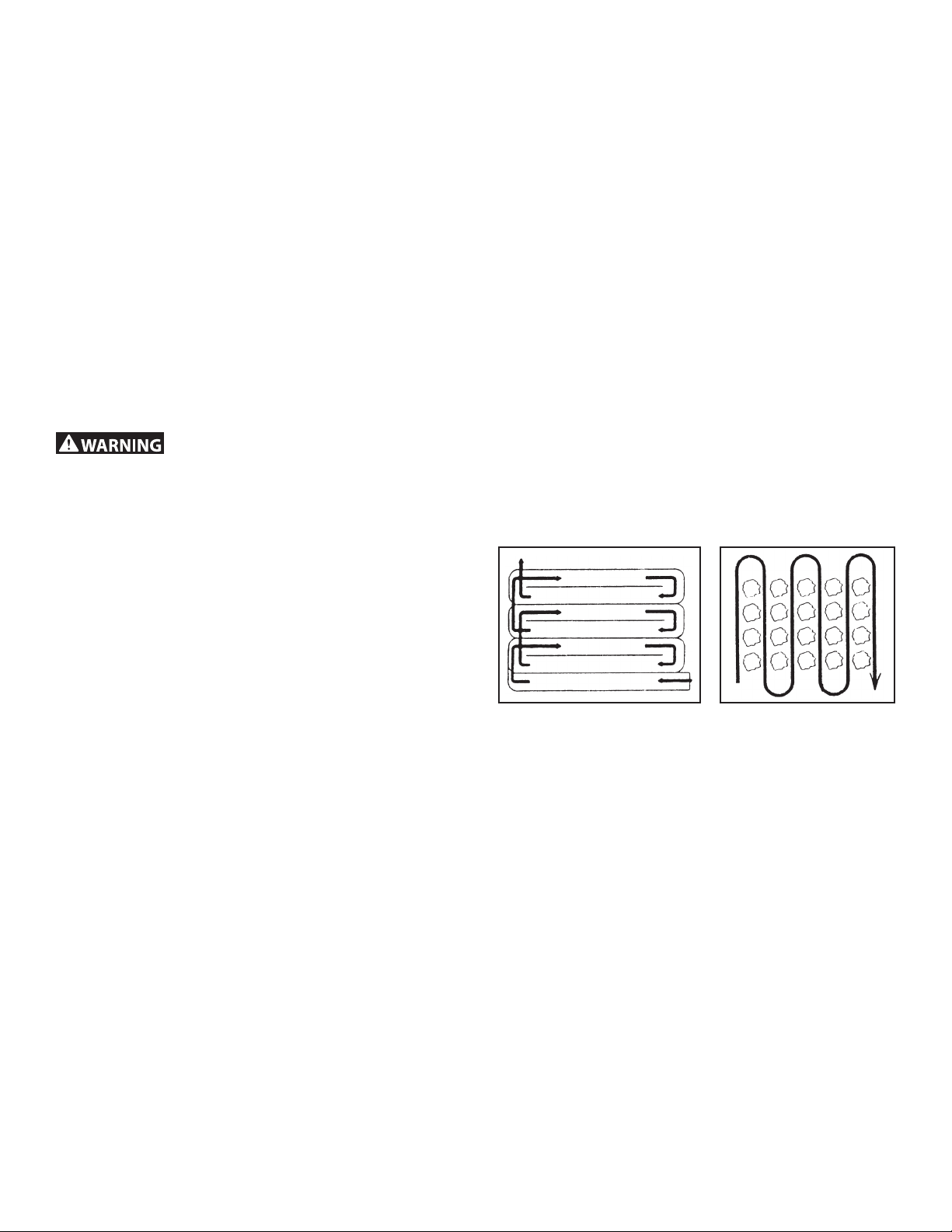
• Till in a pattern similar to that shown in Figure 7. Make
the rst pass, skip a space equal to the width of the
tiller and make the return pass, then till the skipped
area. Tilling in this pattern will enable you to maintain
better control. If the passes are made side-by-side,
the tractor and tiller will pull toward the tilled (soft)
side.
• Check ground moisture. The ground is too wet if you
can make it into a ball with your hand. Tilling soil
when it is too wet will cause lumps which are difficult
to work up.
• In soil that was tilled the year before, select the tilling
depth at which the tiller engine runs comfortable and
does not stall or pull down. Lower depth for additional
passes if great depth is desired.
• Whenever working multiple passes, go perpendicular
to the previous tilling direction.
• In cases where the soil is too hard to get proper
penetration or if tiling action causes tiller to hop or
bounce, it will be necessary to purchase a set of tiller
(wheel) weights.
CULTIVATING
• A minimum of two (2) inches of soil penetration is
required for cultivating.
• Set depth stake so the tiller penetrates soil to a depth
of 2 to 3 inches.
• Run the tiller engine at full throttle except when
cultivating small plants. A slower engine speed
is necessary to prevent burying small plants.
See Figure 8.
FIGURE 7 FIGURE 8

8
Service Dates
MAINTENANCE SCHEDULE
Fill in dates as you
complete regular service.
Before each use
First 5 to 8 hrs.
25 hrs. or
every season
50 hrs. or
every season
100 hrs. or
every season
Yearly
Refer to the engine manual for instructions on engine maintenance.
1REFER TO SEPARATE ENGINE OPERATING &
MAINTENANCE INSTRUCTIONS
2REFER TO MAINTENANCE, TILLER
LUBRICATION SECTION
3GENERAL PURPOSE GREASE
IMPORTANT: DO NOT OIL OR GREASE PIVOT POINTS.
VISCOUS LUBRICANTS WILL ATTRACT DUST AND
DIRT THAT CAN CAUSE WEAR ON PIVOT POINTS. IF
YOU FEEL THEY MUST BE LUBRICATED, USE ONLY A
DRY POWDERED GRAPHITE TYPE LUBRICANT.
GENERAL RECOMMENDATIONS
The warranty on this tiller does not cover items that
have been subjected to operator abuse or negligence.
To receive full value from the warranty, operator must
maintain unit as instructed in this manual.
Some adjustments will need to be made periodically to
properly maintain your unit.
All adjustments in the SERVICES AND ADJUSTMENTS
section of this manual should be checked at least once
each season.
• Once a year you should replace the spark plug, clean
or replace the air lter, and check tines and belts for
wear. A new spark plug and clean air lter ensure
proper air-fuel mixture and help your engine run better
and last longer.
BEFORE EACH USE
• Check engine oil level.
• Check tine operation.
• Check for loose fasteners
LUBRICATION
Keep unit well lubricated. See LUBRICATION CHART.
FIGURE 9
Check engine oil level X
Change engine oil X X*
Check air lter pre-cleaner X
Check air lter cartridge X
Service air lter pre-cleaner X**
Service air lter cartridge X**
Replace spark plug X
Clean cooling system X**
Check valve clearance X
Check for loose fasteners X
Lubricate tiller X
*Change oil every 25 hours when operating the engine under heavy load or in high temperatures.
**Clean more often under dusty conditions or when airborne debris is present. Replace air cleaner parts, if very dirty.
TILLER
TINE SHAFT
AXLE SHAFT
ENGINE
MAINTENANCE

9
CLEANING
• Clean engine as instructed in the engine manual.
• Clean wheels, nish, etc. of all foreign matter.
• Keep nished surfaces and wheels free of all
gasoline, oil, etc.
• Protect painted surfaces with automotive type wax.
• Do not use a garden hose to clean your unit unless
the muffler, air lter, and carburetor are covered to
keep water out. Water in the engine will result in
shorter engine life.
GREASE FITTING
FIGURE 10
MUFFLER
Do not operate tiller without muffler. Do not tamper with
exhaust system. Damaged mufflers or spark arresters
could create a re hazard.
• Inspect periodically and replace if necessary. If your
engine is equipped with a spark arrester screen
assembly, remove every 50 hours for cleaning and
inspection. Replace if damaged.
TRANSMISSION LUBRICATION
• Check the transmission oil level after rst 5 hours of
operation. Remove oil ll plug (gure 10). Oil level
must be even with the plug hole (with tiller level). Add
oil if necessary. Use SAE 30 non-detergent motor oil.
Replace oil ll plug.
•
• Check the transmission oil level after each 10 hours
of operation.
NOTE: It is not necessary to change the oil in this tiller
transmission. If for any reason it must be changed, oil
capacity is 16 oz.
BEARING LUBRICATION
• Grease the tine shaft bearings every 8-10 hours of
use.
• Use a grease gun to apply about 10 pumps of
General Purpose grease in the grease ttings.
• Wipe off excess grease that is forced out of the
bearings.
• Perform this lubricating procedure more often in dry
and dusty environments.

10
ENGINE MAINTENANCE SERVICE AIR FILTER
• Checkoil level before each use and every 8 hours.
• Maintainoilatlevelshowningure11below.
• Serviceair cleaner every 25 hours under normal
conditions. Clean every few hours under extremely
dusty conditions. Poor engine performance and
ooding usually indicates that the air cleaner should
be serviced. Refer to separate engine manual to
service the air cleaner.
• Spark plug replacement is recommended every 100
hours or yearly. Check the engine manual for correct
plug type and gap specications.
• Neverstartandruntheenginewiththeaircleaner
assembly or the air lter removed.
• RemovethecoverB as shown in gure 12.
• Topreventdebrisfromfallingintothecarburetor,
carefully remove the pre-cleaner D and lter C from
the air lter base F. See gure 12.
• GentlytapthelterConahardsurfacetoloosen
debris. If the lter is excessively dirty, replace with a
new lter. See gure 12.
• Removethepre-cleanerDfromthelterC.Seegure12.
• Washthepre-cleanerDinliquiddetergentandwater.
Allow the pre-cleaner to throughly air dry. Do not oil
the pre-cleaner.
• Assemblethedrypre-cleanerDtothelterC.
• InstallthelterCandpre-cleanerDtoairlterbaseFand
onto stud G. Make sure lter is properly assembled to air
lter base and secure with fastener E. See gure 12.
• InstallthecoverBandsecurewithfastenerA.Make
sure fastener is tight. See gure 12.
FIGURE 11
FIGURE 12
OIL
FULL OIL LEVEL
REMOVE OIL CAP
REPLACE CAP
AFTER FILLED
ENGINE MUST BE LEVEL
To avoid injury. Always stop engine and disconnect
spark plug wire before cleaning, lubricating, or before
performing any repairs or maintenance.
Fuel and its vapors are extremely ammable and
explosive. Fire or explosion can cause severe burns or
death. Never service the air lter near an open ame.
• Always use STA-BIL® 360 Performance in every tank
to prevent ethanol related fuel problems. STA-BIL®
is the only approved fuel stabilizer for use in Agri-Fab
equipment.

11
TO REPLACE V-BELT
To avoid injury shut off (disengage) the Tine Clutch Lever,
the Tiller Engine and the Tractor Engine before making
any repairs.
Replace V-belt if it has been damaged considerably from
slipping under heavy loads or if it show cracks or frayed
edges. Refer to gures 13 and 14.
IMPORTANT: Do not move or remove the belt guide.
If the position of the belt guide is accidentally altered,
return it to the correct setting (6-1/2" above the tine shield
support plate).
• Remove the screw from the top of the belt guard.
• Remove the hex nut from the rear of the guard.
• Remove the belt guard to allow access to drive belt.
• Disengage tine clutch lever and remove belt.
• Reverse above procedures for installation of new belt.
FIGURE 13
FIGURE 14
SERVICE AND ADJUSTMENTS

12
TINE CARE
• For best results — Tine blades should be kept
reasonably sharp. The tine blade can be sharpened
on a grinding wheel. Do not attempt to sharpen tines
while they are mounted to tiller.
To avoid injury shut off (disengage) the Tine Clutch Lever,
the Tiller Engine, and the Tractor Engine before making
any repairs.
SPARE TINE DRIVE BOLTS
• The tiller drive components are protected from
damage by (shearable) grade 5 hex bolts in the
tine assemblies. The hex bolts drive the tines and
hold them in the proper location. Should the tine
assemblies strike or pick up a large hidden object
or become jammed, the hex bolts will break and the
drive components will not be damaged.
• Two extra tine hex bolts and nuts are included with
the tiller. They are located in the tiller stake support
bracket on the rear of the tiller.
• The tine hex bolts are designed to be loose t. Do
not attempt to use a bolt or pin that is larger or harder
than the original grade 5 hex bolts.
ENGINE
• Follow the instructions in the SERVICE & STORAGE
section of the Engine Manual.
TILLER
• Clean entire tiller (See CLEANING in the
MAINTENANCE section of the manual).
• Inspect belts and replace if necessary (See belt
replacement instructions in the SERVICE AND
ADJUSTMENTS section of this manual.
• Lubricate as instructed in the MAINTENANCE
section of this manual.
• Check that all nuts, bolts, and screws are securely
fastened. Inspect moving parts for damage, breakage,
and wear. Replace if necessary.
• Touch up all rusted or chipped paint surfaces; sand
lightly before painting.
• Store tiller indoors and cover it to protect from dust
and dirt.
• Cover tiller with a suitable protective cover that does
not retain moisture. Do not use plastic. Plastic allows
condensation to form and will cause your unit to rust.
Never cover tiller while engine and exhaust areas are still
warm.
Prepare your tiller for storage at the end of the season or
if the unit will not be used for 30 days or more.
Never store the tiller with gasoline in the tank inside a
building where fumes may reach an open ame or spark.
Allow the engine to cool before storing in any enclosure.
STORAGE

13
Follow the instructions in the "Service & Storage" section of the
Engine Manual when performing any work on the Engine.
PROBLEM
Probable Cause Possible Remedy
WILL NOT START OR HARD TO START
No gasoline in fuel tank Fill tank with gasoline
Choke not set properly Place choke control in choke position
Throttle control not set properly Place throttle control in fast position
Choked improperly, ooded engine Move choke control to run position, place throttle control in fast position
and pull starter several times to clear out gas
Dirty air cleaner Remove to inspect, replace if dirty
Loose spark plug wire Make sure spark plug wire is seated properly on spark plug
Spark plug dirty or improper gap Replace spark plug and adjust gap
Water in gasoline or old fuel Drain fuel tank and carburetor, use fresh fuel and replace spark plug
Clogged fuel tank Remove and clean
ENGINE MISSES OR LACKS POWER
Engine overloaded Set depth stake and wheels for shallower tilling
Partially plugged air cleaner Remove and clean or replace
Dirty air screen Clean air screen
Spark plug dirty, improper gap or wrong type Replace spark plug and adjust gap
Oil in gasoline Drain and rell tank and carburetor
Clogged fuel tank Remove and clean
Poor compression Major engine overhaul
ENGINE OVERHEATS
Low oil level or dirty oil Add or change oil
Dirty air screen Clean air screen
Dirty engine Clean cylinder ns air screen and muffler area
Partially plugged muffler Remove and clean muffler
EXCESSIVE BOUNCE AND DIFFICULT HANDLING
Wheels and depth stake incorrectly adjusted Adjust wheels and depth stake
Ground too dry and hard Moisten ground or wait for more favorable soil conditions
SOIL BALLS UP OR CLUMPS
Ground too wet Wait for more favorable soil conditions
ENGINE RUNS WELL BUT TILLER WON'T MOVE
Tine control not engaged Engage tine control
V-belt off of pulleys Check v-belt
ENGINE RUNS WELL BUT LABORS WHEN TILLING
Tilling too deep Adjust depth stake
Throttle control not properly adjusted Check throttle control setting
TROUBLESHOOTING

14
REPAIR PARTS FOR MODEL 45-03088 UNIVERSAL TOW BEHIND TILLER
REF. PART NO. QTY. DESCRIPTION
1 HA20125 4 Felt Washer
2 26707 2 Cap
3 49983 8 Flanged Lock Nut, 5/16-18
4 67559 2 Flange and Bearing Assembly
5 HA20122 2 Flange Gasket
6 66720 1 Drive Housing (RH)
(includes items 9 & 10)
7 HA20136 1 Drive Gasket
8 HA20130 1 Oil Plug
9 HA20138 3 Bearing Cap
10 HA20137 4 Roller Bearing
11 47598 19 Washer Faced Lock Nut, 1/4-20
12 68674 1 Tine Shaft and Sprocket Assembly
13 42088 1 Roller Chain (Short)
REF. PART NO. QTY. DESCRIPTION
14 68675 1 Idler Shaft Assembly
15 66271 1 Input Shaft Assembly
16 HA20145 1 Seal
17 42087 1 Roller Chain (Long)
18 66721 1 Drive Housing (LH)
(includes items 9 & 10)
19 HA20134 1 Belt Guard and Idler Bracket
20 40560 19 Washer Head Bolt, 1/4-20 x 5/8"
21 HA20129 4 Thrust Washer
22 66225 1 Tine Assembly (LH)
23 66224 1 Tine Assembly (RH)
24 28243 4 Bolt, 3/8-16 x 2" (2 spare)
25 HA21362 4 Nut, Hex Nylock 3/8-16 (2 spare)
26 43601 2 Washer
1
8
910
11
11
2
26
3
4
5
12
26
3
4
5
6
7
13
14
15
21
21
16
12
25
24
17
18
19
20
22
23
9
10

15
34
10 32
35
36
17
43
68
68
40
16
29
65
54
54
70
71
71
1
3
60
6
4
4
5
37
293
93
92
13
74
72
19
76
75
77
78
7
8
56
55
81
73
62
67
61
23
63
63
60
57
44
24
14
48
42
69
50
27
61
18
23
38
11 60
12
84
47
15
15
47
80
33
64
38
38
38
2828
28
26
31
21
44
25
23
82
87
88
83
89
39
46
79
59
59
23
30
14
75
66
61
23
85
86
41
67
45
DANGER
Rotatingtines can crush
andcut.
Donot operate with cover
removed.
Alwaysdisengage clutch
leverbefore starting.
WARNING
Rotatingtines can throw
debrisresulting in injury.
Alwayswear eye protection
whileusing tiller.
Keepbystanders at a safe
operatingdistance.
agri-fab.com 800-448-9282 ReorderNo. 45529
OPERATINGWIDTH
36”
WARNING
Movingbelt can crush and
cut.
Donot operate with belt
guardremoved.
Alwaysdisengageclutch
leverbeforestar ting.
WARNING
Readand understand the
owner’smanualbefore
operatingthis tiller.
Failuretofollow operating
instructionscould result in
deathor serious injury
agri-fab.com 800-448-9282 ReorderNo.45522
STARTINGAND STOPPING
STARTING
t3BJTFUJMMFSUPUSBOTQPSU
QPTJUJPO
t4UBSUUJMMFSFOHJOF
t.PWFUISPUUMFUPGVMMTQFFE
t1VTICBDLPOUIFUJOFDMVUDI
MFWFSUPTUBSUUJOFTSPUBUJPO
t-PXFSUJMMFSVTJOHMJGUIBOEMF
t4FMFDUMPXFTUUSBDUPSHSPVOE
TQFFE
t4FUUSBDUPSUISPUUMFBUPSKVTU
BCPWFJEMF
STOPPING
t3BJTFUJMMFSUPUSBOTQPSU
QPTJUJPO
t1VMMGPSXBSEPOUIFUJOF
DMVUDIMFWFS
t.PWFUISPUUMFDPOUSPMUP
i4501wQPTJUJPO
t/FWFSVTFDIPLFUPTUPQ
FOHJOF
agri-fab.com 800-448-9282 Reorder No. 45522
TINECLUTCH LEVER
Engaged
Disengaged
Toengage – Push back.
Todisengage – Pull forward.
52
51
67
49
23
50
80
75
15
9
22
11
20
53 90
91
C
B
B
A
C
A
60
94
58
REPAIR PARTS FOR MODEL 45-03088 UNIVERSAL TOW BEHIND TILLER

16
the fastest way to purchase parts
www.speedepart.com
REPAIR PARTS FOR MODEL 45-03088 UNIVERSAL TOW BEHIND TILLER
REF. PART NO. QTY. DESCRIPTION
1 20897 1 Engine (50 State)
2 48346 1 Guide - Belt
3 43085 4 Bolt, 5/16-18 x 1-1/2" Hex Head
4 HA115321 2 Set Screw, 5/16-18 x 5/16"
5 HA11154 1 Key, Square 1/4" x 2"
6 40906 1 Pulley
7 48733 1 Nut, 1/2-12 Nylock Jam
8 HA124934 1 Nut, 1/2-12 Hex Jam
9 HA19860 1 Spring, Depth Extension
10 64282 1 Hitch Bracket Assembly
11 43063 5 Bolt, 5/16-18 x 1" Hex Head
12 43064 1 Locknut, 5/16-18 Hex
13 64343 1 Lift Handle Assembly
14 48840 4 Screw, Self-Tapping 1/4" x 1/2"
15 43081 3 Washer, 5/16" Std. Wrt.
16 HA20135 2 Ring, Retainer
17 HA20184 1 Pulley, Input
18 43001 1 Hex Bolt, 3/8-16 x 1"
19 47189 2 Nut, Hex Nylock 1/4-20
20 40843 1 Clutch Rod
21 HA23199 1 Switch, Safety Interlock
22 24847 1 Lever, Clutch
23 HA21362 15 Nut, Hex Nylock 3/8-16
24 HA20170 1 Grip, Handle
25 49152 2 Rivet, Pop
26 HA20134 1 Belt Guide & Idler Mounting Bracket
27 47630 4 Screw, 5/16-18 x 3/4" Self Tap
28 43661 5 Bolt, 1/4-20 x 1" Hex Head
29 HA20185 1 Key, Woodruff No. 61
30 24863 1 Cover, Drive
31 67558 1 Transmission - Complete
32 28174 1 Chassis, Right
33 HA20186 1 Spring, Extension
34 28173 1 Chassis, Left
35 26124 1 Bracket, Idler
36 HA11496 1 Pulley, Idler
37 HA20187 1 V-Belt
38 47598 8 Washer Faced Lock Nut, 1/4-20
39 68706 1 Module
40 43182 1 Hex Bolt, 5/16-18 x 3/4"
41 26559 1 Hitch Bracket Extension
42 714-0117 1 Pin - Hair Cotter 5/32"
43 26366 1 Fender Plate
44 43910 2 #10 Washer
45 43351 1 Bolt, Hex 1/2-13 x 1-1/4"
46 40711 1 Nylock Nut, 8-32
47 47600 2 Bolt, Hex 5/16-24 x 1"
48 HA5236 1 Pin, Hitch
REF. PART NO. QTY. DESCRIPTION
49 43062 1 Bolt, 3/8-16 x 1-1/2" Hex Head
50 HA20918 2 Wheel
51 R74780828 1 Bolt, 1/2-13 x 1-3/4" Hex Head
52 HA20670 1 Pivot Axle Assembly
53 26568 1 Anchor
54 HA20725 2 Strap Frame Extension
55 45759 2 Pin, Clevis
56 28176 1 Stake, Drag
57 28154 2 Bracket — Wheel Weight Support
58 43054 1 Bolt, Hex 3/8-16 x 2"
59 43001 8 Hex Bolt, 3/8-16 x 1"
60 47810 11 Nut, Hex 5/16-18 Nylock
61 41576 5 Bolt - 3/8-16 x 1-3/4" Hex Head
62 R74760884 1 Bolt, 1/2-13 x 5-1/2" Hex Head
63 44326 2 Bolt, 5/16-18 x 1" Carriage
64 24849 1 Belt Guard (incl. #69)
65 HA14306 1 Washer
66 HA20691 1 Strap-Frame Extension Brace
67 712-3083 4 Nut, 1/2-13 Nylock
68 45529 2 Decal, Danger
69 45522 1 Decal
70 HA5713 1 Spacer
71 HA15200 2 Washer
72 712-0261 1 Nut, Hex 5/18-11 Nylock
73 HA7974 2 Spacer
74 48278 1 Bolt, Hex 5/8-11 x 7-1/2"
75 43010 6 Pin - 1/8" x 1-1/4" Cotter
76 HA20688 1 Rod - Lift
77 HA19649 1 Anchor - Adjustment
78 R19171616 1Washer, .531 x 1 x .059"
79 40699 1 Plastic Tie w/ #8 Screw Hole
80 HA456151 4 Washer, 13/16" x 1-1/2" x .134" Flat
81 HA20481 2 Pin - Hair Cotter
82 43070 16 Washer, 3/8"
83 43012 4 Hex Bolt, 1/4-20 x 3/4"
84 43178 2 Nut, 1/4-20 Hex
85 HA20692 1 Hitch Tube Assem. (incl. with #10)
86 R19212113 1 Washer, 5/8"
87 43346 1 Slot Truss Bolt, 10-32 x 5/8"
88 47171 1 Nylock Nut, 10-32
89 40710 1 Screw, 8-32 x .625
90 HA3090 1 Pin - Hair Cotter
91 44685 1 Shoulder Spacer
92 28085 1 Plate, Guard Mounting
93 736-0231 2 Washer
94 43015 1 Hex Nut, 3/8-16 Plain
28178 1 Owner's Manual

17
WARNING
Moving belt can crush and
cut.
Do not operate with belt
guard removed.
Always disengage clutch
lever before starting.
WARNING
Read and understand the
owner’s manual before
operating this tiller.
Failure to follow operating
instructions could result in
death or serious injury
agri-fab.com 800-448-9282 Reorder No. 45522
STARTING AND STOPPING
STARTING
• Raisetillertotransport
position
• Starttillerengine
• Movethrottletofullspeed
• Pushbackonthetineclutch
levertostarttinesrotation
• Lowertillerusinglifthandle
• Selectlowesttractorground
speed
• Settractorthrottleatorjust
aboveidle
STOPPING
• Raisetillertotransport
position
• Pullforwardonthetine
clutchlever
• Movethrottlecontrolto
“STOP”position
• Neverusechoketostop
engine
agri-fab.com 800-448-9282 Reorder No. 45522
TINE CLUTCH LEVER
Engaged
Disengaged
To engage – Push back.
To disengage – Pull forward.
REPAIR PARTS FOR MODEL 45-03088 UNIVERSAL TOW BEHIND TILLER
DANGER
Rotating tines can crush
and cut.
Do not operate with cover
removed.
Always disengage clutch
lever before starting.
WARNING
Rotating tines can throw
debris resulting in injury.
Always wear eye protection
while using tiller.
Keep bystanders at a safe
operating distance.
agri-fab.com 800-448-9282 Reorder No. 45529
OPERATING WIDTH
36”

18

19

REPAIR PARTS
Agri-Fab, Inc.
809 South Hamilton
Sullivan, IL. 61951
217-728-8388
www.agri-fab.com© 2001 Agri-Fab, Inc.
the fastest way to purchase parts
www.speedepart.com
Table of contents
Other Agri-Fab Engine manuals
Popular Engine manuals by other brands

Louvolite
Louvolite Vertical Blind Instruction

Tecumseh
Tecumseh OHV110 Operator's manual

Gaspar
Gaspar Xicoy X45 user manual

Black Bruin
Black Bruin BB series GENERAL INSTRUCTIONS FOR SAFETY AND USE

Reliable
Reliable Sewquiet 4000 instruction manual

Detroit Diesel
Detroit Diesel MBE 4000 DDEC VI troubleshooting guide