Agri-Fab LBD48C User manual

Model No.
LBD48C
48"
SNOW BLADE
OWNERS
MANUAL
48" SNOW BLADE
FORM NO. 46864 (9/96)
PRINTED IN U.S.A.
CAUTION:
Read Rules for
Safe Operatio
a d I structio s
Carefully

2
TABLE OF CONTENTS
Exercise cautio at all times, whe usi g power equipme t.
1. Read the tractor a d s ow blade ow ers ma uals a d k ow how to operate your tractor before usi g tractor with s ow blade
attachme t.
2. Never operate tractor a d s ow blade without weari g proper clothi g suited to weather co ditio s a d operatio of
co trols.
3. Never allow childre to operate tractor a d s ow blade, a d do ot allow adults to operate without proper i structio s.
4. Always begi with tra smissio i first (low) gear a d gradually i crease speed as required.
LOOK FOR THIS SYMBOL TO POINT OUT
IMPORTANT SAFETY PRECAUTIONS. IT
MEANS -- ATTENTION! BECOME ALERT! YOUR
SAFETY IS INVOLVED.
A y power equipme t ca cause i jury if operated improperly or if the user does ot u dersta d how to operate the equipme t.
RULES FOR SAFE OPERATION
SAFETY RULES...............................................................2
CARTON CONTENTS......................................................3
FULL SIZE HARDWARE CHART.....................................4
ASSEMBLY ...................................................................5-10
OPERATION AND ADJUSTMENTS..........................10-11
CUSTOMER RESPONSIBILITIES..................................12
STORAGE.......................................................................13
PARTS EXPLOSION.......................................................14
REPAIR PARTS..............................................................15
CUSTOMER RESPONSIBILITIES
Read a d observe the safety rules.
Follow the i structio s u der "Customer Respo sibilities" a d "Storage" sectio s of this ma ual.

3
48" SNOW BLADE CARTON CONTENTS
CARTON CONTENTS
REF. QTY. DESCRIPTION
NO.
13 2 A gle Lock Bars
14 1 Brace Mou t Bracket (L.H.)
15 1 Brace Mou t Bracket (R.H.)
16 1 Cha el Assembly
17 1 Grip Assembly
18 1 Blade Adjust Spri g
19 1 Ha dle Tube
20 1 Lift Rod
21 1 Blade Pivot Rod
22 1 Pivot Shaft
23 1 Cable
1 Hardware Package (See page 4)
REF. QTY. DESCRIPTION
NO.
1 1 Blade Assembly
2 1 Pivot Support Bracket
3 1 Pivot Support Plate
4 1 Cross Brace
5 1 Frame Pivot Support (L.H.)
6 1 Frame Pivot Support (R.H.)
7 1 Pivot Plate Bracket
8 1 Brace Tube (L.H.)
9 1 Brace Tube (R.H.)
10 1 Exte sio spri g
11 1 Frame Rei forceme t Bracket, L.H.
12 1 Frame Rei forceme t Bracket, R.H.
1
23
4
5
6
7
8
13
14
15
16
23
17
19
18
20
21 22
10
9
12
11

4
REF. QTY. DESCRIPTION
A 1 Spri g Mou t Rod
B 2 Pal ut, 3/8"
C 3 Cotter Pi 1/8" x 1-1/4"
D 1 A gle Lock Spri g
E 2 Cable E d Fitti g
F 4 Hex Jam Nut 5/16 Thread
G 1 Spacer, 9/16" OD x 5/8"
H 1 Hex Bolt, 5/16-18 x 1-1/2"
I 1 Hex Lock Nut 5/16-18 Thread
J 1 Cable Mou t Bracket
K 1 Hex Bolt 1/4-20 x 1-1/4"
L 3 Hex Lock Nut 1/4-20 Thread
M 2 Spacer, 9/16" OD x 1" LG.
N 2 Carriage Bolt 3/8-16 x 1-1/4"
O 30 Hex Lock Nut 3/8-16 Thread
P 4 Hairpi Cotter
Q 1 Cha el pivot pi
R 1 Lift Li k Ass'y
S 18 Hex Bolt 3/8-16 x 1"
T 30 Washer, 3/8" Lock
U 1 Washer 1/2"
V 4 Hex Bolt, 3/8-16 x 1-1/4" LG.
W 6 Hex Bolt, 3/8-16 x 3/4" LG.
X 1 Hex Bolt, 1/4-20 x 3-1/4" LG.
Y 2 Washer, 3/8" STD.
Z 2 Nylo Tie
FIGURE 1 HARDWARE PACKAGE
FULL SIZE HARDWARE REFERENCE CHART
3/8"x 1-1/4"
3/8"x 1"
3/8"x 3/4"
5/16"x 1-1/2"
1/4"x 1-1/4"
3/8"x 1-1/4"
1/4"x 3-1/4"
9/16" OD X 5/8" LG
SPACER
9/16" OD X 1" LG.
SPACER
1/2" WASHER
3/8" STD WASHER
3/8" LOCK NUT
5/16" JAM NUT
5/16" LOCK NUT
1/4" LOCK NUT
3/8" LOCK WASHER
VSW
X
U
Y
H
KN
G
M
O
F
I
L
T
A
B
C
D
F
G
H
I
J
K
L
M
N
O
PQ
R
S
Y
U
W
X
T
E
Z
V

5
ASSEMBLY OF SNOW BLADE TO
TRACTOR
FIGURE 2
Assemble frame pivot supports (R.H. a d L.H.) to pivot
support plate usi g four 3/8" x 1" hex bolts, lock washers
a d lock uts. See figure 2.
Usi g the i side two holes o the tops of the frame pivot
supports, attach the cross brace usi g four 3/8" x 3/4"
hex bolts, lock washers a d lock uts. See figure 2.
Attach the left a d right ha d tube braces to the i side of
the left a d right ha d frame pivot supports usi g four
3/8" x 1" hex bolts, lock washers a d lock uts. Both tube
braces should a gle up a d out. Do not tighten at this
time. See figure 4.
Usi g the bottom hole o each side, attach the pivot
support bracket to outside of pivot support plate usi g
two 3/8" x 1" hex bolts, lock washers a d lock uts. See
figure 4.
Usi g the top holes o the pivot support plate, assemble
the pivot plate bracket to the i side of the plate usi g two
3/8" x 1-1/4" hex bolts, lock washers a d lock uts. See
figure 4.
FIGURE 4
ASSEMBLY
Place the lift li k i side the pivot support bracket. The
lo g pi o the lift li k goes through the slot i the pivot
support bracket. The short pi goes through the hole
show i figure 3. Secure short pi with 1/8" x 1-1/4"
cotter pi .
FIGURE 3
TOOLS REQUIRED FOR ASSEMBLY
(1) Pliers
(1) Hammer
(1) Adjustable Wre ch (or socket set)
(1) 9/16" Ope E d or Box Wre ch
(1) 7/16" Ope E d or Box Wre ch
(1) 1/2" Ope E d or Box Wre ch
NOTE:
TRACTOR PREPARATION
Remove mower deck or a y other attachme t you may
have mou ted to your tractor. Mark all loose parts a d
save for reassembly. Refer to ow ers ma ual for
removal of mower/attachme t.
Right ha d (R.H.) a d left ha d (L.H.) are deter-
mi ed from operators positio while seated i the
tractor.
Refer to carto co te ts figure o page 3 a d figure 1 o
page 4 for parts a d hardware eeded to assemble
s ow blade.
REMOVAL OF PARTS FROM CARTON
3/8" x 3/4"
HEX BOLT
3/8" x 1" HEX BOLT
3/8" LOCK
WASHER
3/8" LOCK
NUTS
FRAME PIVOT
SUPPORT
PIVOT SUPPORT
PLATE
CROSS BRACE
PIVOT SUPPORT
BRACKET
LIFT
LINK
SHORT PIN
COTTER PIN
PIVOT PLATE
BRACKET
PIVOT SUPPORT BRACKET
3/8" LOCK
WASHER
3/8" LOCK NUT
3/8" x 1-1/4"
HEX BOLT
L.H. TUBE
BRACE
R.H. TUBE
BRACE
3/8" x 1"
HEX BOLT
PLATE
PIVOT
SUPPORT

6
FIGURE 8
Attach blade frame assembly to i side of tractor frame
by alig i g holes i pivot plate bracket with holes i fro t
e d of tractor frame a d holes i frame rei forceme t
brackets. Secure usi g two 3/8" x 1-1/4" hex bolts, 3/8"
flat washers, 3/8" lock washers a d 3/8" lock uts.
Tighten these two bolts at this time. See figure 8.
FIGURE 7 (Right Hand Side View)
Raise the mower lift assembly.
Slide blade frame assembly u der tractor, with the brace
tubes at the rear.
Attach brace tube to brace mou t bracket usi g the
3/8" x 3/4" hex bolt already assembled i previous step.
Secure with a 3/8" lock washer a d 3/8" lock ut. Repeat
this step o opposite side. Do not tighten at this time.
See figure 7.
Attach R.H. a d L.H. frame rei forceme t brackets to
fro t of tractor frame usi g four 3/8" x 1" hex bolts, four
3/8" lock washers a d four 3/8" lock uts. Do not
tighten. See figure 5.
FIGURE 6 (Right Hand Side View)
Lower the mower lift assembly.
Starti g at the rear of the foot rest, remove a d discard,
if prese t, the two bolts i the bottom set of holes as
illustrated i figure 6. Repeat o opposite side foot rest.
Place a 3/8" x 3/4" hex bolt i ear of both brace mou t
brackets as show i figure 6. Now, usi g the two small
bottom slots i the brace mou t brackets, attach both
brackets (R.H a d L.H.) u der eath both sides of the
tractor frame usi g four 3/8" x 1" hex bolts, lock washers
a d lock uts. (Brackets should be positio ed o the
i side of the frame with ears to the rear a d poi ti g
outward.) Do not tighten. See figure 6.
FIGURE 5 (Right hand side view)
NOTE: To attach the frame rei forceme t bracket i the
ext step, the tractor hood ca be removed for easier
access. Refer to your ow er's ma ual for removal of
hood.
3/8" LOCK
WASHER (4)
TRACTOR
FRAME
(FRONT)
R.H. FRAME
REINFORCEMENT
BRACKET
3/8" LOCK
NUT (4)
3/8" x 1"
HEX BOLT (4)
L.H. FRAME
REINFORCEMENT
BRACKET
3/8" x 3/4" HEX BOLT
FOOT REST
BRACE
MOUNT
BRACKET
REAR FENDER 3/8" x 1" HEX BOLT
3/8" LOCK
WASHER
3/8" HEX LOCKNUT
BOLTS REMOVED FROM
THESE TWO HOLES
FRONT
3/8" x 3/4"
HEX BOLT
FOOT REST BRACE MOUNT
BRACKET
REAR FENDER
BRACE TUBE (R.H.)
3/8" LOCK
WASHER
3/8" LOCK NUT
FRONT
3/8" x 1-1/4"
HEX BOLT
3/8"
LOCK
NUT
3/8"
LOCK
WASHER
PIVOT
PLATE
BRACKET
3/8 FLAT
WASHER
TRACTOR
FRAME
FRAME
REINFORCEMENT
BRACKETS

7
FIGURE 10
A gle lock bars should pivot freely; a d whe
they are pulled all the way back, the cha el/
pivot plate assembly should be u locked a d
free to pivot to right or left positio otches.
NOTE:
(Right Hand Side View)
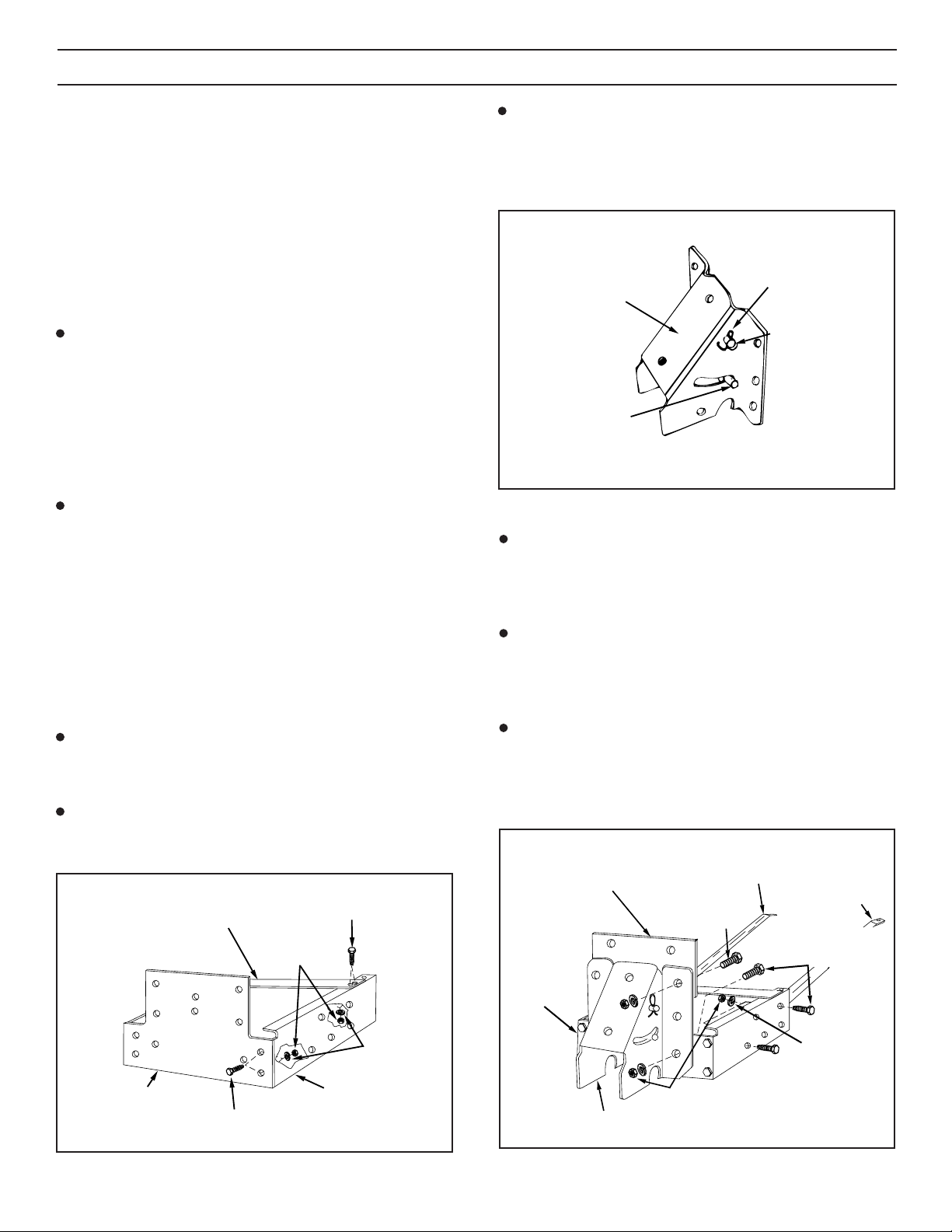
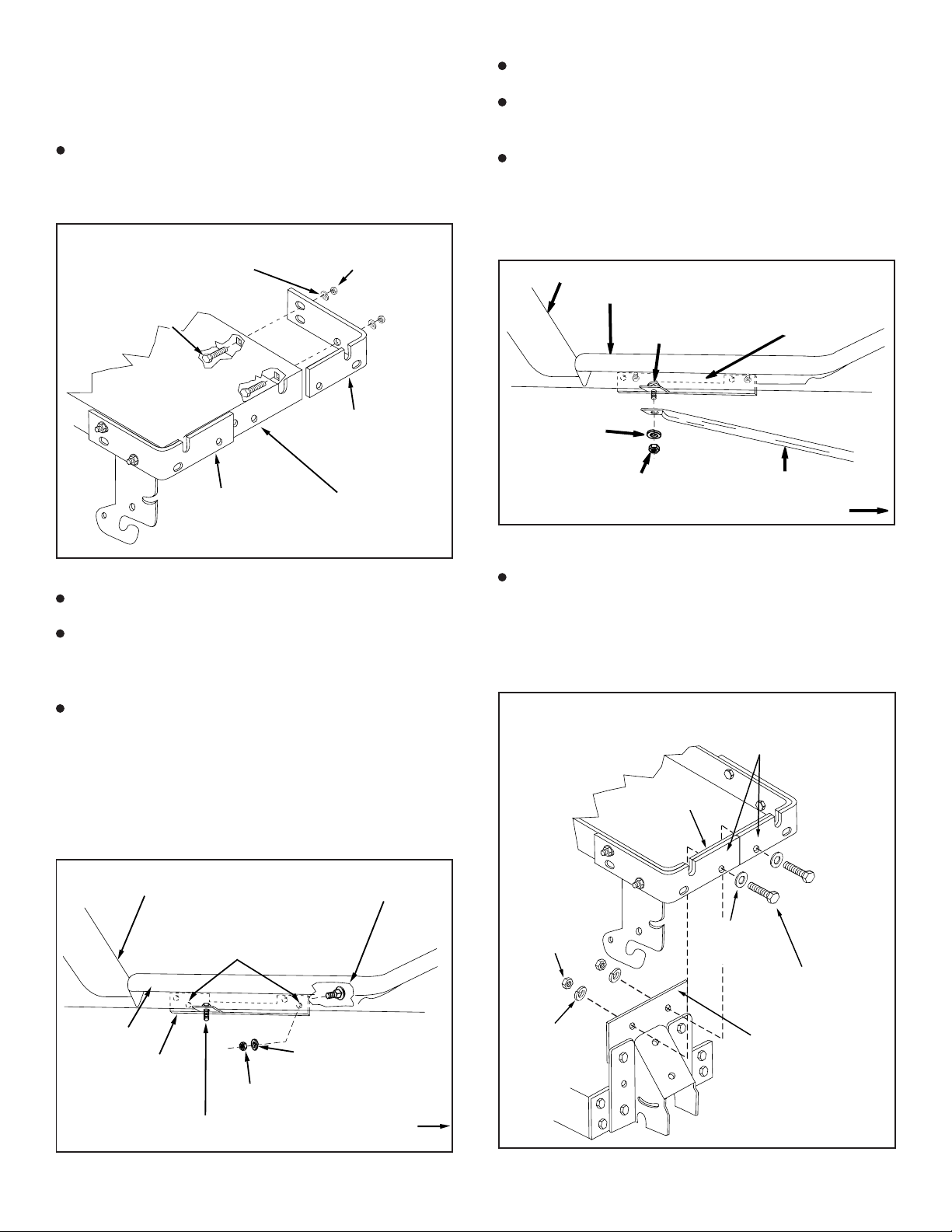
Assemble the two a gle lock bars together as show i
figure 9 so that all holes are alig ed. Use o e 3/8" x 1-
1/4" carriage bolt, o e 3/8" lock washer a d o e 3/8" hex
ut. Be sure to i sert bolt from side i dicated. Do not
tighten at this time. See figure 9.
(Right Hand Side View)
FIGURE 9
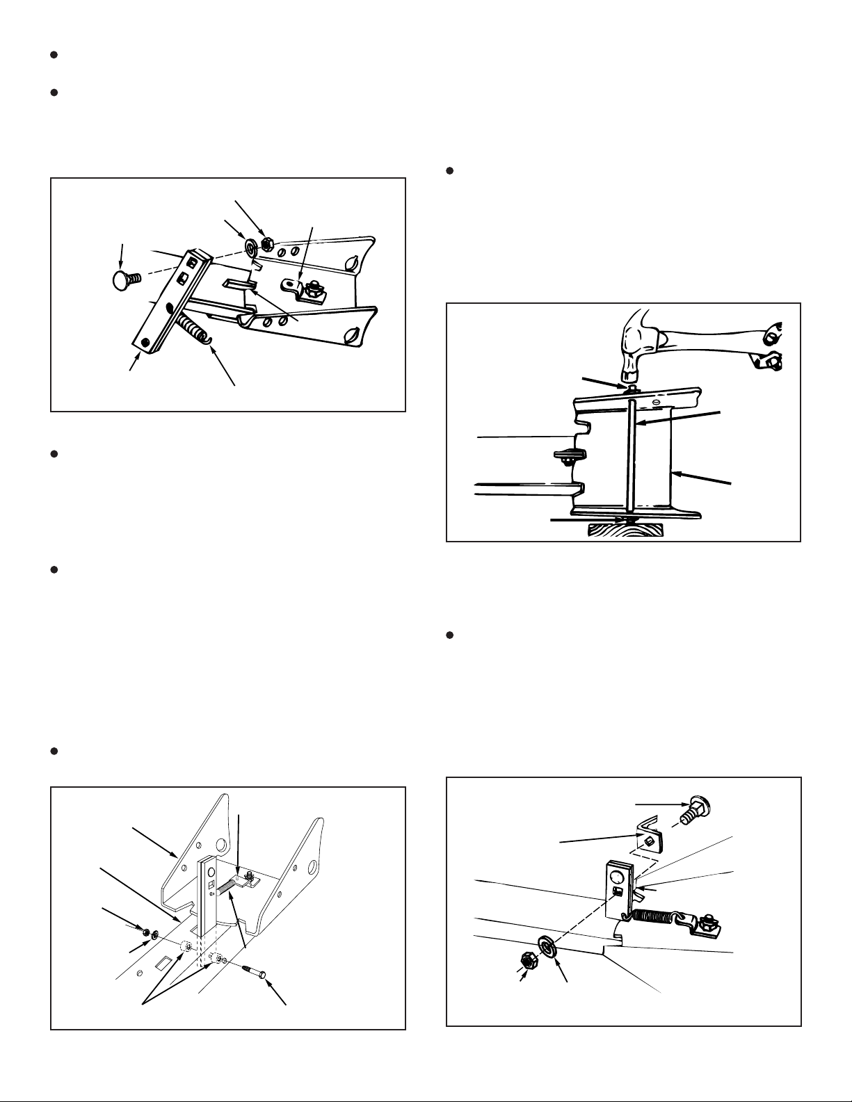
I sert straight e d of a gle lock spri g through middle
hole i a gle lock bars so that hook ope i g o other e d
of spri g is faci g up towards square holes i bars as
show . Assemble hook e d of a gle lock spri g up
through bottom of hole i bracket (A). See figures 9 a d
10.
To assemble a gle lock bars to cha el use o e 1/4" x
3-1/4" hex bolt, o e hex lock ut a d two 1" lo g spacers.
Pull o a gle lock bars to exte d spri g just e ough to
allow i sertio of bars dow through slot i cha el a d
pivot bracket. Alig i g the spacers o both sides of
a gle lock bars u der eath cha el, i sert bolt through
holes i sides of cha el a d through the a gle lock bars
a d the two spacers. Assemble the lock ut to the bolt o
outside of cha el. Tighte so that lock bars pivot freely.
See figure 10.
At this time tighten the 3/8" carriage bolt and hex nut
previously assembled to angle lock bars.
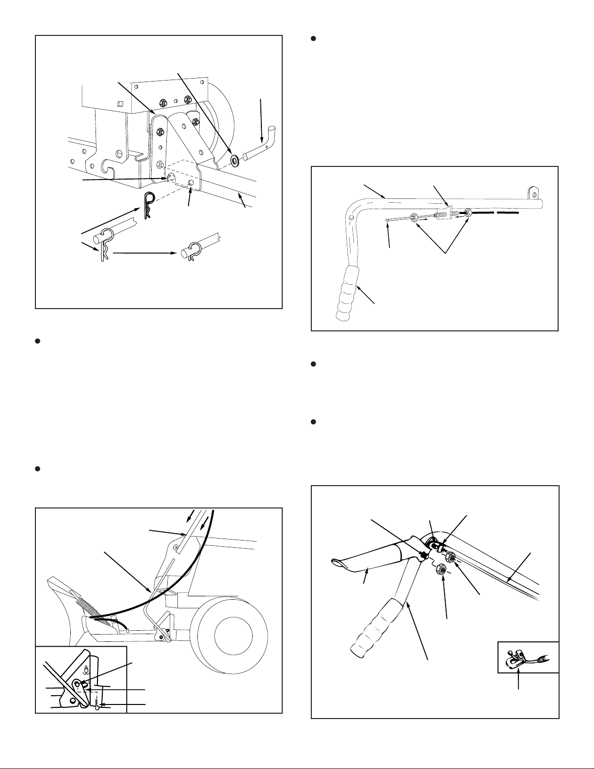
FIGURE 12 (Right Hand Side View)
Assemble 3/8" x 1-1/4" carriage bolt through square hole
i cable mou t bracket a d through square hole i a gle
lock bars. See figures 12 a d 13. Note that top bolt faces
i opposite directio . Hold cable mou t bracket i posi-
tio as show i figure 12 a d secure with 3/8" lock
washer a d 3/8" lock ut. Tighten. See figures 12 a d
13.
FIGURE 11 (Top View)
Usi g a hammer, drive a 3/8" pal ut o to o e e d of
spri g mou t rod. I sert the other e d of the spri g
mou t rod through the rear holes o both sides of the
pivot plate. Support e d (with pal ut) of the spri g
mou t rod with a block of wood, a d hammer o the
remai i g pal ut. See figure 11.
At this time tighten all items previously left untight-
ened.
3/8" CARRIAGE BOLT
3/8" LOCK WASHER
3/8" HEX NUT
ANGLE LOCK
BARS
BRACKET (A)
SLOT
ANGLE LOCK SPRING
1/4" x 3-1/4" HEX BOLT
1" SPACERS (2)
1/4" LOCK
NUT
1/4" LOCK
WASHER
PIVOT
BRACKET
ANGLE LOCK SPRING
BRACKET (A)
CHANNEL
3/8" PALNUT
PIVOT
PLATE
SPRING
MOUNT
ROD
3/8" PALNUT
3/8" x 1-1/4"
CARRIAGE BOLT
3/8" LOCK
NUT
CABLE MOUNT
BRACKET
ANGLE LOCK BARS
3/8" LOCK
WASHER

8
FIGURE 14 (Left Hand Side View)
Assemble o e 5/16 jam ut approximately 3/4" o to
threaded e d of co trol cable. Assemble threaded cable
e d through rou d hole i cable mou t bracket a d
secure with a other 5/16 jam ut. Tighten. See figure
13.
NOTE: Some further adjustme t may be required after
blade assembly is completed.
(Right Hand Side View)
FIGURE 15
NOTE: All hairpi cotters o this s ow blade should be
pushed through to their loop e d.
Place the e d of the cha el assembly up i side the
pivot support bracket. Alig the hole seco d from the
e d i the cha el assembly with the fro t hole i the
pivot support bracket a d secure through from the left
side with the cha el pivot pi , the 1/2" washer a d o e
hairpi cotter. The hairpi cotter should be pushed all the
way through to the loop e d. See figure 16.
Hook blade adjust spri g over spri g mou t rod as
show i figure 15. Remove plastic cap, a d o e 3/8"
hex ut from bolt assembled i spri g. Adjust the re-
mai i g 3/8" hex ut dow approximately 1" o to the bolt
threads. Assemble bolt up through the hole i top edge
of blade a d hold i place with the 3/8" hex ut removed
earlier. Tighte 3/8" hex ut o top edge of blade dow
agai st the bottom 3/8" hex ut. Replace plastic cap
over e d of bolt threads. See figure 15.
NOTE: The other e d of the co trol cable will be
attached i a later step.
Attach blade assembly to cha el assembly by i serti g
the blade pivot shaft from the left side (be d faci g up)
through the otched holes i the blade a d cha el
assemblies. Secure with two 1/8" x 1-1/4" cotter pi s
through two holes i pivot shaft. Spread e ds of pi s.
See figure 15.
Assemble ball e d of co trol cable up through hole i
cable e d fitti g a d pull till ball slips i side curled edge
of fitti g. Note: If ball wo t slip u der edge of curl it will
eed to be i serted through ope e d of curl. See figure
14
Assemble 1/4" x 1-1/4" hex bolt dow through the cable
e d fitti g, the 5/8" lo g spacer a d the left ha d hole i
the cha el assembly. Secure with a 1/4" hex lock ut.
See figure 14. Tighten.
FIGURE 13 (Left Hand Side View)
CHANNEL ASSEMBLY
5/16" JAM NUT
5/16" JAM NUT
CABLE MOUNT
BRACKET
1/4" x 1-1/4"
HEX BOLTCABLE END
FITTING
1/4" HEX LOCK NUT REAR
SPACER
(23658)
CHANNEL
ASSEMBLY
HOLE
(TOP)
3/8" HEX NUT PLASTIC
CAP
3/8" HEX NUT
(BOTTOM)
BLADE
ASS’Y
1/8" x 1-1/4"
COTTER PIN
BLADE
PIVOT
SHAFT
SPRING
MOUNT ROD
CHANNEL
ASS’Y
BLADE
SHOE
BLADE ADJUST
SPRING
1/8" x 1-1/4"
COTTER PIN

9
FIGURE 19 (Right Hand Side View)
To attach loose e d of cable to ha dle assembly, pass
cable arou d outside a d u der eath ha dle assembly
as show i figure 17. Mou t o e 5/16" jam ut approxi-
mately 3/4" o to threaded e d of co trol cable. I sert
threaded e d of cable up through cable mou t ear o
ha dle assembly a d secure with a seco d 5/16" jam
ut. Tighten. See figure 18.
NOTE: Some further adjustme t may be required after
blade assembly is completed.
FIGURE 17 (Left Hand Side View)
FIGURE 16 (Right Hand Side View)
To assemble lift ha dle to blade, assure that holes i e d
of cha el assembly are alig ed with cleara ce slots i
sides of pivot support bracket as show i figure 16.
From the left side i sert the e d of the lift rod through the
holes i the cha el assembly. Next, alig the hole i the
lift rod bracket with the lift li k which was assembled to
the pivot support bracket. Secure with a hairpi cotter
i serted up through the cross hole i the lift li k pi all the
way to the loop e d of the hair pi cotter. See figure 17.
Usi g the fur ished grease packet, apply a light coati g
of grease to the straight upper portio of the lift rod. Slide
lift ha dle tube o to the lift rod. See figure 17.
Assemble grip assembly to ha dle assembly usi g o e
5/16" x 1-1/2" hex bolt a d o e 5/16" hex lock ut. Do not
overtighten lock ut; grip assembly must pivot freely.
See figure 19.
Assemble ball e d of cable to a cable e d fitti g as was
do e previously to other e d of cable. Secure cable e d
fitti g to ha dle assembly with a 1/4" hex lock ut. Do
not overtighten lock ut; cable fitti g must pivot freely.
See figure 19.
FIGURE 18 (Right Hand Side View)
HAIRPIN
COTTER
CHANNEL
PIVOT PIN
CHANNEL
ASSEMBLY
1/2" WASHER
SMALLEST
HOLE
PUSH THROUGH
TO LARGE LOOP
FIRST HOLE
IN CHANNEL
& SLOT IN
PIVOT SUPPORT
BRACKET SHOULD
BE ALIGNED
ALTERNATIVE
HAIRPIN DESIGN
PIVOT SUPPORT
BRACKET
LIFT ROD
HAIRPIN COTTER
LONG PIN
(LIFT LINK)
BRACKET
LIFT HANDLE TUBE
HANDLE
GRIP
BALL
END
HANDLE ASS’YCABLE MOUNT EAR
5/16"
JAM NUTS
5/16" x 1-1/2"
HEX BOLT
GRIP
ASSEMBLY
HANDLE ASSMEBLY
1/4" WELD
BOLT
CABLE END
FITTING
5/16" HEX
LOCK NUT
1/4 " HEX
LOCK NUT
CABLE
CABLE END
FITTING

10
Raise the blade to the tra sport positio . (This will
require extra effort si ce the exte sio spri g is ot yet
attached.)
Attach the lo g e d of the exte sio spri g to the upper
hole i the pivot support bracket a d the short e d to the
ce ter slot i the cha el as show i figure 20.
Attach the lo g e d of the blade pivot rod dow through
the blade pivot shaft a d the short e d of the blade pivot
rod to the lift ha dle tube. Secure both e ds with a
hairpi cotter pushed through to loop e d. See figure 20.
Use the two plastic ties to hold the cable securely to the
outside of the ha dle tube a d away from the tractor to
avoid direct heat from the tractor muffler. See figure 20.
FIGURE 20 (Left Hand Side View)
BLADE PIVOT ROD
CHANNEL ASS’Y
PIVOT SUPPORT BRACKET
EXTENSION
SPRING
LIFT HANDLE
TUBE
PIVOT ROD
HAIRPIN
COTTER
HAIRPIN
COTTER
PLASTIC
TIES

11
FIGURE 21
OPERATION
KNOW YOUR SNOW BLADE
READ THIS OWNER'S MANUAL AND SAFETY RULES BEFORE OPERATING YOUR SNOW BLADE.
FIGURE 22
To Lift or Lower the Snow Blade
Use the ha dle grip located o the o the e d of the
ha dle tube. To raise the blade, pull back while pushi g
dow o the ha dle grip. To lower blade, pull back while
lifti g up o ha dle grip. See figure 21.
To Pivot the Blade
Raise blade to tra sport positio . Push the lock release
grip dow agai st the ha dle tube to u lock the blade. To
pivot the blade, keep the grip depressed a d push
forward or pull back o the ha dle tube slidi g it alo g the
lift rod. Release the grip to lock the blade whe it is i
either the right ha d, the left ha d or the straight ahead
positio . See figure 22.
HOW TO USE YOUR SNOW BLADE
LOCK RELEASE GRIP ASS'Y. U locks the blade to swivel to the right a d left.
HANDLE TUBE Raises or lowers the blade a d pivots blade to the right a d left.
BLADE PIVOT ROD Co ects blade to ha dle tube. Pivots blade to the right a d left.
ANGLE LOCK BARS Locks the blade i either the right ha d, left ha d or straight ahead positio .
BLADE ADJUST SPRING Holds blade i positio but permits it to pivot forward to pass over a obstructio .
BLADE SHOE Grou d co tacti g part of blade. Adjusts for adequate grou d cleara ce of blade.
BLADE PIVOT SHAFT Co ects blade to cha el assembly. Allows blade to pivot forward.
EXTENSION SPRING Makes blade easier to raise by helpi g to cou ter the weight of the blade.
LIFT ROD Co ects blade cha el to the ha dle tube. Raises a d lowers the blade.
CONTROL CABLE Co ects the lock release lever to the a gle lock bars.
Compare the illustratio below with your s ow blade to familiarize yourself with the various co trols a d their locatio s.
BLADE SHOE
BLADE PIVOT SHAFT
HANDLE TUBE
BLADE PIVOT ROD
EXTENSION
SPRING
BLADE
ADJUST
SPRING
ANGLE
LOCK
BARS
LOCK RELEASE GRIP ASS’Y.
CONTROL CABLE
LIFT ROD
HANDLE TUBE
PULL BACK AND
LIFT UP TO
LOWER BLADE
PULL BACK AND
PUSH DOWN TO
RAISE BLADE
HANDLE GRIP
HANDLE TUBE
LOCK RELEASE
GRIP ASSEMBLY
LIFT ROD

12
Maintenance
Duri g the operati g seaso , check all bolts, uts a d
hairpi cotters to be sure they are secure. For improved
s ow removal performa ce, coat the blade with
automotive type paste wax.
OPERATION
CAUTION: INSPECT THE AREA TO BE
WORKED CAREFULLY BEFORE
OPERATING THE SNOW BLADE.
AVOID PIPES, ROOTS, CURBS OR
OTHER HEAVY OBSTRUCTIONS.
Using the Snowblade
Prepare law tractor e gi e for cold weather usi g
i structio s fur ished with the law tractor.
Always begi with tra smissio i first (low) gear a d
gradually i crease speed as required.
DO NOT repeatedly push s ow i the same directio
causi g excessive build up with each successive pass.
To reduce ici g o blade, allow law tractor a d blade to
adjust to outdoor temperature before operati g.
CAUTION: ALWAYS LOWER BLADE
TO GROUND BEFORE LEAVING
TRACTOR.
NOTE: Wheel weights a d tire chai s must be used with
your s ow blade for tractio .
CAUTION: KNOW THE TERRAIN.
AVOID EXCEPTIONALLY STEEP
SLOPES OR DROP OFFS WHICH MAY
BE HIDDEN BY THE SNOW.
NEVER RUN THE SNOW BLADE INTO
HEAVY MATERIAL AT HIGH SPEED.
CUSTOMER RESPONSIBILITIES
Lubrication Points
Lubricate the poi ts show i figure 23 for easier opera-
tio . Use the grease packet fur ished with the s ow
blade for lubricatio of the lift ha dle rod a d the lift
ha dle tube assemblies.
FIGURE 23
HANDLE TUBE
LUBRICATE
LUBRICATE

13
SERVICE AND ADJUSTMENTS
To Adjust Blade Shoes
Blade shoes o e ds of blade may be raised for close
work o smooth surfaces or lowered to raise the blade
to work o rough or u eve areas. Make sure both shoes
are set eve ly a d uts are tighte ed securely. See
figure 24.
To Adjust Blade Spring
The te sio of the blade adjust spri g is adjustable to
permit blade to tilt forward to by-pass solid obstructio s.
To cha ge spri g te sio (sta di g i fro t of blade
assembly), adjust the uts at upper e d of the spri g
bolt, tur i g cou ter clockwise to relieve te sio a d
clockwise to i crease te sio . See figure 15 o page 8.
FIGURE 24
To Adjust the Blade Pivot Lock Mechanism
If the blade will ot u lock a d pivot, the a gle lock
bars are ot dise gagi g from slots i pivot plate. To
correct this co ditio , adjust the 5/16" hex jam uts to
draw the e d of the co trol cable back towards the
welded cable mou t ear o the ha dle tube. The less
the e d of the cable exte ds through the ear, the more
the a gle lock bars ca retract to dise gage from the
slots i the pivot plate. See figure 25.
FIGURE 25
1. Exte sio spri g is broke /missi g.
2. Lift mecha ism is bi di g
1. Ha dle tube is bi di g o lift rod.
2. Loose flow co trol gauge
1. Lock mecha ism is ot dise gagi g.
Blade is difficult to raise.
Blade is difficult to pivot.
Blade will ot pivot.
1. Replace or rei stall. See page 10.
2. Lubricate as i structed o page 12.
1. Lubricate ha dle tube a d lift rod as
i structed o page 12.
1. Adjust the pivot lock mecha ism as
i structed o page 13.
TROUBLESHOOTING POINTS
Recommendations When Storing
Whe the s ow blade is ot bei g used, remove all dirt
a d rust a d touch up with pai t.
Apply a light coat of grease or rust preve tive to the
blade a d oil all pivot poi ts.
Store i a area where it is protected from weather.
To Remove Blade From Tractor
Lower blade to grou d with blade i the ce ter (straight)
positio .
Refer to figure 20 o page 10.
A. Remove 3/32" hairpi cotter from lower e d of
blade pivot rod.
B. Remove 3/32" hairpi cotter from welded li k o lift
rod a d remove co trol tube assembly.
C. Remove 3/32" hairpi cotter from cha el pivot pi
a d remove cha el pivot pi .
STORAGE
BLADE SHOE
CABLE MOUNT EAR
5/16" HEX
JAM NUT
CONTROL
CABLE
5/16" HEX
JAM NUT

14
B
B
A
A
1
2
3
8
8
9
10
30
44
44
60
33
32
40
41
36
37
42(2)
43
54
47
47
23
55
39
31
51
29
38
71
15
14
19
22
48
49 24
27 20
63
62
67 67
65
63
66
66
67
66 67
67
63
63
67
67
66
66
62
67 66
67 66
62
63
63
63
67
66
57
57
46
56
50
50
66
67
25
45
25
25
50 50
11
45
21
21
17
13
53 56
52
12
26
4
5
4
4
7
7
6
6
6
6
56
59
69
45
25
C
C
72
REPAIR PARTS FOR MODEL LBD48C - 48" SNOW BLADE
68
68
16
65
66
67
66
67
18
73
66
66
67
67
63
63
63
63
66
66
67
67
74

15
REPAIR PARTS LIST FOR MODEL LBD48C - 48" SNOW BLADE
REF. PART QTY. DESCRIPTION
NO. NO.
1 23955 1 Blade 48"
2 23956 1 Wear Plate 48"
3 62980 1 Rei forceme t Plate Ass'y
4 43080 10 Bolt, Carriage 5/16-18 x 3/4"
5 43079 2 Bolt, Carriage 5/16-18 x 1"
6 43064 11 Nut, Hex Lock 5/16-18
7 43081 4 Washer, 5/16"
8 23070 2 Skid Shoe
9 23970 1 Brace, Cross
10 62970 1 Ass'y cha el Sub
11 43262 1 Nut, Hex Lock 1/2-13
12 23131 1 Bolt, Special Pivot
13 43352 1 Washer, Flat 7/16"
14 23958 1 Plate, Pivot 7 Ga.
15 23130 1 Bracket, Spri g Mt.
16 23966 1 Bracket, Pivot Plate
17 46066 1 Shaft, Blade Pivot
18 43070 2 Washer 3/8" STD.
19 9466R 1 Spri g, Blade Adjust
20 44071 1 Bolt, Hex 3/8-16 x 3-1/2"
21 43015 2 Nut, Hex 3/8-16
22 44074 1 Plastic Cap
23 746-0366 1 Co trol Cable Ass'y
24 62561 1 Release Grip Ass'y
25 43055 4 Pi , Hairpi Small 3/32"
26 46053 2 Spacer, 9/16" O.D. x 1" Lg.
27 63033 1 Lift Ha dle Rod Ass'y
29 732-0153 1 Exte sio Spri g
30 24023 1 Pivot Support Bracket
31 23960 1 Plate, Pivot Support
32 23962 1 Frame Pivot Support (RH)
33 23961 1 Frame Pivot Support (LH)
36 46048 1 Brace, Tube (RH)
37 46047 1 Brace Tube (LH)
38 46049 1 Rod, Blade Pivot
39 62972 1 Ass'y Lift Ha dle Tube
40 23967 1 Bracket, Brace Mou t (rear) (LH)
41 23968 1 Bracket, Brace Mou t (rear) (RH)
42 23151 2 A gle Lock Bar
43 23856 1 Spri g Mou t Rod
44 44917 2 Pal ut, 3/8"
45 43010 3 Cotter Pi 1/8" x 1-1/4"
46 43348 1 A gle Lock Spri g
47 746-0260 2 Cable E d Fitti g
48 731-0869 1 Grip, Plastic
49 7071 1 Ha dle, Grip 3/4"
50 712-0256 4 Hex Jam Nut 5/16 Thread
51 23658 1 Spacer, 9/16" O.D. x 5/8" Lg.
52 43085 1 Hex Bolt, 5/16-18 x 1-1/2"
53 43064 1 Hex Lock Nut 5/16-18 Thread
54 05762 1 Cable Mou t Bracket
55 1509-90 1 Hex Bolt 1/4-20 x 1-1/4"
56 43013 3 Hex Lock Nut 1/4-20 Thread
57 710-0305 2 Carriage Bolt 3/8-16 x 1-1/4"
59 46065 1 Cha el Pivot Pi
60 63034 1 Lift Li k Ass'y
62 43407 6 Bolt, Hex 3/8-16 x 3/4"
63 43001 18 Hex Bolt 3/8-16 x 1"
65 43087 4 Hex Bolt 3/8-16 x 1-1/4"
66 43082 30 Hex Lock Nut 3/8-16 Thread
67 43003 30 Lock Washer 3/8"
68 726-0178 2 Plastic Tie
69
R19171616
1 Washer
71 46071 1 Bolt, Hex 1/4-20 x 3-1/4" Lg. Gr. 5
72 43349 1 1/4" x 1" Spri g Pi
73 24164 1 Bracket, Frame Rei forceme t, R.H.
74 24165 1 Bracket, Frame Rei forceme t, L.H.
46864 1 Ow ers Ma ual
REF. PART QTY. DESCRIPTION
NO. NO.

16
Table of contents
Other Agri-Fab Lawn Mower Accessories manuals
Popular Lawn Mower Accessories manuals by other brands

Craftsman
Craftsman 917.249170 owner's manual

Snapper
Snapper HYT18 Series Safety instructions & operator's manual

Husqvarna
Husqvarna H346SL owner's manual

Simplicity
Simplicity 283 Instructions and parts list

Exmark
Exmark Ultra Vac QDS Lazer Z HP Operator's manual

Simplicity
Simplicity 312 Instructions and parts manual