Ae-man-321-0.0 v1.1 TECHNICAL MANUAL
HEADQUARTER OFFICE & FACTORY: C/ Julián Camarillo, 26 28037 – MADRID (SPAIN)
Phone.:+34 91 754 55 11 www.aguilera.es
2
l detector have been installed apply power supply to the loop.
AUTIONS.
To prevent detector from dirty effect and warranty cancellation, detector
ete protection
or because paint can close air entry holes and then detector operation will be affected.
ESTING.
etectors must be tested after installation and following periodic maintenance.
efore testing, notify to the proper authorities that the detector system is undergoing maintenance, and be sure that all required functions related
Check that when you remove each detector from the base the fire alarm panel will be move announcing zone fault notice. If no any fault is
tor non-operation
moke sample from a test smoke aerosol to each detector during at least 10 seconds to activate the detector-sensing
Heat sen
detector to a flow of warm air at a temperature of between 65ºC and 80ºC from a distance of several centimeters. The
If a remo e light activated. If lighting activation does not arrive checking for wiring and well
er selected detector placed at the same detection loop, first at all you shall
ll detectors not capable to perform testing as above indicated must be replaced for technical service attendance.
fter testing implementation the alarm emergency exit, extinguishing system and automatic extinguishing shoot in functions cancelled previously
ETECTOR MAINTENANCE GUIDELINE.
he recommended minimum requirement for detector maintenance consists of an annual cleaning of dust from the detector head using a vacuum
o not attempt to disassemble factory sealed detector head. Opening the detector head the detector warranty will be void.
PECIFICATION.
C:Power Supply 15 ~ 35 Vdc
tur ambient dry temperature.
nsing.
by: Leds flashing once every 3~5
Alarm: Continuous red lighting from LEDs
Remote alarm output, rate:
Cover Height with base: 46 mm + 15mm heat sensor.
Installing the head
1º ALING WITH SHORT MARK
AND PLACE THE DETECTOR
INTO THE BASE
2º TWIST CLOCKWISE
TO ALIGN WITH TWO
LONG MARKS
BASE DETECTOR
HEAD DETECTOR
Align the components as show in the Figure.
Mate the detector head into the base and twist clockwise to secure it.
In case that detector head is not matching marks with the base the
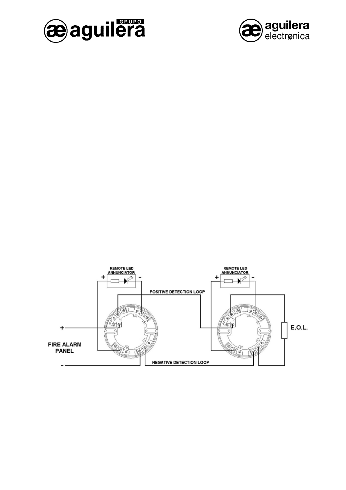
detector will operate but connection polarity of remote LED annunciator
are changed and then it is not assured its well performed operation.
The maximum number of detectors installed in the same loop is 30 units.
After al
C
must remain covered until the area is clean and dust free.
Detector protection cover is not intended to provide compl
against dust ambient pollution, therefore detector should be removed
before beginning to made masonry works, inner space revamping or
other dust producing activity.
Do not paint any part of detect
Detector protection cover must be removed before fire detection system can be made operational.
T
D
B
to alarm emergency exit, extinguishing system and automatic extinguishing shoot in are cancelled.
coming then recheck that there are not placed 2 wires or more at the same detectors base clamp at the terminal block.
Check to see if the indicator green LED is flashing every 3~5 seconds. If green LED fails to flash, it indicates the detec
condition or a faulty wiring is made.
Smoke sensor testing:
• Apply some s
chamber. When sufficient smoke portion has entry within the chamber then detector will generate an alarm signal being
recognized externally by a continuous lighting from two external LEDs and fire alarm panel shall be in alarm mode.
sor testing:
• Subject the
detector should alarm within 30 seconds.
te LED annunciator is coupled then also shall b
done detector plug-in into base is required to be done it again
To made same detector testing as above mentioned for anoth
reset the loop by switching-off from the remote fire alarm panel and also check the zone is in stand-by mode before start-up with the next
one detector checking.
A
A
at the fire alarm panel shall be activate and proper authorities shall be informed that the fire alarm system is again in operation.
D
T
cleaner. All ambient head detector entry holes shall be keeping totally cleaned from ambient entry obstacles. For an exhaustive clean treatment
the detector head should be send to AGUILERA ELECTRONICA, Customer Assistance Department.
D
S
D
0832
0832-CPD-0207
EN 54-7:2000 - EN 54-5:2000
LPCB Nº 512b/02
Standby current: 35 µA
Alarm current: 70 mA max.
Loop Wires sizes: 2 X 1.5 mm2
Operating Tempera e Range: 10ºC a +50º C
Operating Humidity Range: 10% al 90% Relative Humidity, Non-conde
Start-up Time (Max.): 60 s
Lighting Annunciators: Stand
seconds.
Remote LED annunciator, 6 Vdc.
Detector Dimensions: Cover : 99 mm. (Diameter)
Raw Material: White ABS plastic.