Ahlborn Almemo V5 8990-1 User manual

Operating Instructions
Intelligent Transmitter
ALMEMO®8990-1
V1.0
03.09.1999
AHLBORN Mess- und Regelungstechnik GmbH
Eichenfeldstraße 1-3 · D-83607 Holzkirchen
Tel.+49(0)8024/30070 · Fax +49(0)8024/300710

Operating Instructions
Intelligent Transmitter
ALMEMO®8990-1
For Reference with the ALMEMO®Manual
Table of Contents
Page
1 Introduction 3
1.1 Function Range 3
1.2 Operating Controls 7
2 Initial Operation 8
3 Power Supply 9
3.1 Plug-In Power Supply Unit 8
3.2 DC Voltage Supply 8
3.3 Data Buffer 8
3.4 Sensor Voltage Supply 8
4 Connection of the Transducers 10
4.1 Transducers 10
4.2 Measuring Inputs and Additional Channels 11
5. Analogue Output 12
5.1 Scaling and External Control 12
5.2 Response Time 12
5.3 Selecting the Measuring Channel 12
6. Data Acquisition 13
6.1 Digital Interfaces 13
6.2 Cyclic Measuring Point Scan of One Device 14
6.3 Cyclic Measuring Point Scan of Networked Devices 14
6.4 Data Acquisition via Software 15
7. Troubleshooting 16
8. Electromagnetic Compatibility 17
Appendix
Technical Data 18
Product Overview 18
Your Contacts 19
2 ALMEMO8990-1
Table of Contents

1. INTRODUCTION
The transmitter ALMEMO®8990-1
Version 5
is an instrument from the
unique product range of measuring devices that are all equipped with the
ALMEMO®connector system, which has been patented by Ahlborn GmbH. The
intelligent ALMEMO®connector provides important advantages with regard to
the connection of sensors and peripherals as all parameters are stored in an
EEPROM within the connector. As a result, the programming that usually has
to be performed for the connection is not required.
All sensors and output modules can be connected to all ALMEMO®measuring
devices in the same way. The operation and programming is identical with all
units. Therefore, all of the ALMEMO®measuring system items listed below are
described, in detail, in a separate ALMEMO®manual that is supplied with every
device:
Detailed description of the ALMEMO®system (manual section 1)
Overview of the device functions and measuring ranges (manual section 2)
All sensors with basic principles, operation, technical data (man. section 3)
The options for connecting existing sensors and electr. signals (man.sect. 4)
All analogue and digital output modules (manual section 5.1)
The interface module RS232, fiber optics, Centronics (manual section 5.2)
The entire ALMEMO®networking system (manual section 5.3)
All functions and their control via the interface (manual section 6)
A complete interface command list with all print outputs (manual section 7)
These operating instructions, therefore, only cover features and controls that
are specific for a certain device. As a result, the sections dealing with the
system control via keyboard will only often provide a note referring to a more
detailed description within the manual (manual section x.x.x).
1.1 Function Range
The transmitter ALMEMO®8990-1 has a ALMEMO®measuring input with up to
4 measuring channels. One alarm contact is integrated as standard equipment;
one electrically isolated analogue output is available as an option. Furthermore,
the two output sockets allow for connecting any ALMEMO®output modules, for
example, digital interface, analogue output, trigger input or external relays.
Several devices can be networked by a simple connection between the devices
via network cable or with an optional RS485 interface. The programming can
be performed via the ALMEMO®connectors or serial interface.
SENSOR PROGRAMMING
The measuring channels are automatically programmed by the ALMEMO®
connectors of the sensors. However, the user can easily complete or modify
the programming via interface by using the software AMR-Control, without
affecting the measuring process.
ALMEMO8990-1 3
Functions

Measuring Ranges
There are corresponding measuring ranges for sensors with a non-linear
characteristic such as 10 thermocouple types, Ntc and Pt100 sensors, infrared
sensors, and flow sensors (rotating vanes, thermoanemometers, pitot tubes).
Humidity sensors are available with function channels that also calculate
humidity data such as dew point, mixture ratio, vapour pressure and enthalpy.
Even complex chemical sensors can be used. The acquisition of measured
data from other sensors is easily possible by using voltage, current and
resistance ranges with individual scaling in the connector. Existing sensors can
be used without problems. Only the corresponding ALMEMO®connector has to
be connected using its terminals. Furthermore, adapter connectors with an
integrated microcontroller are available for frequencies and pulses. This way,
nearly all sensors can be connected to any ALMEMO®measuring instrument
and are interchangeable without requiring any settings.
Function Channels
Maximum, minimum, average values and differences of two measuring
channels can be programmed as function channels and can be processed and
printed like normal measuring points.
Dimension
The 2-digit dimension can be altered for each measuring channel so that the
printout will always indicate the correct dimension, for example, when a
transmitter is connected. The conversion from °C to °F is automatically
performed according to the dimension.
Name of Measured Values
Sensors can be identified by a 10 digit alphanumeric designation. It is entered
via the interface and appears on the printout or display if the evaluation is done
via PC.
Correction of Measured Values
For correcting measured values a zero point and slope (gain) correction can be
applied to the measured value of each measuring channel. This also allows for
sensors to be interchanged that usually, at first, require an adjustment
(expansion, force, pH).
Scaling
The base value and the factor allow for a further scaling of the corrected
measured value of each measuring channel for zero point and slope (gain).
The decimal point position can be set by the exponent.
4 ALMEMO8990-1
Functions

Limit Values and Alarm
Two limit values (1 Max and 1 Min) can be set for each measuring channel. If a
limit value is exceeded a signal lamp will be on and the internal alarm contact
responds. The alarm contact can also be individually allocated to the limit
values. An alarm value printout can be performed as required. As a standard,
the hysteresis is set to 10 digits. However, it can also be adjusted from 0 to 99.
Sensor Locking
All sensor data stored in the EEPROM of the connector can be protected
against undesired access by means of a graded locking function.
MEASUREMENT
Up to 4 measuring channels are available for each transducer, i.e. it is also
possible to evaluate double sensors, individually scaled sensors, or sensors
with function channels. The selected measuring point can be scanned with a
conversion rate of 2.5 or 10 measurements/second and the measured value is
provided as output to the analogue output, if available.
Measured Value
A continuous presentation of the measured value from the selected measuring
point is provided and also includes automatic zero point correction and optional
correction of the measured value or new scaling. Most sensors will provide
automatic sensor breakage recognition (exception: connectors with shunt,
dividers or auxiliary electronics).
Measuring Functions
Special measuring functions are required for some sensors in order to achieve
an optimal acquisition of measuring data. Cold junction compensation is
performed at thermocouples. Temperature compensation is performed at
dynamic pressure and pH and conductivity probes and atmospheric air
pressure compensation is performed at humidity sensors, dynamic pressure
sensors and O2sensors. With infrared sensors the parameters zero point and
slope correction are used for background temperature and emissivity factor.
Max and Min Value
Each measurement involves an acquisition and storing of the maximum and
minimum value. These values can be displayed, printed or cleared.
ANALOGUE OUTPUT and Scaling
On request the transmitter can be equipped with an electrically isolated
analogue output with a 15bit/32,500digit resolution (-1.2500...+2.0000V,
-6.250...+10.000V or 0/4.000-20.000mA). By means of analogue start and
analogue end the indicated measured value can be scaled so that the resulting
measuring range covers the full standard range (0-2V, 0-10V or 0/4-20mA).
ALMEMO8990-1 5
Functions

PROCESS FLOW PROGRAMMING
A cyclic measuring point scan with a time-based process flow control is
required to register the measuring data of all measuring channels. If only one
transmitter is available, the measuring point scans can be performed with an
own time control. For this purpose the print cycle, measuring cycle and, if fast
speed is required, the conversion rate is available. The measurement can be
started and stopped by using the interface, an external trigger signal or an
exceeding of limit values. If several modules or devices are networked, the
process control must be performed via an external CPU, which can either be in
an ALMEMO®5590-3 system or a PC with data acquisition software.
Time and Date
The time and date or the pure measuring time is used for an accurate
recording of the measurement.
Print Cycle
The print cycle is programmable between 1s and 59h/59min/59s and provides
a cyclic output of measured values to the interfaces or memories and also
provides a cyclic averaging.
Measuring Cycle
The measuring cycle, also programmable between 1s and 59h/59min/59s, is
for a cyclic scanning with limit value monitoring, alarm message, output of
alarm values and averaging.
Average Value
The measured values that result from scanning the measuring points can be
averaged as desired either over the total measuring time or over print cycle
time. Function channels are provided for a cyclic output of average values.
Conversion Rate
With ALMEMO®V5 devices, all measuring points can be continuously scanned
with the conversion rate (2.5 or 10 meas./s). It is possible to output all
measured values via the interface.
Control Outputs
The internal alarm contact or up to 4 external output relays and an analogue
output can be individually triggered via the interface.
6 ALMEMO8990-1
Functions

Output
All data logs and all stored measured values and programmed parameters can
be provided as output to any peripheral equipment via interface. Interface
cables for RS232 or Centronics interfaces are available. An electrically isolated
RS485 interface can be integrated as an option. The output of measuring data
can be selected in list format, columns or spreadsheet format. Files in
spreadsheet format can be directly processed by any spreadsheet software.
The print header can be programmed specifically to the company or
application.
Networking
All ALMEMO®devices can be addressed and can be easily networked by a
simple connection with network cables or network junctions for longer
distances.
SOFTWARE
The AMR-Control software, which allows for the entire programming of the
sensors, the configuration of the measuring instrument and the read-out of the
data memory, is supplied with each ALMEMO®manual. The integrated
terminal also allows for online measurements. The WINDOWS®software
packages, Win-Control and DATA-Control, are available for data acquisition of
networked devices, graphical presentation and complex data processing.
ALMEMO8990-1 7
Operating Controls

1.2 Operating Controls
POWER SUPPLY (1)
12V miniature socket for 12V plug-in mains adapter ZB 3090-NA
(2) 12V + -option U: terminal connector 10 to 36 V DC electr. isolated
(3) ON control lamp for power supply is available
(4) ALARM alarm lamp for ´limit value exceeded´, sensor breakage
(5) S-C-Ö solid-state relay 50V, 100mA (make, common, break)
(6) ANALOGUE OUTPUT
2V -+ option R1: -1.25 to 2 V electrically isolated
10V -+ option R2: -6 or 0 to 10 V electrically isolated
20mA -+ option R3: 0 or 4 to 20mA electrically isolated
DIGITAL OUTPUTS
(7) 00 to 99 2 code switches for setting the device address
(8) A B Y Z option I: RS485 interface electrically isolated
(9) A1 ALMEMO®socket for
V24 interface with cable ZA 1909-DK
V24 interface with fiber optics (ZA 1909-DKL)
(10) A2 ALMEMO®socket for
networking with network cable ZA1999-NK
analogue output not electr. isolated with cable ZA 1601-RK
trigger input (ZA 1000-EK/ET)
alarm outputs (ZA 1000-EGK)
MEASURING INPUT
(11) M ALMEMO®socket for all ALMEMO®sensors
M1 to M3 additional channels for double sensors, function channels
8 ALMEMO8990-1
Operating Controls
M
®
A2 A1
8990-1
S C +12 GND
ALARM
RS485 20 mA
ON
Ö
01
2
3
4
5
6
7
8
901
2
3
4
5
6
7
8
9
ABCD
+
11
10
9
47
3
1
2
568

2. INITIAL OPERATION
1. Connect the transducer to the socket M (11), see 4.
2. For power supply connect the mains adapter to socket 12 V (1), see 3.
3. Connect the recording device to the analogue output (6).
4. Connect the alarm device to the terminal connector (5).
5. Communication with a computer
Connect computer via interface cable to socket A1, see manual 5.2.
Set interface to 9600 bd, 8 data bits, 1 stop bit, no parity.
Program the measuring range, see manual 6.3.3.
Enter the limit values, see manual 6.3.9.
Set the analogue output range, see manual 6.10.7.
Scan measured values, see manual 6.5.
3. POWER SUPPLY
3.1 Plug-In Power Supply Unit
As a standard, the power supply is provided via a 12V plug-in power supply unit
(ZB 3090-NA). It has to be connected to the 3-pole miniature socket (1) and
locked by one rotation. Alternatively, it is also possible to connect another 12V
supply to the terminal screw clamp (2).
3.3 DC Voltage Supply (Option U)
The option U (OA 8990-U) is available if an electrically isolated DC voltage
supply is required (10 to 36V). The voltage must be connected via a terminal
screw clamp to socket (2) of the device. The measuring instrument can be
operated with 12V and 24V voltage supply equipment.
3.4 Data Buffer
The programming parameters of the sensors are stored in an EEPROM within
the connector. The calibration and the process flow control are stored in an
EEPROM within the device and will be buffered when the system is switched
off. However, the time and date will always be set to zero when the system is
being switched on.
3.5 Sensor Voltage Supply
With all power supplies a sensor voltage supply of 12V DC (70mA at max.) is
available at the terminals - and + of the ALMEMO®connector. Only with a few
special connectors (e.g. ZA 9050-FSx) this voltage is regulated to 5V.
ALMEMO8990-1 9
Initial Operation

4. CONNECTION OF THE TRANSDUCERS
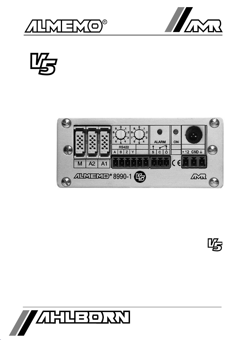
Any ALMEMO®sensors can be easily connected to the ALMEMO®input socket
M (11). For connecting existing sensors with open ends it is only necessary to
connect a corresponding ALMEMO®connector.
The connection of the sensors should be performed very thoroughly as it can
have large effects on the electromagnetic compatibility. Although the
measuring input is electrically isolated from the outputs, it is advisable to
isolate the transducer when installing because the protective earth connection
and the housing can often provide high voltage transients in industrial
environments. When performing the cabling it must be considered that the
leads are not wired near magnetic valves, contactors and motors and that they
are not guided together with leads for such devices. The leads should be as
short as possible and should have a cross section of 0.5 mm² at minimum (1.0
mm² at max.). Furthermore, electromagnetic influences can be reduced by
twisting the lines or by guiding cables in steel tubes. Electrostatic disturbances
can be avoided by using shielded cables. The metal braid shield is then
connected to the ´-´ terminal of the connector.
4.1 Transducers
A detailed description of the comprehensive ALMEMO®sensor range and the
connection of existing sensors to the ALMEMO®instruments are provided in
the ALMEMO®manual (s. man. sect. 3 and 4). All standard sensors with
ALMEMO®connector usually have the measuring range and dimension already
programmed and can be immediately connected to any input socket. A
mechanical coding ensures that sensor and output modules can only be
connected to the correct sockets. Furthermore, each ALMEMO®connector has
two locking levers that snap in when the insertion into the socket is established
and that prevent a disconnection caused by pulling the cable. Both levers must
be pressed on the sides for disconnecting the connector.
The programming of the sensor connectors can, with the transmitter
ALMEMO®8990-1, only be changed via the serial interface (see man. section
6). However, this can be carried out by using the PC and the configuration
software AMR-Control or any terminal application (e.g. Windows Terminal) and
using very simple commands. Due to the data storage within the connector, it
is also possible to perform the programming with any of the ALMEMO®
instruments, which are equipped with a keyboard. The sensor connector must
be connected to the selected channel. When programming, it must be
considered that factory-programmed parameters are, by a locking mode,
protected against unintentional modification and that the locking level must first
be reduced before desired changes can be performed. The connectors ZA
9000-FS are not locked and are, therefore, most suitable for programming by
the user.
10 ALMEMO8990-1
Connection of the Transducers

4.2 Measuring Inputs and Additional Channels
The transmitter ALMEMO®8990-1 has one input socket (11) with measuring
channel M0. However, ALMEMO®sensors can, if required, provide up to 4
channels so that a total of 4 channels are available. The additional channels
can be especially used with humidity sensors with 4 measuring variables
(temperature/humidity/dew point/mixture ratio) or used for function channels. If
required, the sensor can also be programmed with several ranges or scaling
or, depending on the pin assignment, 2 or 3 sensors can be combined in one
connector (e.g. TE/Ntc, mV/V, mA/V etc.).
Measuring inputs, outputs and power supply are electrically
isolated and a potential difference of 50V, at maximum, is
permissible between them. However, sensors combined within
one connector and sensors with an own power supply are
electrically connected to each other and must, therefore, be
operated in isolation. The voltage applied to the measuring inputs
must not exceed ±5V (between B,C,D and A or - respectively).
The cold junction compensation for thermocouple measurement is integrated
in the ALMEMO®socket M.
0
1
2
3
chann.1
chann.2
chann.4
MA2 A1
8990-1
chann.3
ALMEMO8990-1 11
Transducers

5. ANALOGUE OUTPUT
For analogue data recording of the selected measuring point three options are
available, as follows:
1. Use of an integrated electrically isolated analogue output, which is available
as option Rx (see manual 5.1.3).
Option Output Signal Slope (Gain)
OA 8990-R1 -1.2500 V ... +2.0000 V 0.1 mV/digit
OA 8990-R2 -6.0000 V ...+10.0000 V 0.5 mV/digit
OA 8990-R3 0.000 mA ...+20.000 mA 1 µA/digit
The connection of a recording device is performed via a screw terminal
connector to the terminals Out + and - (6).
2. Connection of an analogue output cable ZA 1601-RK (-1.25V...2.0V) without
electrical isolation to the sockets A1 or A2 (see manual 5.1.1). If an
analogue output cable is connected to A2 it is possible to output a second
channel by using a second cable to A1 or using the internal analogue output
(see manual 6.10.7).
3. Connection of a relay trigger analogue adapter ZA 8000-RTA with
electrically isolated analogue output to the sockets A1 or A2 (s. man. 5.1.3).
5.1 Scaling and External Control
A partly range of the measuring signal (e.g. 10 to 50°C) can, by means of
analogue start and analogue end, be spread to the full output range (0 to 10V,
0/4 to 20mA). However, the signal can also be controlled via interface (see
manual 6.10.7).
5.2 Response Time
The response time of the analogue signal can be increased accordingly by
increasing the conversion rate from 2.5 to 10 measurements/second (see man.
6.5.4).
5.3 Selecting the Measuring Channel
ALMEMO®sensors provide up to 4 measuring channels. For example, channel
2 must be selected if the dew point measured with a humidity sensor should be
output to the analogue output. For performing this task without an interface the
code switch (7) can be used. The following switch settings are used to set and
to continuously store the measuring channel on switch-on; i.e. afterwards, the
code switches can be used again for address settings:
Switch position: 90 channel: 0
91 1
92 2
93 3
0
5
1
2
3
4
6
7
8
9
0
5
1
2
3
4
6
7
8
9
9
2
meas. chann. 2 . . . . . . . .
chann. select. . . . .
12 ALMEMO8990-1
Analogue Output

6. DATA ACQUISITION
The transmitter ALMEMO®8990-1 provides the following options for the
acquisition of measuring data:
1. Continuous measurement of a selectable measuring point, see manual 6.4.
2. Output of measuring data to the analogue output see manual 5. and 5.1.1.
3. Single measuring point scan, see manual 6.5.1.1.
4. Cyclic measuring point scan, see manual 6.5.1.2.
5. Continuous measuring point scan, see manual 6.5.1.3.
As long as a cycle or continuous measuring point scan has not been
programmed, only the measured value of the selected measuring point, at first
M0, will be continuously acquired with the set conversion rate (s. man. 6.5.4).
This is the best operating mode for a registration with the analogue output.
Measuring point scans can be used to acquire and document data from the
selected measuring point and other measuring points. For a measuring point
scan the transmitter must, via interface module, usually be connected to an
independent data acquisition system ALMEMO®5590-3 or to a computer
(s.man.5.2/3), or be triggered by means of a trigger cable (s.man. 6.6.4).
6.1 Digital Interfaces
For communication with the transmitter the V24 interface cable ZA 1909-DK is
available as an accessory (see man. 5.2.1). In case of environments with
particularly high disturbance levels it is also available in fiber optics technology
(ZA 1909-DKL).
If the option I, RS485 interface, has been integrated the RS422/485 bus driver
ZA 5099-AS is required for the connection of the first device to a computer
(see man. 5.3.3.1). For this purpose the transmitting and receiving lines must
be crossed once. This allows for an easy networking of up to 32 further devices
over large distances (1km at max.) by means of a 4-wire wiring (see manual
5.3.3). Each transmitter must be set to a different device address (see 6.3).
1. Gerät 8990-1 2. Gerät 8990-1
PC
A B Y Z
ZA 5099-AS
A
B
Y
Z
A2
A1
AMR
ON
A
B
0
2
4
6
8
1
3
5
7
9
ALARM
S
C
-
+
20mA
0
2
4
6
8
1
3
5
7
9
M
RS 485
Y
Z
O
+
12
GND
8990-1
A2
A1
AMR
ON
A
B
0
2
4
6
8
1
3
5
7
9
ALARM
S
C
-
+
20mA
0
2
4
6
8
1
3
5
7
9
M
RS 485
Y
Z
O
+
12
GND
8990-1
ALMEMO8990-1 13
Data Acquisition

The programming of the sensors and the entire transmitter configuration is
performed via the serial interface, preferably with using the configuration
software AMR-Control or with a terminal (PC) (see man. section 6).
6.2 Cyclic Measuring Point Scan of One Device
If only one transmitter is present it can, via print cycle and measuring cycle,
independently perform automatic measuring point scans with an own time
control and it can output the data via interface (see man. 6.5). With terminal
software on a PC (AMR-Control or Windows Terminal) it is possible to write the
measured values in a file online and evaluate them with spreadsheet software
(see man. 6.1). The starting and stopping can also be performed depending on
the exceeding of limit values or via external triggering (see manual 6.6).
6.3 Cyclic Measuring Point Scan of Networked Devices
As with all other ALMEMO®instruments, the transmitters ALMEMO®8990-1
can be networked. For communication with networked devices it is mandatory
that each device has its own address as only one device is allowed to respond
to a command. Therefore, before any network operation, it is necessary that all
connected measuring devices be set to different device numbers. For this
purpose the ALMEMO®8990-1 provides two code switches (7), which are
located on the front panel.
Example: module address 01
For network operation it is necessary that only subsequent addresses between
01 and 89 are used so that the device 00 will not be addressed unjustifiably in
case of a power failure. The addresses starting from 90 are reserved for the
selection of the measuring channel (see 5.3). The required address must be
provided (see man. 6.2.1) before any communication with a device can be
started. The addressing of the individual devices can be manually performed
via terminal, computer or an AMR data acquisition software.
However, for an automatic measuring point scan of several networked
modules a superordinated CPU can be necessary that also performs the
addressing of the individual modules. In the ALMEMO®range of measuring
instruments the ALMEMO®system 5590-3 provides a CPU that can perform
this task. The CPU uses an own real time clock to perform cyclic measuring
point scans of all modules and can store the data in its own data memory, if
required.
0
5
1
2
3
4
6
7
8
9
0
5
1
2
3
4
6
7
8
9
01
module address
14 ALMEMO8990-1
Data Acquisition

6.4 Data Acquisition via Software
Alternatively, the transmitters can be operated, individually or networked with
other modules, on a computer with data acquisition software. Two software
packages are available for the cyclic addressing of the modules and scanning
of the data:
1. Win-Control (Windows 3.xx, 95, 98 and NT)
2. Data-Control (Windows 3.xx, 95 and 98)
All software packages allow for an online representation of the data as line
chart, bar chart or table and for storing the data. Furthermore, the data can be
recalled, evaluated and printed, offline.
ALMEMO8990-1 15
Data Acquisition

7. TROUBLESHOOTING
The transmitter ALMEMO®8990-1 can be configured and programmed in
many different ways. It allows for a connection of many different sensors,
additional measuring instruments, alarm signalisers and peripheral devices.
Therefore, it is possible that, under certain conditions, it does not perform as
the user would expect. In most cases this will not be related to a defective
device but to operating errors such as wrong settings or an inadmissible wiring.
The following tests should be performed to correct or to correctly identify the
error.
Error: Incorrect measured values
Remedy: Thoroughly check the programming of the channel (AMR-Control),
query the entire programming by means of the command P15 (see
manual 6.2.3) and f1 P15 (see manual 6.10.1)
Error: Varying meas. values, cyclic measuring point scan blocked
Remedy: Check cabling for inadmissible electrical connection.
Disconnect all suspicious sensors,
hold hand-held sensors in air or connect dummies and check (short
circuit AB at thermocouples, 100
W
at Pt100 sensors)
then reconnect sensors successively and check
if an error occurs at a connection,
check the wiring, isolate the sensor if necessary prevent influences
from disturbances by shielding or twisting.
Error: Data transmission via interface does not function.
Remedy: Check power supply, switch off and on again,
check interface module, connections and settings:
Are both devices set to the same baud rate and transmission mode
(see manual 6.10.12)?
Is the correct COM interface addressed at the computer?
Is the printer set to ONLINE mode?
Are the handshake lines DTR and DSR active?
A small interface tester with LEDs is very useful for checking the data
flow and the handshake lines (during standby mode the data lines TXD
and RXD are on a negative potential of approximately -9V and the diodes
are illuminated green. The handshake lines DSR, DTR, RTS and CTS
have a positive voltage of approximately +9V and the LEDs are
illuminated red. During the data transmission the data lines must flash
red).
16 ALMEMO8990-1
Troubleshooting

Test the data transmission by using a terminal (AMR-Control,
WIN-Control, DATA-Control, WINDOWS Terminal):
Check module address and code switch position on the PCB (s. 6.3),
Address the device with its device number Gxy (see manual 6.2.1),
query the programming by P15 (see manual 6.2.3).
Error: Data transmission within network does not function
Remedy: Check that all modules are set to different addresses,
address modules individually via terminal and command Gxy,
addressed module is OK when the feedback is at least y CR LF.
If data transmission is still not possible, disconnect external devices,
check devices separately at data cable of the computer (see above),
Check the wiring for a short circuit or twisting.
Are all network distributors supplied with power?
Network and check the devices successively again (see above).
If the device is, after the above inspections, still not performing as specified in
the operating instructions, it must be sent to the factory in Holzkirchen,
Germany, including a short report and possibly control printouts. The software
AMR-Control allows to save the data logs during terminal operation and to print
them out via the editor.
8. ELECTROMAGNETIC COMPATIBILITY
The transmitter ALMEMO®8990-1 meets the electromagnetic compatibility
(EMC) safety requirements specified in the relevant CE directive issued by the
council for the alignment of legal regulations of the member states
(89/336/EWG).
The following standards have been applied for the evaluation of the product:
EN 50081-1:1992
EN 50082-1:1992 IEC 801-2 8kV, IEC 801-4 1kV
IEC 801-3 3V/m: deviation<100µV
The following notes must be observed when operating the instruments:
1. If the standard sensor cables (1.5m) are extended it must be considered that the
measuring lines are not guided together with power mains and that they are
appropriately shielded to protect against any coupling of disturbance signals.
2. If the instrument is operated within strong electromagnetic fields an additional
measuring error must be expected (<50mV at 3V/m and 1.5m thermocouple
transducers). After the irradiation the device operates again within the specified
technical data.
ALMEMO8990-1 17
Electromagnetic Compatibility

Technical Data (see also manual section 2.2)
Measuring Inputs: 1 ALMEMO®socket for ALMEMO®flat connectors
Measuring Channels: 1 primary channel, max. 3 additional channels for
double sensors and function channels
Sensor Voltage Supply: with mains adapter 12V, 100mA at max.
Equipment:
Time and Date: software clock, not buffered
Microprocessor: HD 6303 Y
Outputs: 2 ALMEMO®sockets for all output modules
alarm contact (make, break 1Ω/50V/100mA)
Voltage Supply: 7 to 13V DC not electrically isolated
Mains Adapter: ZB 3090-NA 230V AC to 12V DC, 0.2A electr. isolal.
Supply Cable, electr. isolated: ZB 3090-UK 10...30V DC to 12V DC, 250mA
Current Consumption: approx. 15 mA without I/O modules
Housing: metal housing H63 x W144 x D219 mm (3HU, 6DU)
Environmental Conditions:
Operating Temperature: -10 to +60 °C
Storage Temperature: -30 to +60 °C
Humidity of Ambient Air: 10 to 90 % rH non-condensing
Extent of the Delivery: Measuring Instrument ALMEMO®8990-1
Mains Adapter ZB 3090-NA 12V/200mA
Operating Instructions ALMEMO®8990-1
ALMEMO®Manual incl. Software AMR-Control
Product Overview Order No.
Transmitter ALMEMO®8990-1
1 input, 4 channels at max, serial interface that can be cascaded,
alarm contact, mains adapter 12V/200mA MA 8990-1
Option U Power Supply 10-36V DC, electrically isolated OA 8990-U
Option I RS 485 Interface, electrically isolated OA 8990-I
Option H Holder for Top Hat Rail Mounting OA 8990-H
Option L Holding Clips for Device Installation OA 8990-L
Option R1 Scalable Analogue Output 0-2V, electrically isolated OA 8990-R1
Option R2 Scalable Analogue Output 0-10V, electrically isolated OA 8990-R2
Option R3 Scalable Analogue Output 0/4-20mA, electrically isolated OA 8990-R3
ALMEMO®Network Driver V24/RS485 ZA 5099-AS
ALMEMO®Data Cable V24-Interface, electrically isolated ZA 1909-DK
ALMEMO®Data Cable V24-Interface, with fiber optics ZA 1909-DKL
ALMEMO®Data Cable Centronics-Interface, electrically isolated ZA 1936-DK
ALMEMO®Network Cable Current-Loop, electrically isolated ZA 1999-NK
ALMEMO®Trigger Cable with Optocoupler (4...30V) ZA 1000-EK
18 ALMEMO8990-1
Appendix

Your Contacts
Ahlborn Mess- und Regelungstechnik GmbH,
Eichenfeldstraße 1-3, D-83607 Holzkirchen,
Tel. +49(0)8024/3007-0, Fax +49(0)8024/300710
Internet: http://www.ahlborn.com, email: amr@ahlborn.com
Customer Service / Hotline
Florian Plessner, Tel. 08024/3007-38
ALMEMO8990-1 19
Appendix

20 ALMEMO8990-1
Appendix
Table of contents
Other Ahlborn Transmitter manuals