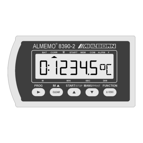
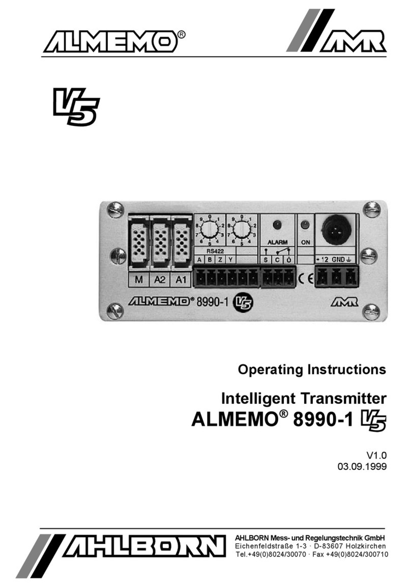
Ahlborn ALMEMO 8390-1 User manual

Operating instruction
Universal transmitter
ALMEMO®8390-1
V1.0
19.11.2003

Universal transmitter 8390-1
Operating instructions
Universal transmitter
ALMEMO®8390-1
With supplementary reference to the ALMEMO®Manual
Table of contents
1. INTRODUCTION........................................................................................3
1.1 Functions ............................................................................................3
1.2 Operating controls................................................................................7
2. PUTTING INTO SERVICE..........................................................................8
3. POWER SUPPLY ......................................................................................9
3.1 Power supply via the mains adapter ....................................................9
3.2 DC voltage supply (option U) ...............................................................9
3.3 Sensor supply .....................................................................................9
3.4 Data saving, reinitialization .................................................................9
4. CONNECTING THE TRANSDUCERS .....................................................10
4.1 Transducers ......................................................................................10
4.2 Measuring inputs and additional channels ..........................................10
5. SENSOR PROGRAMMING .....................................................................12
5.1 Measuring ranges ..............................................................................12
6. MEASURING OPERATIONS ...................................................................14
6.1 Digital interfaces ...............................................................................14
6.2 Cyclic output of measured data for a device ......................................15
6.3 Networking the devices .....................................................................15
6.4 Cyclic output of measured data for networked devices ......................16
7. ANALOG OUTPUT ..................................................................................16
8. TROUBLE-SHOOTING ............................................................................17
9. ELECTROMAGNETIC COMPATIBILITY ..................................................18
APPENDICES..............................................................................................19
Technical data ........................................................................................19
Product overview.....................................................................................20
page 2

Universal transmitter 8390-1
1. INTRODUCTION
The universal transmitter ALMEMO®8390-1 is a new member in our family of
unique measuring devices
- all equipped with Ahlborn GmbH’s patented ALMEMO®connector system.
The intelligent ALMEMO®connector offers decisive advantages when con-
necting sensors and peripherals because all parameters are stored in an EE-
PROM on the connector itself; repeat programming is thus no longer necessa-
ry.
All sensors and output modules can be connected to all ALMEMO®measuring
instruments - all in the same way. Programming and functioning are largely
identical for all units. The following points apply to all devices in the ALME-
MO®measuring system and are described in detail in the ALMEMO®Manual
supplied with each device.
•Detailed description of the ALMEMO®system (Manual, Chapter 1)
•Overview of the device functions and measuring ranges
(Manual, Chapter 2)
•Basic principles, operating instructions, and technical data for all sensors
(Manual, Chapter 3)
•Options for connecting your own existing sensors (Manual, Chapter 4)
•All analog and digital output modules (Manual, Section 5.1)
•Interface modules RS-232, optic fiber, Centronics (Manual, Section 5.2)
•The entire ALMEMO®networking system (Manual, Section 5.3)
•All functions and their operation via the interface (Manual, Chapter 6)
•Complete list of interface commands with all the printouts
(Manual, Chapter 7)
The operating instructions you are now reading cover only those features and
controls that are specific to this device. They often refer to a more detailed
explanation in the Manual (Manual, Section x.x.x).
1.1 Functions
Universal transmitter ALMEMO®8390-1 has one measurement input for all
ALMEMO®sensors. The measuring possibilities are virtually unlimited; there
are 4 channels in the sensor connectors - with over 70 measuring ranges.
ALMEMO®output modules, analog output, or a digital interface can be con-
nected to the output socket. Several devices can be networked via ALMEMO®
network distributors. Sensors can be programmed and measuring instruments
can be configured for data output as and when necessary via the interface and
this is best performed using the accompanying AMR-Control software packa-
ge. A wall mounting is included in delivery. Available options include one or
two integrated analog outputs, an RS-485 interface, or even an Ethernet con-
nector.
page 3

Universal transmitter 8390-1
SENSOR PROGRAMMING
The measuring channels are automatically and completely programmed by the
ALMEMO®sensor connectors. Programming can, however, be modified or
supplemented, as and when necessary, via the interface.
Measuring ranges
Appropriate measuring ranges are available for all sensors with a non-linear
characteristic, e.g. 10 thermocouple types, Ntc and Pt100 sensors, infrared
sensors, and flow sensors (rotating vanes, thermoanemometers, Pitot tubes).
For humidity sensors additional function channels are available for calculating
humidity variables such as dew point, mixture ratio, vapor pressure, and ent-
halpy. Even complex chemical sensors are supported. Measured values from
other sensors can also be acquired using the voltage, current, and resistance
ranges with individual scaling in the connector. Existing sensors can also be
used - so long as the appropriate ALMEMO®connector is connected via its
screw terminals. For digital input signals and frequencies, adapters are availa-
ble with an integrated microcontroller. It is thus possible to connect virtually
any sensor to any ALMEMO®measuring instrument and to change sensors wit-
hout the need for any extra settings.
Function channels
Maximum values, minimum values, and differential values at certain measu-
ring points can be programmed as function channels and further processed
and printed just like normal measuring points.
Units
The two-character units can be modified per measuring channel; the display
thus always indicates the physically correct units. Conversion between °C and
°F is performed automatically.
Measured value designation
Each sensor is identified by means of a 10-character alphanumeric name.
This name, entered via the interface, will subsequently appear in the printout
or, if evaluated by computer, on the screen.
Correction of measured values
The measured value on each measuring channel can be corrected both in
terms of zero-point and gain; this means that even sensors usually requiring
initial adjustment (expansion, force, pH) can be freely interchanged. Zero-
point correction and, partly at least, gain adjustment can be performed at the
touch of a button.
Scaling
The corrected measured value on each measuring channel can also be further
scaled in terms of zero-point and gain - using the base value and factor. The
decimal point position can be set by means of the exponent function.
Limit values and alarm
Per measuring channel two limit values can be set (1 maximum and 1 mini-
mum). In the event of one of these limit values being exceeded, this is indica-
ted in the digital output.
page 4

Universal transmitter 8390-1
Sensor locking
All sensor data stored in the connector EEPROM can be protected by means
of a graduated locking function against undesired access.
MEASUREMENT
For each transducer up to four measuring channels are available; i.e. it is also
possible to evaluate double sensors, individually scaled sensors, and sensors
with function channels. All programmed measuring points are scanned conti-
nuously at a conversion rate of maximum 10 measuring operations per se-
cond; the measured value is calculated, saved, and output, if available, to an
analog output.
Measured value
The measured value for the selected measuring point is scanned continuously
with auto zero and, as and when necessary, with measured value correction.
With most sensors, sensor breakage is detected automatically (except for con-
nectors with shunt, dividers, or additional electronics).
Measuring functions
With some sensors, in order to achieve optimal measured value acquisition,
certain special measuring functions are required. Cold junction compensation
is available for thermocouples; temperature compensation is available for dy-
namic pressure, pH, and conductivity probes. On infrared sensors the parame-
ters for zero-point correction and gain correction are used as the background
temperature and the emissivity factor.
Analog output and scaling
The displayed measured value can, by means of analog start and analog end,
be scaled in such a way that the measuring range thus defined covers the full
analog output range (2 V, 10 V, or 20 mA).
Maximum and minimum values
For each measuring operation the maximum value and minimum value are
acquired and saved to memory. These values can be scanned and, as and
when necessary, deleted.
Differential measurement
It is possible, by setting the measured value to zero, to perform pseudo diffe-
rential measurements with respect to a reference value; with two sensors and
the same measured variables genuine differential measuring operations can
be performed.
PROCESS FLOW PROGRAMMING
To digitally record the measured values of all connected sensors a cyclic mea-
suring point scan using data acquisition software or an internal time-based pro-
cess flow control is required. For this purpose a software clock and the print
page 5

Universal transmitter 8390-1
cycle are available. The measuring operation can be started and stopped via
the interface.
Date and time-of-day
When the measuring instrument is switched on, the date and time-of-day are
set to 01.01.00 00:00:00. For the purposes of logging a measuring operation
these must be reset each time.
Print cycle
Cyclic output of measured values to the interface can be programmed to any-
thing between 1 second and 24 hours.
Print cycle factor
To avoid excessive data flow the data output of certain channels can, as and
when necessary, by means of the print cycle factor, be restricted or altogether
disabled. It is also possible to summate pulses over longer cycles.
Averaging over measuring point scans
The measured values obtained by scanning measuring points can be averaged
either over a number of measuring points or over one particular measuring
point either for the total measuring time or over the print cycle time. Function
channels are provided for the cyclic output of such average values.
Output
All measured values and programming values are accessible via various inter-
face cables with RS-232, RS-422, optic fiber, or Ethernet interface. Measured
data can be output in list, column, or table format. Files in table format can be
processed directly using any standard spreadsheet software. The print header
can be programmed specifically to the company or application.
An integrated Ethernet connector is available as an option - for direct incorpo-
ration in a PC network.
Networking
The transmitter is addressable and can be networked - even over long dis-
tances - via ALMEMO®network distributors.
Software
Each ALMEMO®Manual is accompanied by the AMR-Control software packa-
ge, which can be used to configure the measuring instrument and to program
the sensors. It is also possible using the integrated terminal to perform measu-
ring operations online and to save the measured values to PC. The WIND-
OWS®software package, WIN-Control, can be used for data acquisition with
graphical presentation and complex data processing.
page 6

Universal transmitter 8390-1
1.2 Operating controls
Front :
(1) ALMEMO®-measuring input M0
M0 for all ALMEMO®sensors
M1 to M3 Additional channels
(2) Socket for clamp connectors
6 7 1. Analog output A-, A+
0 to 10 V, option R2/R22
0/4 to 20 mA, option R3/R32
4 5 2. Analog output A-, A+
0 to 10 V, option R22
0/4 to 20 mA, option R32
Rear
(3) Address code switch
Device address 00 to 99
(4) Check lamp
ON Supply, flashes on data trans-
mission
(5) Socket for clamp connectors
+ - Power supply via mains adapter
(ZB1012-NA1, 12V / 0.2A)
RS-485 interface (OA 8390-I)
0 1 input RX+, RX-
2 3 output TX+, TX-
(6) ALMEMO®output socket A1
Analog output (ZA 1601-RK)
V24 interface (ZA 1909-DK5/DKL)
(7) Ethernet option :
Output socket A1
Ethernet output RJ-45 (OA 8390-E)
page 7

Universal transmitter 8390-1
2. PUTTING INTO SERVICE
1. Connect transducer to socket M0 (1); (see Section 4).
2. Ensure the power supply is connected via the mains adapter;
(see Sections 3.1, 3.2).
3. Connect analog output to socket A1 (6) using recording cable ZA 1601-RK.
or option R2/3 to socket 2 pins 6 and 7 (see Manual, Section 5.1.1)
4. Programming or data output via interface
Connect computer via interface cable to socket A1 (6) (see Man., Section 5.2).
Activate supplied software AMR-Control.
Via ‘Setup interface’ set the COM port and transmission rate to 9600 bauds.
Program the sensors via ‘Program measuring point list’.
Measured value display and sensor adjustment via ‘Measuring points -
Measured values’
Data logging in the computer :
- program the print cycle via ‘Devices - Programming’;
- open the terminal window via 'File - Terminal';
- open the file via ‘File - Open’ and enter file name;
- start the measuring operation by means of command button ‘Start’;
- stop the measuring operation by means of command button ‘Stop’;
- close the file via ‘File - Close’.
For the available options and the appropriate pin assignment please see
the rating plate located on the bottom of the device !
page 8

Universal transmitter 8390-1
3. POWER SUPPLY
As power supply there are the following possibilities :
•mains adapter 12 V / 200 mA ZB 1012-NA1
•DC voltage supply, 7 to 13 V DC
•DC voltage supply, 9 to 30 V DC, electrically isolated OA 8390-U
3.1 Power supply via the mains adapter
On the rear of the device there is the socket (5) for connecting an external power sup-
ply. Here by default mains adapter ZB 1012-NA1 (12 V / 200 mA) is connected to the
+ and - terminals by means of the clamp connector. Or, alternatively, you can use
some other DC power source (7 to 13 V).
If, however, the power supply has to be electrically isolated from the transducers,
then option U is required.
3.2 DC voltage supply (option U)
Option U (OA 8390-U) provides an electrically isolated DC voltage supply with a wide
input voltage range, 9 to 30 V. The voltage must also be connected to the clamp /
screw terminal of socket (5) on the device using the clamp connector. It will then be
possible to use the measuring instrument in a 12-volt or 24-volt on-board supply sys-
tem.
3.3 Sensor supply
Whatever the power supply, a sensor supply voltage of approx. 12 V DC (maximum 70
mA) is available on the + and - terminals of the ALMEMO®connector. With special
connectors, 15 V or 24 V DC or reference voltages of 5 V and 2.5 V are also available.
3.4 Data saving, reinitialization
Sensor programming is saved in the connector itself; calibration and process flow con-
trol data is saved in an EEPROM in the device; in the event of an interruption to the
power supply this data is retained intact; only the date and time-of-day are lost and as
and when power is restored these are reset (to 01.01.00 00:00:00).
If you wish to reset the device parameters to their default values, in particular the baud
rate to 9600 bauds, then, when switching on, set the code switches for the address
just once to 99. The address must then of course be reset again.
page 9

Universal transmitter 8390-1
4. CONNECTING THE TRANSDUCERS
Virtually any ALMEMO®sensor can be connected to the ALMEMO®input socket M0
(1). To connect your own existing sensors you simply need the appropriate ALMEMO®
connector.
4.1 Transducers
The ALMEMO®Manual includes detailed descriptions of the comprehensive ALME-
MO®sensor range (see Manual, Chapter 3) and of how to connect your own existing
sensors to ALMEMO®instruments (see Manual, Chapter 4). All standard sensors with
an ALMEMO®connector usually have the measuring range and units already program-
med and can thus be connected to any input socket without further adjustment. A me-
chanical coding system ensures that sensors and output modules can only be con-
nected to the correct sockets. Each ALMEMO®connector also incorporates two snap-
lock levers; these snap into position as soon as the connector is inserted into the so-
cket, thus preventing unintended disconnection if the cable is accidentally pulled. To
withdraw the connector, both these levers must be pressed in at the sides.
4.2 Measuring inputs and additional channels
Measuring instrument ALMEMO®8390-1 incorporates an input socket M0 (1), to which
initially measuring channel M0 is assigned. ALMEMO®sensors can, however, if ne-
cessary, provide four channels. Additional channels are available primarily for
humidity sensors (temperature / humidity / dew point / mixture ratio) or
flow probes and chemical probes incorporating a temperature sensor. A single sensor
can be programmed, if necessary, with several ranges or scaling processes; similarly,
if pin assignment permits, two sensors can be combined on one connector (e.g. rH /
Ntc, mV / V, mA / V, etc.).
Measuring point numbering
Each additional measuring channel in a connector lies one level higher. In this new se-
ries the levels are now numbered in standard decimal form, i.e. the front digit indicates
the level. In this way the measuring point number (and thus also the programmed re-
ference channels) for all devices with 1, 2, 5, or 10 inputs always remains the same. If
reference channels are programmed that are not available in the device, the default re-
ference channel (the 1st in the connector) is used.
On the measuring instrument this gives the following channel assignment :
page 10

Universal transmitter 8390-1
Sensors combined within one connector and sensors with their own
power supply are electrically interconnected and must therefore be opera-
ted in isolation. The voltage applied to the measuring inputs themselves
must not exceed ±5 volts (between B, C, D, A and - ).
The cold junction compensation for thermocouple measurement is integrated in the
device in socket M0.
page 11
channel 4 30
channel 3 20
channel 2 10
channel 1 0
M0
sensors
8390-1

Universal transmitter 8390-1
5. SENSOR PROGRAMMING
Since on ALMEMO®devices all sensor programming is stored in the ALMEMO®con-
nector,
you can connect any ALMEMO®sensor without needing to reprogram. To connect cer-
tain sensors you can even order ALMEMO®connectors that have already been appro-
priately programmed. If, however, you wish to create or scale your own sensors or if
sensor errors have to be continually corrected, you can do the programming via the
serial interface using the AMR-Control software; (see Manual, Section 6.3).
5.1 Measuring ranges
In the measuring point programming the measuring ranges are shown by abbreviati-
ons as listed in the following table :
Transducer Sensor/con-
nector
Measuring range Units Abbrev.
Pt100-1 (ITS90) FP Axxx -200.0... +850.0 °C P104
Pt100-2 (ITS90) FP Axxx -200.00...+300.00 °C P204
Ni100 ZA 9030-FS3 -60.0... +240.0 °C N104
NiCr-Ni (K) (ITS90) FT Axxx -200.0...+1370.0 °C NiCr
NiCroSil-NiSil (N) (ITS90) ZA 9020-FSN -200.0...+1300.0 °C NiSi
Fe-CuNi (L) ZA 9000-FSL -200.0... +900.0 °C FeCo
Fe-CuNi (J) (ITS90) ZA 9000-FSJ -200.0...+1000.0 °C IrCo
Cu-CuNi (U) ZA 9000-FSU -200.0... +600.0 °C CuCo
Cu-CuNi (T) (ITS90) ZA 9000-FST -200.0... +400.0 °C CoCo
PtRh10-Pt (S) ITS90) FS Axxx 0.0...+1760.0 °C Pt10
PtRh13-Pt (R) (ITS90) ZA 9000-FSR 0.0...+1760.0 °C Pt13
PtRh30-PtRh6 (B) (ITS90) ZA 9000-FSB +400.0...+1800.0 °C EL18
Au-FeCr ZA 9000-FSA -270.0... +60.0 °C AuFe
Ntc type N FN Axxx -30.00...+125.00 °C Ntc
Millivolt ZA 9000-FS0 -10.000...+55.000 mV mV
Millivolt 1 ZA 9000-FS1 -26.000...+26.000 mV mV 1
Millivolt 2 ZA 9000-FS2 -260.0...+260.0 mV mV 2
Volts ZA 9000-FS3 -2.0000...+2.6000 V Volt
Difference - millivolt ZA 9050-FS0 -10.000...+55.000 mV D 55
Difference - millivolt 1 ZA 9050-FS1 -26.000...+26.000 mV D 26
Difference - millivolt 2 ZA 9050-FS2 -260.0...+260.0 mV D260
Difference - volt ZA 9050-FS3 -2.0000...+2.6000 V D2.6
Sensor voltage any 0.00...20.00 V Batt
Milliampere ZA 9601FS1 -26.000...+26.000 mA I032
Percent (4 to 20 mA) ZA 9601-FS2 0.00... 100.00 % P420
Ohms ZA 9003-FS 0.0... 500.0 Ohm
Frequency ZA 9909-AK1 0... 32000 Hz Freq
Pulses ZA 9909-AK2 0... 65000 Puls
Digital input ZA 9000-EK2 0.0... 100.0 % Inp
page 12

Universal transmitter 8390-1
Digital interface ZA 9919-AKxx -65000... +65000 DIGI
Infrared 1 FI A628-1/5 0.0... +200.0 °C Ir 1
Infrared 4 FI A628-4 -30.0... +100.0 °C Ir 4
Infrared 6 FI A628-6 0.0... +500.0 °C Ir 6
Snap-on head, normal 20 FV A915-S120 0.30... 20.00 ms S120
Snap-on head, normal 40 FV A915-S140 0.40... 40.00 ms S140
Snap-on head, micro 20 FV A915-S220 0.50... 20.00 ms S220
Snap-on head, micro 40 FV A915-S240 0.60... 40.00 ms S240
Macro FV A915-MA1 0.10... 20.00 ms L420
Water micro FV A915-WM1 0.00... 5.00 ms L605
Dynamic pressure, 40 m/s with TC and PC FD A612-M1 0.50... 40.00 ms L840
Dynamic pressure, 90 m/s with TC and PC FD A612-M6 1.00... 90.00 ms L890
Relative air humidity, capacitive FH A646 0.0... 100.0 %H % rH
Relative air humidity, capacitive, with TC FH A646-R 0.0... 100.0 %H H rH
Mixture ratio, capacitive, with PC FH A646 0.0 ... 500.0 gk H AH
Dew-point temperature, capacitive FH A646 -25.0... 100.0 °C H DT
Partial vapor pressure, capacitive FH A646 0.0 ...1050.0 mb H VP
Enthalpy, capacitive FH A646 0.0 ... 400.0 kJ H En
Humid temperature FN A846 -30.00 ... +125.00 °C P HT
Relative humidity, psychrometric, with PC FN A846 0.0 ... 100.0 %H P RH
Mixture ratio, psychrometric, with PC FN A846 0.0 ... 500.0 gk P AH
Dew point, psychrometric, with PC FN A846 -25.0 ... +100.0 °C P DT
Partial vapor pressure, psychrom., with PC FN A846 0.0 ...1050.0 mb P UP
Enthalpy, psychrometric, with PC FN A846 0.0 ... 400.0 kJ P En
Conductivity probe, with TC FY A641-LF 0.0 ... 20.000 mS LF
CO2sensor FY A600-CO2 0.0 ... 2.500 % CO2
O2saturation, with TC and PC FY A640-O2 0 ... 260 % O2-S
O2concentration, with TC FY A640-O2 0 ... 40.0 mg O2-C
Function channels
Differential channels Mb1 - Mb2 any Diff
Maximum value of channel Mb1 any Max
Minimum value of channel Mb1 any Min
Average value M(t) over time of Mb1 any M(t)
Average value M(n) of Mb2 to Mb1 any M(n)
Sum S(n) of Mb2 to Mb1 any S(n)
Total pulses S(t) of Mb1 ZA 9909-AK2 0... 65000 S(t)
Pulses / print cycle of Mb1 ZA 9909-AK2 0... 65000 S(P)
Alarm value of channel Mb1 any Alrm
Wet bulb globe temperature ZA 9000-FS °C WBGT
Measured value of Mb1 any Mess
Cold junction temperature any °C CJ
Number of averaged values of Mb1 any n(t)
Volume flow m3/h M(t) (Mb1) *Q any mh Flow
TC = Temperature compensation PC = Pressure compensation
page 13

Universal transmitter 8390-1
6. MEASURING OPERATIONS
With measuring instrument ALMEMO®8390-1 up to 4 measuring channels, if
these have been programmed, are scanned continuously at a conversion rate
of 2.5 or 10 measuring operations per second; this ensures continuous humidi-
ty variable calculation or temperature compensation for dynamic pressure pro-
bes and chemical probes; (see Manual, Section 6.5.1.3).
Measured values can be output using any of the following methods :
1. Measured value output to an analog output (see Manual, Section 5.1.1)
2. Once-only measured value output via the interface (s. Man., Sec. 6.5.1.1)
3. Cyclic measured value output via the interface (s. Man., Section 6.5.1.2)
6.1 Digital interfaces
For communication with the transmitter there is the V24 interface cable ZA
1909-DK5 (available as accessory) (see Manual, Section 5.2.1); this is also
available, to cope with environments subject to particularly heavy disturbance,
in optic fiber technology (ZA 1909-DKL). This cable is plugged into socket A1
(6). The baud rate is by default 9600 baud; the file format is 8 data bits, 1 stop
bit, no parity (settings cannot be changed).
Sensors can be programmed and the transmitter can be completely confi-
gured via the serial interface; this is best performed using the AMR-Control
configuration software or a terminal (PC) (see Manual, Chapter 6).
RS-485 interface (option I)
Option I provides an integrated RS-485 interface; with this option, in order to
connect the first device to a computer, one needs the RS-422 / RS-485 bus
driver ZA 5099-AS (see Manual, Section 5.3.3.1) or the RS-422 output of a
network distributor. The transmit and receive lines must be crossed once-only.
Up to 32 extra devices can then be easily networked using parallel 4-wire cab-
ling - even over long distances (maximum 1 km); (see Manual, Section 5.3.3).
Over shorter distances (maximum 100 meters) it is also possible to lead the
power supply over the bus using 6-wire cabling. The transmitter is - in each
such case - electrically isolated from the bus.
Ethernet interface (option E)
With the Ethernet interface it is possible to connect the transmitter to an Ether-
net - PC network. It is even possible in this way to link up to the Internet. The
device can be connected, via an RJ-45 (10BASE-T) plug connector (7), direct-
ly to a PC, switch, or hub. Additional LEDs are provided for the purposes of
monitoring the Ethernet connection.
Having an Ethernet transmitter integrated in measured value acquisition is the
default setting in the Win-Control WC3 software package; if this is not the
case, this can be retrofitted with option WCO6. With additional software
AMR2ips SW5500-C22, it is also possible to operate a number of Ethernet
transmitters.
page 14

Universal transmitter 8390-1
Setting the IP address
The Ethernet transmitter is delivered with the IP address preset by default to
0.0.0.0. With this default address setting it is possible to connect to a DHCP
server (dynamic host configuration protocol). The DHCP server provides the
Ethernet network distributor with a free IP address, a gateway address, and the
subnet mask.
In networks without DHCP server a permanent IP address must be set manu-
ally in the Ethernet transmitter. The necessary software XPort-Installer and
the instructions for using it are provided on the AMR CD (with effect from ver-
sion V5.0) in the folder Zubehoer\Ethernet\XPort-Installer (or via the Internet
under www.ahlborn.com).
Necessary components :
•PC with operating system WINDOWS 9x / Me / NT 4.0 / 2000 (SP2)
•Microsoft Internet Explorer 5 or higher
•Crosslink cable (for direct connection to PC)
Start the self-extracting installation routine “setup.exe“ and follow the instructi-
ons on the screen. You can via the menu enter the hardware Ethernet address
(see rating plate), the desired IP address, and the subnet mask. You can also,
if required, set the baud rate for the transmitter.
6.2 Cyclic output of measured data for a device
If only one transmitter is being used, this can output the measured data via the
interface - automatically, independently, with its own time control, by means of
the print cycle (see Manual, Section 6.5). You can, using a terminal program
on the PC (AMR-Control or WINDOWS Terminal), write the measured values
online to a file and then later evaluate this data using a spreadsheet program;
(see Manual, Section 6.1).
6.3 Networking the devices
ALMEMO®8390-1 transmitters, like all ALMEMO®devices, can also be net-
worked. Since by default only socket A1 (6) is available, networking is only
possible via network distributors (see Manual, Section 5.3.3). If network distri-
butor ZA 5099-NVB is being used, even the power supply can be provided
over the network (see Manual, Section 5.3.3.4). To communicate with networ-
ked devices it is absolutely indispensable that each device should have its own
dedicated address; this is because only one device should respond per com-
mand. Before starting network operation therefore ensure that all the measu-
ring instruments involved are assigned different device numbers. On the AL-
MEMO®8390-1 two code switches (3) are provided for this purpose on the rear
of the device.
Example : Module address 01
page 15

Universal transmitter 8390-1
In network operation consecutive numbers between 01 and 99 should be used;
this ensures that device 00 is not addressed unnecessarily in the event of in-
terruption to the power supply. Before each attempt to communicate with a
device the desired address must be output (see Manual, Section 6.2.1). The
various devices can be addressed manually by a terminal, by a computer, or
by AMR measured data acquisition software.
6.4 Cyclic output of measured data for networked devices
To perform measuring point scanning automatically on a number of networked
modules you will need some form of measured data acquisition software which
will also address the individual modules. This task is usually performed by
Win-Control (WINDOWS 3.xx, 95, 98, and NT) available in a range of versi-
ons. Win-Control provides an online display of this data as line chart, bar
chart, or table and saves it to memory. This data can also be retrieved again
offline, evaluated, and printed out.
7. ANALOG OUTPUT
For the analog registration of the selected measuring point you can, to socket
A1, connect either an analog output cable ZA 1601-RK (see Manual, Section
5.1.1) without electrical isolation or a relay trigger analog adapter ZA 8000-
RTA (see Manual, Section 5.1.3) with electrically isolated analog output. If the
device incorporates integrated analog outputs (option Rxx), the analog signals
are present at terminals 6, 7 of the socket (4) in the case of a single output -
and at terminals 4, 5 and 6, 7 in the case of dual output for double sensors.
It is possible, by means of functions analog output - start and analog output
end, to spread any partial measuring range over the standard output signal in
the three possible variants 0-2 V, 0-10 V, 0 / 4-20 mA (e.g. 0-20 mA for -10.0
to +50.0 °C); (see Manual, Section 6.10.7).
page 16

Universal transmitter 8390-1
8. TROUBLE-SHOOTING
ALMEMO®8390-1 transmitter can be configured and programmed in many
versatile ways. It is suitable for connecting a wide variety of very different
sensors, additional measuring instruments, and peripheral equipment. Given
these numerous possibilities the device may in certain circumstances not be-
have quite as expected. The cause of such unexpected behavior is only very
rarely a device defect; more usually it is incorrect operation by the user, an in-
valid setting, or unsuitable cabling. In such event try to pinpoint and clear the
problem with the aid of the following tests :
Error : Measured values are incorrect.
Remedy: Check the channel’s programming (using the AMR-Control
software); scan the entire programming using the command P15
(s. Manual, Section 6.2.3) and f1 P15 (s. Manual, Section 6.10.1).
Error : Fluctuating measured values, cyclic measuring point scan hangs in
mid-operation.
Remedy: Check the cabling for any inadmissible electrical connections;
unplug any suspicious sensors, replace with hand-held sensors in air
or phantoms (for thermocouples short-circuit A-B, for Pt100 sensors
use 100-Ωresistor) and check, connect sensors again one at a time
and check successively; If a fault persists for any one connection,
then check all wiring, if necessary, insulate the sensor, and eliminate
interference by using shielded or twisted wiring.
Error : Data transmission via the interface does not function.
Remedy: Check the power supply, switch off and then on again !
Check interface module, connections, and settings :
Are both devices set to the same baud rate and transmission mode (see Ma-
nual, Section 6.10.12) ?
Is the correct COM interface on the computer being addressed ?
Are the handshake lines DTR and DSR active ?
To check the data flow and the handshake lines a small inter-
face tester with LEDs comes in very handy; (in ready-to-operate
status the data lines TXD, RXD carry negative potential of ap-
prox. -9V and the LEDs light up green, whereas the handshake
lines DSR, DTR, RTS, CTS carry approx. +9V positive voltage
and the LEDs light up red. For the duration of data transmissi-
on the data line LEDs must flash red).
Test data transmission by means of a terminal (AMR-Control, WIN-Control,
DATA-Control, WINDOWS-Terminal) :
Check the module address and code switch position (see Section 6.3), Ad-
dress the module using its assigned device number Gxy (see Manu-
page 17

Universal transmitter 8390-1
al, Section 6.2.1). Check the programming by means of P15 (see
Manual, Section 6.2.3).
Error : Data transmission in the network does not function.
Remedy: Check to ensure that all modules are set to different addresses.
Address devices individually via terminal and command Gxy.
Addressed device is OK if at least y CR LF is returned as echo.
If transmission is still not possible, unplug external devices and check all de-
vices individually on the data cable to the computer (see above);
check the wiring for short-circuit or crossed wires; Are all network
distributors supplied with power ? Network the devices again one at
a time and check successively (see above).
If, after performing the above-listed checks and remedial steps, the device still
fails to behave as described in the operating instructions, it must be returned
to our factory in Holzkirchen, accompanied by an explanatory note, error des-
cription, and if available test printouts. With the AMR-Control software you
can save logs in terminal mode and print these out using the editor.
Service address :
Ahlborn Mess- und Regelungstechnik GmbH
Eichenfeldstr 1-3
D-83607 Holzkirchen, Germany
9. ELECTROMAGNETIC COMPATIBILITY
ALMEMO®measuring instrument 8390-1 complies in full with the safety requi-
rements specified in the EU directive on the harmonization of laws in EU
member states relating to electromagnetic compatibility (EMC) (89/336/EEC).
The following standards have been applied in evaluating the product :
EN 61326:1997/A1:1998 IEC 61000-3-2:1995,
IEC 61000-4-2:1995, 8 kV
IEC 61000-4-3:1995, 3 V/m: deviation <50 µV
IEC 61000-4-4:1995, 1 kV
The following advisory notes must be observed when operating the device :
1. If the standard sensor is extended (1.5 meters) care must be taken to ensu-
re that the measuring lines are not laid together with high-voltage power ca-
bles or that they are properly shielded so as to prevent spurious interfe-
rence from being induced in the system.
2. Using the device in strong electromagnetic fields may aggravate measuring
errors (<50 µV at 3 V/m and 1.5 meters thermocouple sensor). After expo-
sure to such irradiation ceases, the device will again operate within its tech-
nical specifications.
page 18

Universal transmitter 8390-1
APPENDICES
Technical data
(see also Manual, Section 2.2)
Measuring inputs : one ALMEMO®socket for all ALMEMO®sensors
Channels : 4 channels / sensor maximum (measuring and
function channels, depending on sensor type)
Sensor power supply : Mains adapter :approx. 12 V, maximum 70 mA
Measuring rate : 2.5 / 10 measuring operations per second
continuous on all channels
System accuracy : ±0.05% of measured value ±2 digits
Temperature drift : 0.01% / K
Cold junction compens.: ± 0.2 K ±0.01 K / °C (-30 to +80 °C)
Outputs : 1 ALMEMO®socket for analog module or interface
Option OA 8390-I RS-485 interface, electrically isolated, integrated
Signals : RX+, RX-, TX+, TX-, line, maximum 1 km
Option OA 8390-E Ethernet interface, electrically isolated , integrated
Socket: RJ-45 10/100 base-T switchover. automatic
Option OA 8390-Rx Analog output R2 : 0 to 10 V, R3: 0/4 to 20 mA,
electrically isolated
Accuracy : ±0.1% ± 6 digits, resolution : 15 bits
Temperature drift : 1 digit / K
Option OA 8390- Rx2 2 analog outputs R22 : 0 to 10 V, R32: 0/4 to 20 mA,
electrically isolated
Accuracy : ±0.1% ± 1 digit, resolution : 12 bits
Temperature drift : ± 0.005 % / K
Equipment
A/D converter : delta-sigma, 16 bit, 2.5 / 10 measuring
operations per second
Microprocessor : NEC 78F0078
Power supply : 7 to 13 V DC, not electrically isolated
Mains adapter : ZB 1012-NA1 230 V AC to 12 V DC / 200 mA
electrically isolated
Current consumption Without input and output modules : approx. 4.5 mA
With Ethernet interface option : approx. 100 mA
With analog output option :
approx. 50 mA + 2.5 x actually analog current
Housing 108 x 60 x 29 mm, ABS (acrylonitrile butadiene styrene)
high impact resistance (maximum 70 °C)
Operating temperature -10 to +60 °C
Storage temperature -30 to +60 °C
Ambient relative humidity : 10 to 90 % (non-condensing)
Delivery includes : Measuring instrument ALMEMO®8390-1
Operating instructions ALMEMO®8390-1
page 19

Universal transmitter 8390-1
ALMEMO®Manual
AMR-Control software on CD
Product overview
Order no.
Universal transmitter ALMEMO®8390-1
1 input, 4 channels, 1 ALMEMO®output for analog output
or interface (network-capable) MA 8390-1
Options :
Option U : DC voltage supply, electrically isolated, 9 to 30 V DC OA 8390-U
Option I: RS-485 interface, electr. isolated (including option U) OA 8390-I
Option E: Ethernet interface (Option U not possible) OA 8390-E
Option R2: Single analog output, 0 to 10 V, 15 bit, electr. isolated OA 8390-R2
Option R3: Single analog output, 0/4 to 20 mA, 15 bit, electr. isol. OA 8390-R3
Option R22: Double analog output, 0 to 10 V, 12 bit, electr. isol. OA 8390-R22
Option R32: Double analog output, 0/4 to 20 mA, 12 bit, electr. isol. OA 8390-R32
Option HS: Fixture for top-hat rail mounting OA 2290-HS
Accessories
Mounting plate with 2 clips ZB 8390-H
Mains adapter 12 V / 200 mA ZB 1012-NA1
ALMEMO®V24 data cable, electrically isolated, 9600 baud
(maximum 115.2 kbaud), 1 mA ZB 1909-DK5
ALMEMO®Analog output cable -1.25 to 2.00 V, 0.1 mV / digit ZA 1601-RK
Measured value acquisition software WIN-Control SW 5500-WCx
Software option for connecting an Ethernet transmitter (not WC3) SW 5500-WC06
Software option AMR2ips for several Ethernet transmitters SW 5500-C22
Your contact :
page 20
Table of contents
Other Ahlborn Transmitter manuals