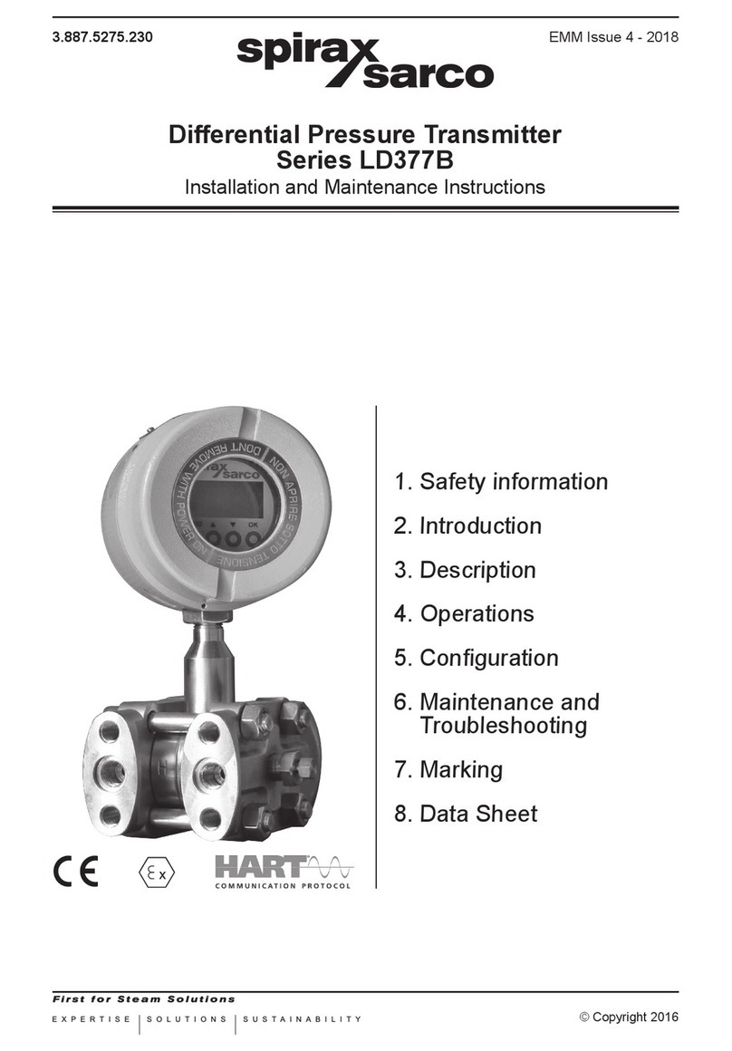
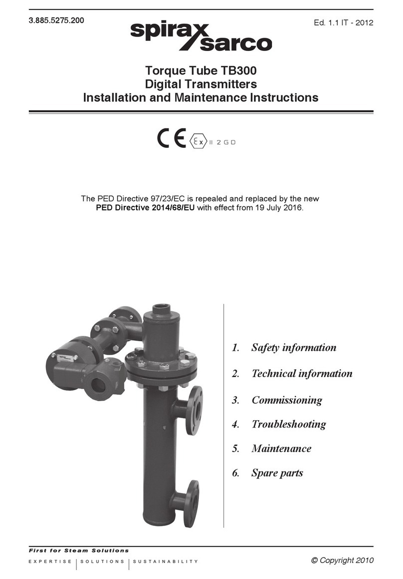
Spirax Sarco LD377BL Series User manual

EXPERTISE SOLUTIONS SUSTAINABILITY
3.887.5275.250 EMM Issue 4 - 2018
© Copyright 2016
Level Transmitter
Series LD377BL
Installation and Maintenance Instructions
1. Safety information
2. Introduction
3. Description
4. Operations
5.Conguration
6. Maintenance and
Troubleshooting
7.Marking
8. Data Sheet

23.887.5275.250

3
3.887.5275.250
1. Safety information
Safeoperationoftheseproductscanonlybeguaranteediftheyareproperlyinstalled,commissioned,
usedandmaintainedbyqualiedpersonnel(seeSection1.11 on this document) in compliance
withtheoperatinginstructions.Generalinstallationandsafetyinstructionsforpipeline andplant
construction,aswellastheproperuseoftoolsandsafetyequipmentmustalsobecompliedwith.
1.1 Intended use
The trasmitters object of the present instructions comply with the directive ATEX 2014/34/UE and
arecharacterizedbythefollowingmotodhdsofprotection:
II1/2GExdIICT6Ga/Gb
TheyaresuitableforinstallationinZone1,Zone2.
For connections and installation refer to this manual.
1.2 Access
Ensuresafeaccessandifnecessaryasafeworkingplatform(suitablyguarded)beforeattempting
toworkontheproduct.Arrangesuitableliftinggearifrequired.
1.3 Lighting
Ensureadequatelighting,particularlywheredetailedorintricateworkisrequired.
1.4 Hazardous liquids or gases in the pipeline
Consider what is in the pipeline or what may have been in the pipeline at some previous time.
Consider:ammablematerials,substanceshazardoustohealth,extremesoftemperature.
1.5 Hazardous environment around the product
Consider:explosion risk areas,lack of oxygen(e.g. tanks, pits),dangerous gases, extremesof
temperature,hotsurfaces,rehazard(e.g.duringwelding),excessivenoise,movingmachinery.
1.6 The system
Considertheeectonthecompletesystemoftheworkproposed.Willanyproposedaction(e.g.
closingisolationvalves,electricalisolation)putanyotherpartofthesystemoranypersonnelatrisk?
Dangersmightincludeisolationofventsorprotectivedevicesortherenderingineectiveofcontrols
oralarms.Ensureisolationvalvesareturnedonandoinagradualwaytoavoidsystemshocks.
1.7 Pressure systems
Ensure that any pressure is isolated and safely vented to atmospheric pressure. Consider double
isolation(doubleblockandbleed)andthelockingorlabellingofclosedvalves.Donotassumethat
thesystemhasdepressurisedevenwhenthepressuregaugeindicateszero.
1.8 Temperature
Allowtimefortemperaturetonormaliseafterisolationtoavoiddangerofburns.
1.9 Tools and consumables
Beforestartingworkensurethatyouhavesuitabletoolsand/orconsumablesavailable.Useonly
genuineSpiraxSarcoreplacementparts.

43.887.5275.250
1.10 Protective clothing
Considerwhetheryouand/orothersinthevicinityrequireanyprotectiveclothingtoprotectagainst
thehazardsof,forexample,chemicals,high/lowtemperature,radiation,noise,fallingobjects,and
dangerstoeyesandface.
1.11 Permits to work
All work must be carried out or be supervised by a suitably competent person. Installation and
operatingpersonnelshouldbetrainedinthecorrectuseoftheproductaccordingtotheInstallation
and Maintenance Instructions.
Whereaformal‘permittowork’systemisinforceitmustbecompliedwith.Wherethereisnosuch
system,itisrecommendedthataresponsiblepersonshouldknowwhatworkisgoingonand,where
necessary,arrangetohaveanassistantwhoseprimaryresponsibilityissafety.
Post‘warningnotices’ifnecessary.
1.12 Electrical work
Beforestartingworkstudythewiringdiagramandwiringinstructionsandnoteanyspecialrequirements.
Considerparticulary:mainssupplyvoltageandphase,local mains isolation, fuse requirements,
earthing,specialcables,cableentries/cableglands,electricalscreening.
1.13 Commissioning
Afterinstallationormaintenanceensurethatthesystemisfullyfuctioning.
Carry out test on many alarms or protective devices
1.14 Disposal
Unwanted equipment should be disposed of in a safe manner.
1.15 Returning products
CustomersandstockistsareremindedthatunderECHealth,SafetyandEnvironmentLaw,when
returningproductstoSpiraxSarcotheymustprovideinformationonanyhazardsandtheprecautions
tobetakenduetocontaminationresiduesormechanicaldamagewhichmaypresentahealth,safety
orenvironmentalrisk.ThisinformationmustbeprovidedinwritingincludingHealthandSafetydata
sheetsrelatingtoanysubstancesidentiedashazardousorpotentiallyhazardous.
Warning!
Exclusivelyfollowtheinstructionsindicatedinthisdocument.Failuretocomply
withthisdocumentmaycauseinjurytohealthormaydamagetheequipment.
SPIRAX SARCO®donottakesanykindofresponsibilityfordamagesduetofailure
to comply with this document.

5
3.887.5275.250
2. Introduction
2.1 Product Overview
TheSpiraxSarcoLDSerieselectronictransmittersaredevicesthatuseasensortomeasurepressure,
levelandtemperature,andtransmitacurrentsignal(4÷20mA)proportionaltothemeasuredvariable.
TheLDSeriesconsistsofthefollowingmodels:
TT352 Electronic temperature transmitter
LD256 Electronic pressure transmitter
LD357B Electronicdierentialpressuretransmitter
LD357BL Electronic level transmitter
Mandatory!
Theaccessoriesusedforthecableentriesandtocloseunusedshallbecerticated
accordingtothestandardsEN60079-0andEN60079-1forthegasgroupsIICor
IIB,accordingtothetypeofprotectionimplemented.
2.2 Attention!
ThismanualdoesnotcontaininformationconcerningalltypeofTransmitteroralldierentinstallation
and/orworkingandmountingsolutions.
Formoreinformationorforparticularproblemsnotconsideredinthismanual,pleaseaddressto
ourtechnicaloce.
Thewarrantyperiodistheonecontemplatedinourgeneralservicingconditions.
This warranty is neither increased nor restricted by the contents of this manual.
ThisTransmitterhastobeinstalledandusedonlybyqualiedpersonswhohaverstcheckedthe
correctnessofsupplyvoltagesothatbothinstandardworkingconditionsandinpresenceofdamages
oftheplantorofanypartofit,nodangerousvoltagecanreachtheTransmitter.
AstheTransmittercanbeutilizedbothwithhighpressurevaluesandwithaggressivemediaitmust
beconsideredthatanincorrectuseofitcouldbringevenseriousdamagestopeopleandthings.
Acorrectandsafeworkingneedsanadequatetransport,stockandmountingotherthananappropriate
maintenance service.
SoitisnecessaryforthepeoplehandlingtheseTransmittertohaveknowledgeandexperiencein
mounting,servicingandworkingandtohavetitletodotheirjobwithreferenceto“SafetyStandards“.

63.887.5275.250
2.3 DenitionsandSymbols
Inthismanualareusedthefollowingsymbolsandlabels:
Equipmentforuseinpotentiallyexplosiveatmospheres
II 1/2G
EquipmentGroupIICategory1/2G,suitableforpotentiallyexplosivearea(gases,
vapoursormists)tobeinstalledinaseparationwallbetweenZone0(process
side)andZone1(externalside)
Ex d DevicewithExplosionProofEnclosure
IIC GroupIICapparatus,tforsubstancesofgroupIIC,IIBandIIA(onlywhenused
intheambienttemperaturerange-40°Cto60°C)
IIB GroupIIB apparatus, t for substancesofgroupIIBandIIA(when used inthe
ambienttemperaturerange-40°Cto80°C)
TemperatureClassofthetransmitter(maximumsurfacetemperature)
T6, onlywhenusedintheambienttemperaturerange-40°C÷60°C
T5, onlywhenusedintheambienttemperaturerange-40°C÷80°C
Ga/Gb EquipmenttobeinstalledintheboundarywallbetweenanarearequiringEPLGa
and the less hazardous area
Warning!
Warning label, used to warn about hazardous materials, locations, or objects,
includingelectriccurrents,poisons,andotherthings.
Prohibition!
Prohibitionlabel,usedtoindicatesomethingisnotpermitted.
Mandatory!
Mandatorylabel,usedtosetobligationtaskstobeperformedbytheuser.
Information!
Informationlabel,usedtosetgeneralinformationfortheuserorwarnabouthazards
for the equipment.

7
3.887.5275.250
3. Description
The LD377BL series SMART dierential pressure transmitters are microprocessor based
instrumentsthatcombinetheanalogsignaladvantages(4-20mA)togetherwiththeexibilityof
digitalcommunicationusingHART®protocol.They can be remotely congured byauniversal
handheldterminal(HHT)orbyaPCwithadedicatedinterface.
Moreover,itispossibletolocallyconguretheinstruments(zeroandspan)bymeansofpush
buttonsandtodisplaythedataonthewideLCDdisplay.
ThetransmitterseriesLD377BL,measuredierentialpressurewithspansfrom1.2to20000mbar
withastaticpressureupto200bar.Thepressuremeasuringelementisapiezoresitivesensor.It
is possible to choose a variety of sensors to satisfy all process conditions.
TheSpiraxSarcomeasuringcellcontainsthesensorandtransmitsthepressuretotheelectronics.
ThermaldriftiscompensatedusingthetemperaturesignalgeneratedbyaPTCthermistorintegrated
inthesensoritself.Basedonthesereadingsthemicroprocessorgeneratesthe4-20mAanalog
output"twowiressystem"anddisplaysthepressuremeasurementontheLCD.Someofthemain
characteristicsofthismicroprocessor-basedtransmitter,are:
- WideRangeability;
- Automatictemperaturecompensation;
- DigitalcommunicationusingHART®protocol.
Cable gland
Sensitive element
Enclosure
Fig. 1 - Level transmitter LD377BL
Process connection
Nom
Range
(mbar)
Span
min/max
(mbar)
Range Limits
min/max
(mbar)
0/350 23/350 -350/+350
0/1000 67/1000 -1000/+1000
0/2500 167/2500 -2500/+2500
0/5000 333/5000 -5000/+5000

83.887.5275.250
4. Installation
4.1 TransmitterIdentication
Transmitterdatacanbefoundonthenameplatexedonthetopoftransmitterenclosure(seeMarking).
TheSerialNumbermustbequotedattheoccurrenceofaspecicrequesttothemanufacturer.
4.2 General mounting requirements
Priorinstallationshallbeobservedfollowingconsiderations:
- CheckwhetherTransmitter’soperatingconditionsarewithinthelimitsasreportedinthenameplate,
technicalspecicationssheetsand/orlabel.
- Make sure that the operating conditions are compatible with the specication given to the
manufacturer.
Mandatory!
- Formeasurementinthepresenceofparticularlyhotliquids(e.g.steam)make
surethattheTransmitterissuppliedwithasuitablennedarm.
- Forviscousliquidsorthosecontainingsolidparticlesinsuspensionmakesure
thattheconnectiontotheprocessisasuitableoneinordertoavoidclogs.
Warning!
Directsunlightmaycauseseriousdamagestotheinstrument.
NeverinstallstandardTransmitterunderthesunorinanyotherlocationwhich
couldcausedirectoverheatingthroughradiation.
Fig. 2 - Mounting requirements
Zone 0
Direct
Sunlight
Zone 1

9
3.887.5275.250
4.3 Mechanical Installation
TheTransmittershouldbelocated,ifpossible,atsomeeasilyaccessible,welllightedplaceonthe
vessel,inordertoallowputtinginoperationsandmaintenancework.Locationshouldalsobesuch
thatambienttemperatureattheTransmitterenclosurebenotexcessive(seeMARKING).
Information!
- Plantoverpressure/over-temperature:observeratingplate.
- Installationonseismicareas:informtechnicaldepartment.
- Incaseofunstableuids:informtechnicaldepartment.
- Incaseofdamages:informtechnicaldepartment.
- Inspection frequency: consideration should be given to applicable national
legislation.
Warning!
- Theprocessconnectionmustberealizedin suchawaythatguaranteesthe
holdatthemaximumworkingpressureandtemperature.
- Do not overcome the maximum pressure and temperatures indicated in the
technical data sheet of the selected model.
- Whenthedeviceisconnectedtotheprocessitcanbesubmittedtohighpressures
and temperatures. To avoid accidents subsequent to sudden discharge of
pressureand/ortocontactwithdangerousorammableuidsitisnecessary
totakethemaximumattentionwhentheTransmitteristakeno,heatedor
repaired,verifyingthatitisisolatedfromtheprocessandisnotsubmittedto
pressure and/or temperature.

10 3.887.5275.250
4.4 Installation for relative pressure measurement
ThetransmittersLD377BLmaybeusedforrelativepressuremeasurementsorlevelmeasurements
intanksorpiping.InFig. 3thesimplestmounting,directonpiping,isillustrated.
Warning!
- Remembertointroducealwaysasecurityvalveinordertoputinmaintenance
operations when necessary.
- Whentheconnectionsarelocatedonaverticalprocessline,theowshouldbe
upward.
Information!
Fig. 3 e Fig. 4 show some of the installations recommended by ISO 2186 Standards.
RefertothisStandardformoreinformation.
Fig. 3 - Level measurements in open vessels

11
3.887.5275.250
Fig. 4 - Level measurement in closed vessels
Information!
- ReferringtoFig. 4:thedescendingpipescanbelledwithcondensatevapors
oftheprocessuidorwithsuitableinertliquidtopreventdirectcontactwiththe
transmitterdiaphragm.
Mandatory!
- PressureconnectionsonmodelLD377BLaremarkedwith"H"("+")and"L"("-");
thehigherpressurewillbeappliedto"+"side.
- Alwayscheckcarefullyallmanifolds,reducersifany,ventsanddrainplugsfor
leaks.

12 3.887.5275.250
4.5 Electronic head orientation
Inordertorotatetheelectronicheadinthedesiredpositionyoumustfollowthesepassages(Fig. 5):
• unscrewthenut(A)withkeyCH.24;
• byhandgentlyrotatetheenclosure(B)inthedesiredposition;
• oncethedesiredpositionisreachedxthenut(A)againwiththesamekey.
Fig. 5 - Rotating the transmitter head
Information!
Itisnotnecessarytoturnothesupply.

13
3.887.5275.250
Loop4-20mA
For remote indicator
(OPTIONAL)
4.6 Electrical connection
Undertherearcapisplacedtheterminalblockreportingtheelectricpolarity(Fig. 6).
Insert the power supply cable into the enclosure through one of the two threaded openings.
Transmitter is protected from accidental inversion of polarity. For a better use is recommended
atwistedpair cable (22AWGmin).Avoidplacing Transmitternear devicespoweredinACor
Switching.Connectground-tapoftheTransmittertothelocalcommonearth(PE)asindicatedin
paragraphEarthing.
Warning!
Thethreadedopeningthatisnotusedmustbesealedusingasuitablecap.
Thecapsincludedinthedeliveryareonlyforprotectionduringtransport.
Fig. 6 - Electrical connection of the power cable to the terminal block
Information!
Impedance of the cables denes the possible maximum length for digital
communication.It'srecommendedusingcablewithalowimpedance.Themaximum
lengthofthepointtopointconnection,withaloadof250ohmandsingletwisted
cable22AWG-207pF/mit'sabout1000meters.
Themaximumconnectionlengthfortheanalogsignalonlyislimitedbytheloads
(connecteddevicesandcable)presentinthecurrentloop.
Toobtainoutputsignalof4-20mA,youhavetodeterminetheminimumsupplyvoltageasafunction
oftheloadrelation:seeFig. 7.Fromthefollowingformulayoucanachievetherightminimumvalue
ofsupplyvoltage:
Vdc = 0.0215xRL+ 12
Where:RL= output load [Ohm].
The power supply source to assure a minimum current value of 24 mA.
Earthing
Loop
4-20mA

14 3.887.5275.250
Mandatory!
Inordertoobtaina4÷20mA+Hart®output a minimum load of 250 Ohm is required.
TAG -1 2 3 4
Vdc 12.5 17.4 24 25.2 30
Ohm 23 250 558 615 837
Fig. 7 - Operating area for Ex d protection
TheelectronictransmitterstotallycomplywiththeHART®protocolspecicationRevision6.0,sothey
includeremoteprocessvariableinterrogation,parametersettinganddiagnostics.
Thedeviceisa4÷20mA2-wiretransmitter,withFSKcommunication.
ItispossibletoreadviaHART®thefollowingvariables:
PV:transmittermainmeasure;
SV:%ofthespan;
TV:analogoutput;
QV: electronic board temperature.
Please refer to Fig. 8 for the Hart®modemconnectionontransmitter's4÷20mAloop.
In Fig. 9 the multidrop connection type is shown.
Operating area
Vdc

15
3.887.5275.250
Information!
Atmaximum15transmitterscouldbeconnectedinparallelonthesameline.
Attention: when more transmitters are connected on the same line the current
standingontheresistor(250-ohm)isequalto
4mA x N of connected instruments.
Thiscouldcauseahighelectricpotential.Besurepowersupplyissucient.
Fig. 8 - 4÷20 mA + Hart®modem connection
Fig. 9 - Only Hart®Multidrop connection

16 3.887.5275.250
Fig. 10 - DCS connection
Mandatory!
Transmitter response time is <256ms.
DCS POLLING time must be set approximately at 800 ms in order to avoid
updatingproblemsbothinanaloganddigitalmeasurement.
OnrequestthetransmittercanbesuppliedinordertosupportaPollingtimeof
500 ms but with a minimal consumption of 5 mA.
4.7 Explosion Proof Protection
In case of use in areas with danger of explosion, it must be veried that the identied type of
transmittertsfortheclassicationofthezoneandforthepresenceofammablesubstancesin
theplant(seeMarking).
Thesafetyessentialrequisiteagainsttheriskofexplosionintheclassiedareasarexedfromthe
EuropeanDirectives2014/34/EUof26February2014(asfarasitconcernsthe'Equipment')and
1999/92/ECofDecember16th1999(asfarasitconcernsthe'WorkingEnvironment').
Warning!
Fortheelectricalconnectionspleasefollowtheinstructionsbroughtinthisoperator
manualstakingcarethatfortheuseinclassiedareasitisnecessarytoforesee
thestandardEN60079-14.
The accessories for cable entry (which must be threaded ½" NPT) must be
certied following the Standards EN 60079-Series (for Tamb >70°C must be
certiedforT>90°C).
Prohibition!
Donotopenthecoversoranypartofthedeviceindangerousareawhencircuitalive.
Forexplosionproofsafetyinstallation,itismandatorytodisconnecttheelectric
supplybeforeopeningthedevice.

17
3.887.5275.250
4.8 Earthing
Warning!
Theearthconnectionisrequiredtopreventdamagetopeopleandmalfunction
of the instrument.
- Case 1: Installing the instrument in a plant devoid of earthing systems
Inthecasewheretheplantdevoidofearthing,itisnecessarytoconnecttheearthwiretothe
terminalblockthroughthecablethatcarriesthesignalandthepowersupply(Fig. 6).
- Case 2: Installing the instrument in a plant provided with earthing systems
Makesuretheearthing(GND)ofthesystemhastheleastresistancepossible.
Fig. 11 - 4 ÷ 20 mA loop connection with plant provided with earthing systems
Warning!
In the case represented in Fig. 12,withintheearthwiremayalsoscrollthrough
thecurrentprotectionofotherinstrumentswheretheearthingofthesystem(GND)
had not been carried out in an optimal manner.
You can add an additional earth wire with section not less than 4 mm2to ensure such connection.

18 3.887.5275.250
Fig. 12 - Earthing in the housing
Warning!
Thehosemustnotbeconsideredasaprotectionagainstelectricshockforthe
protectionof security,butas protection against electromagnetic interferenceof
theinstrument.Therefore,inthecaseoflongdistancecable(L>20m),bothends
of the braid must be connected to the chassis or to the connectors. In the case
ofcablesL<20meters,willbesucienttoconnectthebraidonlyfromtheside
"Power Supply".
Fig 13 - Earthing of the sock for cables longer than 20 meters

19
3.887.5275.250
5. Operations
5.1 Operations
Eachtransmitter is calibrated infactoryandhasonthe nameplate thecongurationdata.Ifnot
dierentlystatedinthepurchaseorderthetransmitterisconguredasfollow:
Upper Range Value(Higherpressurevalue):refertothedatasheetofunit
Lower Range Value(Lowerpressurevalue):refertothedatasheetofunit
Damping 0 sec.
5.2 Conguration
ThetransmittershowsthestatusandthemeasureonthedotmatrixLCD(Fig. 14).
Thespanisfrom-99999to999999.
Theinputsignaltothetransmittercanberelatedtotheoutputsignalinthefollowingways:
Direct mode =4÷20mAoutput
Reverse mode =20÷4mAoutput
Thedirectmodeisobtainedbysettingthelowerrangepointwiththelowestvalueoftherange(e.g.
0.1bar)andbysettingtheupperrangepointwiththehighestvalue(e.g.0.5bar).
Thereversemodeisobtainedbysettingthelowerrangepointwiththehighestvalueoftherange
(e.g.0.5bar)andbysettingtheupperrangepointwiththelowestvalue(e.g.0.1bar).
Todisplaythetemperaturevaluesofthesensorpushthefollowingkeyduringtransmitteroperation:
= electronic board temperature.
Theunitofmeasure(°C/°K/°F)isdenedintheentryTEMPUNITinthekeyboardmenu(Fig. 14).
Fig. 14 - LD377BL Display
Displayed value
Measuringunit
Choicebargraph/%span
Board temperature display
Menuentering
Bargraph/%Span

20 3.887.5275.250
5.3 KeyboardConguration
The electronic transmitters have some conguration functions available via keyboard and LCD
display,providedwiththetransmittersthemselves.
Pressthe[MENU]buttontoenterthepasswordenteringdialog(thedefaultpasswordis0000).
Conrmby[OK]toenterthecongurationmenu.
Thedisplaywillallowtochoosefromthedierentfunctionsdescribedinthetablebelow.Usethe
and buttonstoshowthesequenceoftheavailablefunctionsandpress[OK]toconrmthe
selected function.
Whenthedisplayisinnumericalenteringmode,thecursorwillblink.
To move the cursor press the ;button;toraisethevalueofthedigitpressthebutton. Press
the[OK]buttontoconrm;useinsteadthe[MENU]buttontocancelthemodicationsandtogo
back to the standard display.
Function Display
name Use Choice span
Zerosetting LRV
Measure linked to the zero
and to the 4mA output. The
measuringunitisshowninthe
lowerrightcornerofthedisplay.
Between the sensor limits
Full span
setting URV
Measure linked to the full span
and to the 20mA output. The
measuringunitisshowninthe
lowerrightcornerofthedisplay.
Between the sensor limits
Measuringunit
selection
PV UNIT
(disabledin
volumetric
owmeters
mode)
Measuring unit selection from
the available ones. Press or
to scroll.
Pressure:
bar,mbar,Pa,hPa,kPa,MPa,
mmH2O,mH2O,cmH2O,Kg/cm2,
mmHg,psi,Torr,inHg,Atm,
FtH2O,g/cm2,inH2O
Flow
m3/h
Temperature
unit selection TEMP UNIT
Indicates the choice of the
unit of measurement of the
temperature.
°C,°K,°F
Transfer
function
XFR FUNC
(disabledin
volumetric
owmeters
mode)
Selecting of current output in
linear or square root mode.
LIN=linear
SQRT=volumetricowmeter
Fault
conguration
ALARM
TYPE
Fault condition analog output
selection.
NONE=noaction
21mA
3.85mA
LAST=lastreadvalue
Damping
setting
DAMP
VALUE
Insertthesignalaveragingtime
constant. 0÷60s
Automatic
zero elevation OFFSET
At the button pushing the
transmitter performs the zero
elevation, in manner to put
to zero the actual measure.
The elevation is applied to the
whole span.
-
Table of contents
Other Spirax Sarco Transmitter manuals
Popular Transmitter manuals by other brands

Upgrading everyday security
Upgrading everyday security EL4601 quick start guide

Nailor
Nailor ELECTRA-FLO G5 Operation and maintenance manual

BFT
BFT PR2 installation manual

SENTRONIC
SENTRONIC M-SYSTEM Mini-MW Series manual

ATX
ATX QFOT1L Installation & operation manual

Knick
Knick VariTrans P 41000 TRMS manual