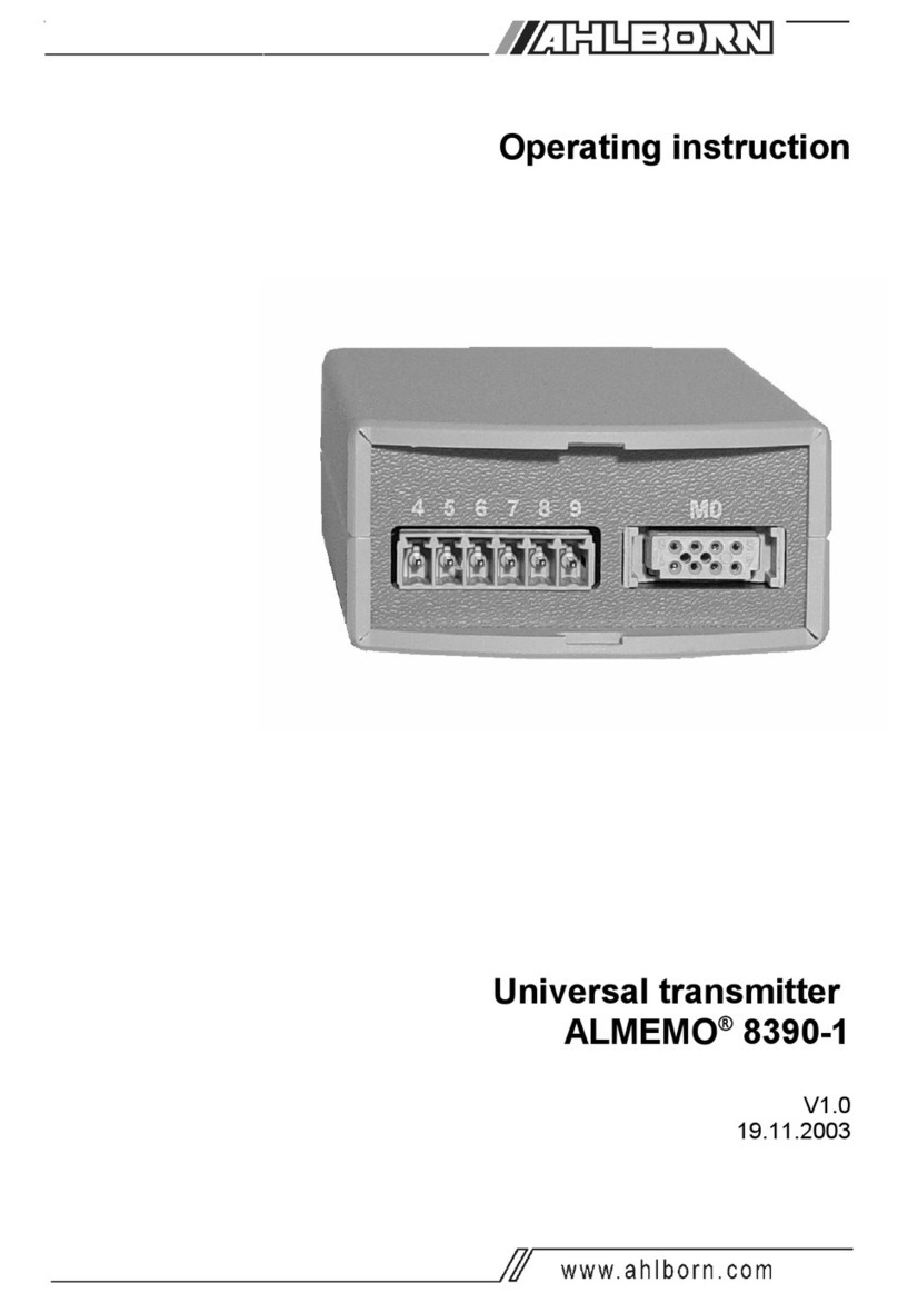
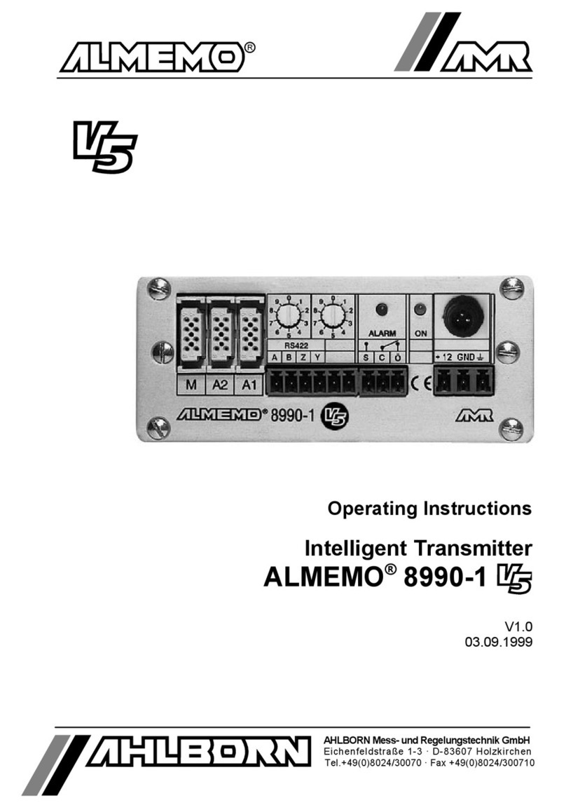
Ahlborn ALMEMO 8390-2 User manual

Operating instruction
Universal transmitter
ALMEMO®8390-2
V1.0
13.11.2003
ALMEMO®8390-2 1

Operating istruction
Universal transmiter
ALMEMO®8390-2
With supplementary reference to the ALMEMO® Manual
Table of contents
page
1. INTRODUCTION 5
1.1 Functions 6
1.2 Operating controls 9
2. PUTTING INTO SERVICE 11
3. POWER SUPPLY 12
3.1 Power supply via the mains adapter 12
3.2 DC voltage supply (option U) 12
3.3 Sensor supply 12
3.4 Data safeguarding, reinitialization 12
4. CONNECTING THE TRANSDUCERS 13
4.1 Transducers 13
4.2 Measuring inputs and additional channels 13
5. DISPLAY AND KEYPAD 14
5.1 Display 14
5.2 Function selection and function activation 17
5.3 Keypad 20
5.4 Data input 21
6. MEASURING OPERATIONS 22
6.1 Measuring point scanning and measuring point display 22
6.1.1 Selecting the measured value and the measuring point 23
6.1.2 Maximum and minimum value memories 23
6.2 Measured value correction and compensation 24
6.2.1 Setting the measured value to zero 24
6.2.2 Sensor adjustment, zero-point, and gain 25
6.2.3 Entering a setpoint 26
6.2.4 Cold junction compensation 27
6.2.5 Atmospheric pressure compensation 27
6.2.6 Temperature compensation 28
6.3 Measuring point scans and data output 29
6.3.1 Once-only measuring point scan 29
2 ALMEMO®8390-2
Table of contents

6.3.2 Cyclic measuring point scan 30
6.3.3 Output formats for measured value lists 30
6.3.4 Manual data output 31
6.4 Averaging 32
6.4.1 Smoothing out measured values by means of a sliding average 32
6.4.2 Averaging mode 33
6.4.3 Averaging over the time from start to stop 34
6.4.4 Averaging over single measurements 35
6.4.5 Volume flow measurement 36
6.4.6 Cyclic averaging 38
7. SENSOR PROGRAMMING 39
7.1 Selecting a measuring point 39
7.2 Locking the sensor programming 39
7.3 Limit values 40
7.4 Correction values 40
7.5 Scaling, decimal point setting 41
7.6 Changing the units 42
7.7 Selecting the measuring range 43
8. ANALOG OUTPUT 46
8.1 Scaling 46
9. DEVICE PROGRAMMING 47
9.1 Date and time-of-day 47
9.2 Baud rate, data format 47
9.3 Device address and networking 48
10. TROUBLE-SHOOTING 49
11. ELECTROMAGNETIC COMPATIBILITY 51
ALMEMO®8390-2 3
Table of contents

1. INTRODUCTION
The universal measuring instrument ALMEMO®8390-2 is a new member in our
family of unique measuring devices - all equipped with Ahlborn GmbH’s paten-
ted ALMEMO®connector system. The intelligent ALMEMO®connector offers
decisive advantages when connecting sensors and peripherals because all pa-
rameters are stored in an EEPROM on the connector itself; repeat program-
ming is thus no longer necessary.
All sensors and output modules can be connected to all ALMEMO®measuring
instruments - all in the same way. Programming and functioning are identical
for all units. The following points apply to all devices in the ALMEMO®measu-
ring system and are described in detail in the ALMEMO®Manual supplied with
each device.
Detailed description of the ALMEMO®system (Manual, Chapter 1)
Overview of the device functions and measuring ranges (Manual, Chapter 2)
Basic principles, operating instructions, and technical data for all sensors
(Manual, Chapter 3)
Options for connecting your own existing sensors (Manual, Chapter 4)
All analog and digital output modules (Manual, Section 5.1)
Interface modules RS-232, optic fiber, Centronics, Ethernet (Man., Sec. 5.2)
The entire ALMEMO®networking system (Manual, Section 5.3)
All functions and their operation via the interface (Manual, Chapter 6)
Complete list of interface commands with all the printouts (Man., Chapter 7)
The operating instructions you are now reading cover only those features and
controls that are specific to this device. Sections dealing with operation via the
keypad often refer to a more detailed explanation in the Manual (Manual, Secti-
on x.x.x).
1.1 Functions
Universal measuring instrument ALMEMO®8390-2 has one measurement input
for all ALMEMO®sensors. The measuring possibilities are virtually unlimited;
there are 4 channels in the sensor connectors - with some 70 measuring ran-
ges. The ALMEMO®output modules, analog output, and digital interfaces can
be connected to the output socket. Either one or two integrated analog outputs
are available as options. Several devices can be networked together via AL-
MEMO®network distributors or an RS-485 interface (option). The measuring
instrument incorporates a keypad and an 8½-character LCD. A wide range of
functions can be activated either automatically or individually, e.g. for evaluating
all sensors, for process control, and for universal data output. There is also a
range of special functions accessible only via the interface.
4 ALMEMO®8390-2
Functions

SENSOR PROGRAMMING
The measuring channels are automatically programmed via the ALMEMO®sen-
sor connectors. However, the user can easily supplement or modify this pro-
gramming via the keypad or via the interface.
Measuring ranges
Appropriate measuring ranges are available for all sensors with a non-linear
characteristic, e.g. 10 thermocouple types, Ntc and Pt100 sensors, infrared
sensors, and flow sensors (rotating vanes, thermoanemometers, Pitot tubes).
For humidity sensors additional function channels are available for calculating
humidity variables such as dew point, mixture ratio, vapor pressure, and enthal-
py. Even complex chemical sensors are supported. Measured values from
other sensors can also be acquired using the voltage, current, and resistance
ranges with individual scaling in the connector. Existing sensors can also be
used - so long as the appropriate ALMEMO®connector is connected via its
screw terminals. For digital input signals, frequencies, and pulses, adapter
connectors are available with an integrated microcontroller. It is thus possible to
connect virtually any sensor to any ALMEMO®measuring instrument and to
change sensors without the need for any extra settings.
Function channels
Maximum, minimum, and average values, differential measured values, volume
flow, and wet bulb globe temperature (WBGT) can be programmed as function
channels and further processed and printed out just like normal measuring
points.
Units
The 2-character units display can be adapted for each measuring channel so
that both the display and the printout always indicate the correct units, e.g.
when a transmitter is connected. Conversion between °C and °F is performed
automatically.
Measured value designation
Each sensor is identified by means of a 10-character alphanumeric name. This
name, entered via the interface, will subsequently appear in the printout or, if
evaluated by computer, on the screen.
Measured value correction
The measured value on each measuring channel can be corrected both in
terms of zero-point and gain; this means that even sensors usually requiring in-
itial adjustment (expansion, force, pH) can be freely interchanged. Zero-point
correction and, partly at least, gain adjustment can be performed at the touch of
a button.
Scaling
The corrected measured value on each measuring channel can also be further
scaled in terms of zero-point and gain - using the base value and factor. The
ALMEMO®8390-2 5
Functions

decimal point position can be set by means of the exponent function. By setting
to zero and entering the nominal value the scaling values can be calculated au-
tomatically.
Limit values and alarm
Per measuring channel two limit values can be set (1 maximum and 1 mini-
mum). In the event of one of these limit values being exceeded relay output
modules actuate the appropriate alarm contacts. Hysteresis is set by default to
10 digits but can also be adjusted. The exceeding of a limit value can also be
used to start or stop measured value recording and data logging.
Sensor locking
All sensor data stored in the connector EEPROM can be protected by means of
a graduated locking function against undesired access.
MEASUREMENT
For each transducer up to four measuring channels are available; i.e. it is also
possible to evaluate double sensors, individually scaled sensors, and sensors
with function channels. It is possible using the keypad to move from one mea-
suring channel to the next successively forwards or backwards. The selected
measuring point is scanned at a conversion rate of 2.5 or 10 measuring operati-
ons per second; the measured value is calculated and output to the display
and, if available, to an analog output.
Measured value
The measured value for the selected measuring point is shown continuously
with auto zero and, optionally, with measured value correction or scaling.
With most sensors, sensor breakage is detected automatically (except for con-
nectors with shunt, dividers, or additional electronics).
Measuring functions
With some sensors, in order to achieve optimal measured value acquisition,
certain special measuring functions are required. Cold junction compensation
is provided for thermocouples; temperature compensation is provided for dyna-
mic pressure, pH, and conductivity probes; and atmospheric pressure compen-
sation is provided for humidity sensors, dynamic pressure sensors, and O2
sensors. On infrared sensors the parameters for zero-point correction and gain
correction are used as the background temperature and the emissivity factor.
Analog output and scaling
The displayed measured value can, by means of analog start and analog end,
be scaled in such a way that the measuring range thus defined covers the full
analog output range (2 V, 10 V, or 20 mA).
Maximum and minimum values
For each measuring operation the maximum value and minimum value are
acquired and saved to memory. These values can then be displayed, printed
6 ALMEMO®8390-2
Functions

out, or deleted from memory.
Average value of a channel
Averaging can be performed per selected channel for the purposes of signal
smoothing, either over a certain period or over single measurements.
Volume flow measurement
For all flow sensors not only the functions for averaging are provided but also
functions for entering the cross-section and diameter of ventilating channels
and for calculating the volume flow. The average flow velocity can be deter-
mined roughly by scanning the whole cross-section or exactly by means of net-
work measurements according to DIN. For dynamic pressure probes both tem-
perature compensation and atmospheric pressure compensation are provided.
Under the appropriate environmental conditions these values can be either
entered manually or measured automatically.
PROCESS FLOW PROGRAMMING
To record the measured values from all connected sensors in digital form a cy-
clic measuring point scan with a time-based process flow control is required.
This feature involves the real-time clock, the print cycle, and, if high-speed
processing is required, the conversion rate itself. The measuring operation can
be started and stopped via the keypad, the interface, an external trigger signal,
or by exceeding a specified limit value.
Date and time-of-day
Each measuring operation can be logged either using the real-time clock with
the date and time-of-day function or purely in terms of the actual measuring ti-
me.
Print cycle
The print cycle can be programmed to any value between 00:00:01 (1 second)
and 59:59:59 hh:mm:ss. This function permits cyclic output of measured valu-
es to the interfaces and cyclic calculation of the average and sum of values.
Print cycle factor
The print cycle factor can be used to limit data output from particular channels;
this may prove necessary in order to reduce excessive data flow.
Averaging over measuring point scans
The measured values obtained by scanning measuring points can be averaged
either over a number of measuring points or over one particular measuring
point either for the total measuring time or over the print cycle time. Function
channels are provided for the cyclic output of such average values.
Conversion rate
With ALMEMO®devices all measuring points can be continuously scanned with
ALMEMO®8390-2 7
Functions

a conversion rate of either 2.5 or 10 measuring operations per second. It is al-
so possible to output all measured values to the interface.
Control outputs
It is possible via the interface to individually address up to four external output
relays and one analog output.
Output
All measured values and programming parameters can be accessed via the
LCD. Interfaces for RS-232, RS-422, Centronics, and Ethernet are provided
via the appropriate interface cables. All data logs, saved measured values, and
programming parameters can be output to any peripheral equipment. Measu-
red data can be output in list, column, or table format. Files in table format can
be processed directly using any standard spreadsheet software. The print hea-
der can be programmed specifically to the company or application.
Networking
The measuring instrument is addressable and can be networked - even over
long distances - via ALMEMO®network distributors.
Software
Each instrument is accompanied by the AMR-Control software package, which
can be used to configure the measuring instrument and to program the sen-
sors. It is also possible using the integrated terminal to perform measuring ope-
rations online and to save the measured values to PC. The WIN-Control soft-
ware package for WINDOWS®is provided for the purposes of measured value
acquisition via networked devices, for graphical presentation, and for more
complex data processing.
8 ALMEMO®8390-2
Functions

1.2 Operating controls
Front:
(1) LCD display
(a) Symbols for operating states
Battery voltage < 7 V
BAT
▲ CORR Measured value correct.
▲ Averaging
▲ START Measuring operat. started
▲ COM Measured value output
▲ ALARM Limit value exceeded
▲ FFunction
(b) 6½ x 7 segment display for:
measuring point, measured value,
measuring range, measured values,
programming parameters, cycles, da-
te, time-of-day
(c) 2 x 16 segment display for:
units for measured value,
function abbreviations
(2) Function keys (see below)
Left side:
(3) Measuring input M0
M0 for all ALMEMO-sensors
M1..M3 Additional channels
(4) Socket for clamp connectors
6 7 1. Analog output A-, A+
0..10V option R2/R22
0/4..20mA option R3/R32
4 5 2. Analog output A-, A+
0..10V option R22
0/4..20mA option R32
Right side:
(5) Socket for clamp connectors
+ -Power supply with
mains adapter(ZB1012-NA1,12V/0.2A)
RS485 interface (OA 8390-I)
0 1 input RX+, RX-
2 3 output TX+, TX-
(6) Output socket A1
A1 V24-interface (ZA 1909-DK5/DKL)
RS 422 (ZA 5099-NVB)
Ethernet (ZA 1945-DK)
Centronics (ZA 1936-DK)
Analog output (ZA 1601-RK)
ALMEMO®8390-2 9
( 1 ) ( 2 )
( 3 )( 4 )
( 6 )
( 5 )
Operating controls
CORR M START COM
MEM ALARM F
a
bc
( 1 )
23
BAT

(2) FUNCTION KEYS
PROG, +/-,▲▼, Input of programming parameters
▲
PROG, CLEAR Clear data, set measured value to zero
PROG, ▼, PROG Adjust measured value
M ▲Select measured value, measuring point
START/STOP Start and stop a measuring operation
MANU/PRINT Manual measuring point scan, data output
FUNCTION Select function(s)
Maximum value (Hi) MH
Minimum value (Lo) ML
Average value AV +
Number of average value C+
Averaging mode AM
Level of smoothing DG
Diameter standardized DN °
Cross-section area CS °
Atmospheric pressure mb
Temperature compensation TC
Cycle CY
Time-of-day TM
Date DA
Baud rate, output format BR
Device adress A
Range R
Functions are activated by:Locking mode LM
All functions are activated by FUNKTION Maximum limit value (Hi) LH *
pressing and holding down the FUNCTION key; Minimum limit value (Lo) LL *
each function can be activated Analog output - start AS *
individually by interface command. Analog output - end AE *
Standard (switch ON with CLEAR key) Base value BA *
* Locking mode (not locked) Factor FA *
+Averaging mode programmed Exponent EX *
° Measuring range ´Flow´ Zero piont correction ZC *
^ Infrared sensors (IR-flag) Gaint correction SC *
Ambient temperature AT ^
Emissivity factor EF ^
Display mode (language) DM
10 ALMEMO®8390-2
Operating controls

2. PUTTING INTO SERVICE
1. Connect transducer to socket M0 (3); (see Section 4).
2. Ensure the power supply is connected via the mains adapter;
(see Sections 3.1, 3.2).
3. Displaying the measured values
Select MEASURED VALUE function by pressing the key M▲(2).
Select measuring channels by pressing key M▲, read out the
measured values; (see Section 6.1.1).
4. Connect the cyclic measured value output to the printer or to the
computer.
Connect the peripheral device via interface cable to socket A1;
(see Manual, Section 5.2).
On the peripheral device set 9600 bauds, 8 data bits, 1 stop bit, no parity;
(see Section 9.2).
If necessary enter the current date and time-of-day; (see Section 9.1).
Select CYCLE function ´ZY´ by pressing theFUNCTION key and program
the cycle; (see Section 6.3.2).
Select the output format in the BAUD RATE function ´BR´ by pressing
the keys PROG, ▲.., PROG, ESC; (see Section 6.3.3).
Start and stop cyclic measuring point scanning by pressing
the START/STOP key; (see Section 6.3.2).
5. Evaluating a measuring operation
Select the function MAXWERT ´MH´ or MINWERT ´ML´ by pressing
the FUNCTION key and call up the maximum and minimum values;
(see Section 6.1.3).
For the available options and the appropriate pin assignment please
see the rating plate located on the bottom of the device !
ALMEMO®8390-2 11
Putting into service

3. POWER SUPPLY
As power supply there are the following possibilities :
Mains adapter 12 V / 200 mA ZB 1012-NA1
DC voltage supply, 7 to 13 V DC
DC voltage supply, 9 to 30 V DC, electrically isolated OA 8390-U
3.1 Power supply via the mains adapter
On the rear of the device there is the socket (5) for connecting an external po-
wer supply. Here by default mains adapter ZB 1012-NA1 (12 V / 200 mA) is
connected to the + and - terminals by means of the clamp connector. Or, alter-
natively, you can use some other DC power source (7 to 13 V).
If, however, the power supply has to be electrically isolated from the transdu-
cers, then option U is required.
3.2 DC voltage supply (option U)
Option U (OA 8390-U) provides an electrically isolated DC voltage supply with a
wide input voltage range, 9 to 30 V. The voltage must also be connected to the
clamp / screw terminal of socket (5) on the device using the clamp connector.
It will then be possible to use the measuring instrument in a 12-volt or 24-volt
on-board supply system.
3.3 Sensor supply
Whatever the power supply, a sensor supply voltage of approx. 12 V DC is
available on the + and - terminals of the ALMEMO®connector. With special
connectors, 15 V or 24 V DC or reference voltages of 5 V and 2.5 V are also
available. It is important to ensure that the total current consumed by the sen-
sors does not exceed 70 mA ! The sensor voltage can be monitored using the
measuring channel ´UbAt´.
3.4 Data safeguarding, reinitialization
Sensor programming is saved in the connector itself; calibration and device
configuration data is saved in an EEPROM in the device; in the event of an in-
terruption to the power supply this data is retained intact; only the date and ti-
me-of-day are lost and as and when power is restored these are reset (to
01.01.00 00:00:00). If you wish to reset the device parameters to their default
values, then, when switching on, press the CLEAR key.
12 ALMEMO®8390-2
Power supply

4. CONNECTING THE TRANSDUCER
Virtually any ALMEMO®sensor can be connected to the ALMEMO®input sok-
ket M0 (3). To connect your own existing sensors you simply need the appro-
priate ALMEMO®connector.
4.1 Transducers
The ALMEMO®Manual includes detailed descriptions of the comprehensive
range of ALMEMO®sensors (see Manual, Chapter 3) and of how to connect
your own existing sensors to ALMEMO®instruments (see Manual, Chapter 4).
All standard sensors with an ALMEMO®connector usually have the measuring
range and units already programmed and can thus be connected to any input
socket without further adjustment. A mechanical coding system ensures that
sensors and output modules can only be connected to the correct sockets.
Each ALMEMO®connector also incorporates two snap-lock levers; these snap
into position as soon as the connector is inserted into the socket, thus preven-
ting unintended disconnection if the cable is accidentally pulled. To withdraw
the connector, both these levers must be pressed in at the sides.
4.2 Measuring inputs and additional channels
Measuring instrument ALMEMO 8390-2 incorporates an input socket M0 (1), to
which initially measuring channel M0 is assigned. ALMEMO®sensors can,
however, if necessary, provide up to four channels. The additional channels can
be used in particular for humidity sensors with four measuring variables (tempe-
rature / humidity / dew point / mixture ratio) or for function channels. Each sen-
sor can if necessary be programmed with several measuring ranges or scaling
settings; and two or three sensors, if pin assignment so permits, can be com-
bined in a single connector (e.g. rH / Ntc, mV / V, mA / V, etc.).
Measuring point numbering
Each additional measuring channel in a connector lies one level higher. In this
new series the levels are now numbered in standard decimal form, i.e. the front
digit indicates the level. The measuring point number (and thus also the pro-
grammed reference channels) for all devices with 1, 2, 3, 5, or 10 inputs thus
always remains the same. This means, however, that, with effect from measu-
ring channel number 20, the measured value resolution in the display is limited.
If this proves to be a serious problem, it is possible, by holding down the MANU
key when switching ON, to change to continuous sequencing (and, by means of
the same key, to change back again).
ALMEMO®8390-2 13
Connecting the transducer

On the measuring instrument this gives the following channel assignment :
Sensors combined within one connector and sensors with their
own power supply, however, are electrically interconnected and
must therefore be operated in isolation. The voltage applied to
the measuring inputs themselves must not exceed ±5 volts
(between B, C, D, A and - ).
The cold junction compensation for thermocouple measurement is integrated in
the device in socket M0.
00
10 1
20 2
30 3
chann. 1
chann. 2
chann. 3
chann. 4
M0 M0
8390-2
numbered in decimal form (default) continuous sequencing
14 ALMEMO®8390-2
Connecting the transducer

5. DISPLAY AND KEYPAD
5.1 Display
The display (1) on measuring instrument ALMEMO®8390-2 comprises an LCD
with 6½ x 7-segment characters, two 16-segment characters, a battery symbol,
and seven arrows to indicate the operating status.
CORR START MEM COM ALARM F
M
M MIN SEC DIM/F
Measured value display
The first thing to appear after switching ON is the measured value display with
measuring point (M) and units (DIM) as used for the channel most recently se-
lected.
Measuring point, measured value, units: 0: 23.4° C
Function display (see Section 5.2)
Measuring point, function value, function: 0: 29.7M H
Double display for temperature and humidity
If a double sensor for temperature and humidity is connected at socket M0, the
display can be switched to a double display showing both variables. To obtain
a double display, channel M2 must be selected for humidity and the PROG key
must be pressed and held down for longer than one second. With the same
key combination this function can also be changed back again.
Selecting the humidity channel:
M▲
2: 34.5% H
double display by pressing key:
PROG
1s 23.4°C 34.5%
Even if other channels or function values are selected in standard format, the
double display will continue to apply as and when you return to channel M2.
23
BAT
ALMEMO®8390-2 15
Display and keypad

Special operating states
Segment test for display This is performed automatically
each time the device is switched ON.
Supply voltage: below 7 volts: symbol lights up
BAT
below 6 volts: 1:L o b A t!
Checksum error during
device calibration:
Non-connected sensors,
deactivated measuring points,
deleted programming values:
Non-permitted measuring range:
Sensor correction or scaling CORR arrow lights up
Measuring point scan in progress START arrow lights up
Averaging in progress arrow lights up
M
Measuring point scan with output COM arrow lights up
Function selected Farrow lights up
If all functions are activated, the Farrow flashes
Malfunctions
Malfunctions are displayed as follows and trigger an alarm;
(see Manual, Section 6.3.9):
Sensor breakage: flashes
1: N i C r °C
Limit value exceeded: ALARM arrow lights up
Measuring range overshot: Maximum value flashes
Measuring range undershot: Minimum value flashes
Measuring range undershot for cold junction compensation,
or measuring without external cold junction compensation,
or cold junction compensation breakage flashes
Values range overshot (>65000): flashes
1:6 5 0 0 0!
C A L E r r!
1: - - - -!XX
1: E r r!
1: C J!
16 ALMEMO®8390-2
Display and keypad
1: C J!

5.2 Function selection and function activation
Measuring instrument ALMEMO®8390-2 provides a wide variety of functions
for controlling measuring sequences, for acquiring, averaging, monitoring, and
saving measured values, for outputting data to various peripheral equipment,
and for scaling, adjusting, and correcting sensors, etc.. Since these functions
will not be needed by the normal user all at once, they can be activated in va-
rious ways on an application-specific basis.
After reinitialization (see Section 3.4) the FUNCTION key will initially have only the
following functions assigned : maximum value, minimum value, cycle, measu-
ring range, locking mode, and averaging mode. Appropriate additional functi-
ons will then be activated depending on the sensor programming (i.e. locking
mode, averaging mode, etc., see below). Any further functions that you fre-
quently require can be enabled via the interface. This approach is intended to
maintain rapid access via the FUNCTION key and to minimize the risk of acciden-
tally entering incorrect information.
If it suddenly becomes necessary to have all functions activated for a limited
period, then the first time you press the FUNCTION key you must hold it down for
longer than one second. To verify that this has succeeded the ´F´ arrow in the
display flashes.
The active functions can be selected by repeat-pressing the FUNCTION key. To
revert to the previous function arrangement press and hold down the FUNCTION
key again. If a function is selected instead of a measured value, the ´F´ arrow
in the display lights up.
Functions are shown in the display as a function value followed in the units po-
sition by a two-character abbreviation (as listed in the following table); in the ca-
se of sensor parameters, the channel number will also be shown.
Functions Value Abbrev. Activation Memory
Maximum value (Hi) 1:127.3MH Default Device
Minimum value (Lo) 1:023.4ML Default Device
Average value 1:13.24 AV Averaging mode >0 Device
Number of averaged values 1:1234 C Averaging mode >0 Device
Averaging mode 1:Cont AM Default Sensor
Smoothing 00 DG Hold down FUNCTION key
first time it is pressed
Sensor
Diameter standardized 1: 0150.DN Measuring range ´Flow´
Cross-section area 1:0175.CS Measuring range ´Flow´ Sensor
Atmospheric pressure 1013 mb Hold down FUNCTION key
first time it is pressed
Device
Temperature compensation 1: 023.4TC Hold down FUNCTION key
first time it is pressed
Device
Cycle 00:15:00 CY Default Device
Time-of-day 12:34:56 TM Hold down FUNCTION key
first time it is pressed
Device
ALMEMO®8390-2 17
Display and keypad

Functions Value Abbrev. Activation Memory
Date 01.12.99 DA Hold down FUNCTION key
first time it is pressed
Device
Baud rate, output format Un 9600 BR Hold down FUNCTION key
first time it is pressed
Device
Device address 00 AHold down FUNCTION key
first time it is pressed
Device
Range 1: NiCr RDefault Sensor
Locking mode 1: 0005 LM Default Sensor
Maximum limit value (Hi) 1: 123.0LH Locking mode level <7 Sensor
Minimum limit value (Lo) 1: -010.0LL Locking mode level <7 Sensor
Analog end 1:123.4AE Locking mode level <6 Sensor
Analog start 1:000.0AS Locking mode level <6 Sensor
Base value 1:---- BA Locking mode level <5 Sensor
Factor 1:---- FA Locking mode level <5 Sensor
Exponent 1:0 EX Locking mode level <5 Sensor
Zero-point correction 1:---- ZC Locking mode level <4 Sensor
Ambient temperature 1: 250.0AT Elementflag = IR Sensor
Gain correction 1: ---- SC Locking mode level <4 Sensor
Emissivity factor 1: 0.950 EF Element flag = IR Sensor
Display mode (sleep / language) --- d DM Hold down FUNCTION key
first time it is pressed
Device
Activation via interface
The default functions can, if necessary, be specified via the interface (e.g. AM-
R-Control); (see Manual, Section 6.10.13.3, key F2).
Language setting
The function abbreviations can be shown in any one of three languages. You
can switch between languages in the DISPLAY MODE ´DM´ function, which can
be activated as and when necessary by holding down the FUNCTION key the first
time it is pressed; (see above).
Function DISPLAYMODE:
- - - d DM
Enter with PROG, ▲▼.., PROG
e.g. : German
The letter indicates the language setting : d = Deutsch (German)
E = English
F = French
Function designations in the interface protocol are always in Eng-
lish; (see Section 6.3.4).
18 ALMEMO®8390-2
Display and keypad

5.3 Keypad
Each of the keys (2) initially has the normal function noted above it :
Function Normal Eingabe
Programming PROG !
Select measured value and measuring point M ▲CLEAR
Start and stop measuring point scanning START / STOP ▲
Manual measuring point scanning, data output MANU / PRINT ▼
Function selection FUNCTION ±/ ESC
If you press the PROG key, a digit or an abbreviation flashes in the display; i.e.
the device is in input mode and now the red lettering below the keys applies. In
this mode the following keys are available : ±, ▲, ▼for changing the input digit,
the !key as cursor key, and CLEAR for deleting the parameters. Input is com-
pleted as soon as the last digit has been confirmed by means of the !key or
input has been cancelled by means of the ESC key.
ALMEMO®8390-2 19
Display and keypad

5.4 Data input
Numeric parameters are programmed as follows :
Select the desired function by pressing the FUNCTION key
Start programming by pressing the PROG key.
The front digit flashes and can now be changed.
Increment the digit by pressing the ▲key.
If you overshoot the highest value, you start again at zero.
Decrement the digit by pressing the ▼key.
If you go below zero, you start again at the highest value (9 or 5).
To change the arithmetic sign press the ±/ ESC key at the first digit.
or cancel this input with effect from the second digit
To move forwards to the next digit press the !key.
To move back to the previous digit, press the !key and hold down.
To terminate programming
After setting the last digit press the !key again.
To delete measured values and reset the
programming press the keys PROG and CLEAR.
FUNCTION
PROG
± / ESC
1s
20 ALMEMO®8390-2
Display and keypad
PROG
CLEAR
Table of contents
Other Ahlborn Transmitter manuals
Popular Transmitter manuals by other brands

Evikon
Evikon PluraSens E2608-ETO user manual

Becker
Becker Centronic SunWindControl SWC442-II Assembly and operating instructions

Honeywell
Honeywell SMV 3000 reference guide

Rosemount
Rosemount 848T quick start guide

Endress+Hauser
Endress+Hauser Nivotester FTR525 operating instructions

Ashton
Ashton IEM250 user manual