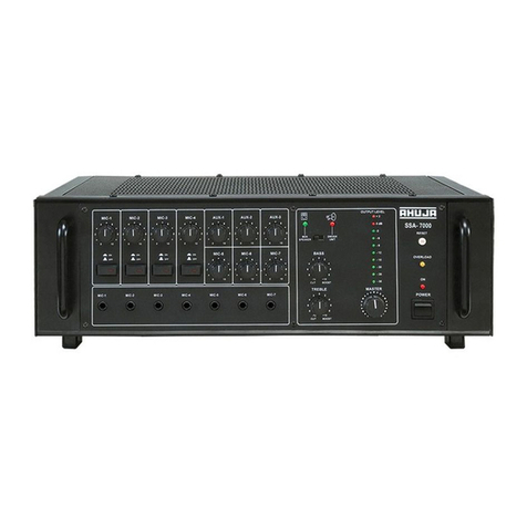
Ahuja UBA-800DP User manual

PA POWER AMPLIFIER
UBA-800DP
800W RMS / 1050W Max.
®
8Thank you for purchasing the AHUJA PAAmplifier.
8Please read this manual thoroughly before making connections and turning on the power.
Following the instructions in this manual will enable you to obtain optimum performance from your
new AHUJA PA Amplifier.
8Please retain this manual for future reference.
PAAmplifier

2
UBA-800DP
Read the Instructions: Please read all the instructions in this section carefully before installation or use of the
product.Allthesafetyinstructionsmustbefollowed.
RetaintheInstructions:PleaseretainthisInstructionManualforfuturereference.
This symbol, wherever it appears, alerts you to the presence of uninsulated hazardous voltage that
maybesufficienttoconstituteariskofelectricshock.Externalwiringtoanyterminalmarkedwiththis
symbolmustbedonebyatrainedandinstructedpersononly.
This symbol, wherever it appears adjacent to a component, alerts you that the concerned
componentcanonlybereplacedbyanotheroftheexactsamespecifications.
WARNING
lTo reduce the risk of electric shock, do not remove the top cover. No user serviceable parts inside. Refer all
servicingtoqualifiedpersonnelonly.
lBefore replacing any fuse, make sure the set is switched off and disconnected from the AC mains or any other
powersource.Replaceafuseonlywithanotherofexactlysamespecification.
CAUTIONS
Water & Moisture: To reduce the risk of fire or electrical shock, do not expose this set to rain or moisture. Do not
usethisset nearwateror inawet location.Donotkeep any objectfilled withliquid, suchas a vase,on top of this set.
DonotinsertorremovetheACmainsplugwithwethands.
Power Source:Thevoltage&frequencyoftheACmainssupply, towhichthissetcanbeconnected,ismarkedon
therearpaneloftheset.Donotconnectthissettoanypowersourceotherthanthosespecifiedontherearpanel.
Power Cord Protection: Do not cut, kink, damage or modify theAC power cord supplied with this set. Keep the
ACpowercordawayfromheatersandharmfulchemicals.Donotkeepanyheavyobjectonthepowercord.
Operation on Generator: When operating this set on a generator, make sure the set is switched off till the
generatorvoltagehasstabilized.
Ventilation:Thisset should be situated so that its location or position does not interferewith itsproper ventilation.
Donotcovertheventilationholes/slots.Donotinsertordropanythingintotheventilationholes/slots.
Stability:Thissetmustbekeptinastableandflathorizontalposition,andneverinatiltedposition.Donotplacethis
set on an unstable stand, tripod, bracket or mount. Do not use attachments which are not supplied or explicitly
recommendedbythemanufacturer.
Cover Strip:The cover strip of the output terminal strip, must be replaced after making connections. Failure to do
somayresultinexposuretohazardousvoltages.
Earthing: This set must be earthed properly before use.A wire from the Earth terminal on the rear panel must be
connectedtoelectricalearth.
Cleaning: Disconnect this equipment from theAC mains and external battery before cleaning. Clean with a damp
cloth,butdonotallowanyliquidtoentertheset.Donotcleanwithliquidsoraerosols.
Exposure to Heat:Donottouchtheheatsinkswhilethesetisworking.
• Safety Instructions

Contents Page No.
!Features/General Description of Product . . . . . . . . . . . . . . . . . . . . . . . . . . . . . . . . . 4
!FrontPanelControls &Features . . . . . . . . . . . . . . . . . . . . . . . . . . . . . . . . . . . . . . . . . 5
!RearPanelControls& Features . . . . . . . . . . . . . . . . . . . . . . . . . . . . . . . . . . . . . . . . . 6
!MP3PlaybackFacilityControls & Features . . . . . . . . . . . . . . . . . . . . . . . . . . . . . . . . . 7
!Pairingof Bluetooth Device . . . . . . . . . . . . . . . . . . . . . . . . . . . . . . . . . . . . . . . . . . . . . 8
!Interconnections . . . . . . . . . . . . . . . . . . . . . . . . . . . . . . . . . . . . . . . . . . . . . . . . . . . . . 9
!SpeakerConnection Guidelines . . . . . . . . . . . . . . . . . . . . . . . . . . . . . . . . . . . . . . . . 10
!TypicalApplications . . . . . . . . . . . . . . . . . . . . . . . . . . . . . . . . . . . . . . . . . . . . . . . . . 11
!Specifications . . . . . . . . . . . . . . . . . . . . . . . . . . . . . . . . . . . . . . . . . . . . . . . . . . . . . . 12
3UBA-800DP
• Table of Contents

!
performances.
!UBA-800DP is a 800 Watts amplifier which can be connected to various
input sources like a Microphone, PAMixer, CD player, DJ Mixer, Cassette
player,Keyboardetc.
!Built-in MP3 player with remote control and can play USB drive as well as
SD/MMCcard.
!The amplifier comprises of but and boost type Bass and Treble controls
which provides precise and accurate tonal setting of the programme
material.
!LineInputandLineOutputhavebeenprovidedtoenableinterconnections
withotherpoweramplifiers.
!CircuitProtectorDevicehasbeenprovidedwhichsafeguardstheamplifier
againstoverloadandshortcircuit.
!The amplifier is fully protected for variations inAC supply due to Genset /
Mainsfluctuationupto300V.
!Indicator LEDs for Power, Signal, Temp, Overload and Fault conditions
havebeenprovided.
!Easeofoperation,combinedwithserviceaccessibilityhasbeenoptimized
inthedesign.
Designed for use in a wide variety of PA applications and DJ
• Features/General Description of Product
4
UBA-800DP

• Front Panel Controls & Features
1. MP3 Playback Facility 8. OVERLOAD LED
See Page No. 7 & 8. The glowing of this red LED indicates that the
circuit protector has tripped. TheAC mains supply
2. BASS Control to the amplifier is cut-off till the fault is rectified
For attenuating or boosting the low frequency and the reset button is pressed.
signal level with a centre frequency of 100Hz. 9. FAULT LED
3. TREBLE Control The glowing of this red LED indicates that some
For attenuating or boosting the high frequency fault has occurred in the amplifier. The protection
signal level with a centre frequency of 10kHz. circuit then mutes the input signals. The amplifier
4. POWER LED will remain at mute status till the fault is rectified.
The glowing of this red LED indicates that the 10. LED Array
amplifier is switched ON. This indicates the output level of the amplifier.
5. POWER Switch Acceptable output levels are indicated by
Push the top part of the knob to switch the occasional flickering of the 0dB LED. If this LED
amplifier ON. Push the bottom part of the knob to glows continuously then it is advisable to reduce
switch the amplifier OFF. the input signal level either from the signal source
or the amplifier volume controls.
6. RESET Button
This button pops out when the circuit protector 11. MASTER Volume Control
trips. Rectify the cause and press the RESET For adjustment of the overall volume level of the
button for resetting to normal operation of the amplifier.
amplifier. 12. AUX / CD Volume Control
7. TEMPERATURE LED 13. USB Volume Control
The glowing of this yellow LED indicates
excessive temperature of the output devices. The 14. MIC Volume Control
protection circuit then mutes the input signals.
The amplifier will remain at mute status, till the
amplifier cools down to normal temperature.
5UBA-800DP
1 3 4 5
611121314 78910
2
PA POWER AMPLIFIER

16 17 18
21222324
19
20
15
15. 3CoreACMainsCablewithPlug auxiliarysourcelikeaTuner,CassettePlayer,Echo
MixerorAudioMixingConsoleetc.
16. EarthTerminal AuxInput should be used only when the CD Inputis
17. SPEAKERTerminalBlock(2 ,4 &8 ) notconnected.
Forconnectinglowimpedancespeakers. 21. MICInputJackSocket
18. CDInputRCASockets For accepting unbalanced signal from a low
For connecting stereo inputs such as a CD player, impedancemicrophone.
DJMixeretc. 22. LINEInputJackSocket
CDInputshouldbe used only whentheAux Input is For connecting an external Mixer to enhance the
notconnected. numberofinputs.
19. AUXInputJackSocket(250mV) 23. LINEOutputJackSocket
For accepting an unbalanced signal from an For connecting to a booster amplifier to obtain
auxiliary source of higher output mixer, CD Player combinedhigherpoweroutput.
etc. 24. DCFusesRating25Amp250V(T25AL)
20. AUXInputJackSocket(100mV) These protect the amplifier from any excessive
For accepting an unbalanced signal from an currentflow.
6
• Rear Panel Controls & Features
UBA-800DP
Caution
!The equipment must be earthed properly before operating it to avoid electric shock. A wire from the Earth
Terminalmustbeconnectedtoelectricalearthforsafeoperation.

• MP3 Playback Facility: Controls & Features
7UBA-800DP
A. VOL+: ToincreasevolumelevelofMP3player. H. IR Sensor: Picks up signal from the Remote control.
Point the Remote control toward this sensor for best
B. VOL-: TodecreasevolumelevelofMP3player. results.
C. PLAY/PAUSE: Press PLAY/PAUSE once to I. Mode: To select USB, SD or Bluetooth mode. The
Pauseifmusicisalreadyplaying.PressPLAY/PAUSE defaultconditionoftheamplifierisBluetoothmode.
againtoresumeplaying. J. LED Display: Instantly displays 3 digits of the track
D. USBConnector: InserttheUSBdrivehere.While selected play to i.e 001 to 999. During play, display
inserting USB drive into the USB connector, hold the thetimedurationofthetrackplayed.
USB drive in such a way that hollow part of the USB Remote Control
driveisdownwardsasshowninFigure. K. Power: Press once to switch off MP3 digital player,
pressagaintoswitchON.
L. Number key 0 to 9. To choose the track number to be
played.
M. : Toselecttheprevioustrack.
N. MODE:ToselectSDorUSBifbothareinserted.
O. : Presstoselectthenexttrack.
Any forceful insertion in wrong direction will damage P. Pressoncetorepeat the songbeingplayed. Press
theconnector. againtorepeatallthesongs.
E. SD/MMC Card Connector: Insert the SD/MMC Card Q. STOP:Presstostopthetrackbeingplayed.
into the slot to play. When taking out the card, pull the
cardtotakeout. R. Vol:PresstodecreasethevolumeofDigitalPlayer.
WhileinsertingSD/MMCcardintotheslot,ensurethat S. Vol: PresstoincreasethevolumeofDigitalPlayer.
the card is inserted in such a way that all pins are T. MUTE: Pressoncetomutethesound,pressagain
facing upward and cut is towards left as shown in theresumethesound.
figure. U. PLAY/PAUSE: Press Play/Pause once to Pause
when music is already playing. Press Play/Pause
againtoresumeplaying.
V. Battery Replacement: Pull out the battery tray and
replace the battery with positive electrode facing
upwards as shown in fig. below. Push the battery
compartmentbackto theclose position.Use CR2025
F. Next: Press NEXT to select next forward music orequivalentlithiumcoincell.
track.PressingNEXTrepeatedlywillmovethesystem
tosuccessivelynextforwardtracks.
G. Prev: Press PREV to Select the previous track.
Pressing PREV repeatedly will move the system to
successivelyprevioustracks.
Remote Control
Pull Battery
Tray
Push to Lock
IJ
A
E
F
G
H
D
B
C
K
M
N
O P
V
Q
R
S
T
U
L
Hollow Face
Solid Face
Cut
Connecting Pins

• Pairing of Bluetooth Device
8UBA-800DP
SWITCH ON the amplifier in use. The Default condition of the MP3 digital
PlayerisBLUETOOTHmode.Thedisplayshows"bLUE.
To play the MP3 programme from mobile phone or laptop, the PAIRING of
theBluetoothdevicesofmobilephone& Amplifier isnecessary.
Pairingisdoneasfollow:-
SELECT the Bluetooth option in Mobile Phone or laptop & follow the
instructionasappearonmobile/laptop.
Normallyfollowinggeneralinstructionsarefollowed:
PressACTIVATE /ON/DISCOVERABLE/SEARCH, etc, as applicable in the
mobilephoneorlaptopused.
The mobile phone or laptop starts searching for the new Bluetooth device.
The moment either TDMO11 or BTSPEAKER appears on the mobile phone
or laptop, select the new device i.e. TDM011 or BTSPEAKER and press OK
orallowittoappearonmobile.Systemisreadytouse.
In some mobiles, it asks for a code to allow access. The press 0000 and
follow the steps, like pressing "OK", "Allow once", "Allow always" etc. and
makethedevicereadyforuse.
Select the MP3 programme from mobile phone or laptop and press PLAY.
The same song starts playing on the Ahuja Amplifier. We can SELECT
Volume,FF,Rewind,Play/PausefunctioneitherfromkeysontheAmplifieror
throughRemoteControl.
Note: It is not necessary that all functions of remote control will be activated
throughBluetoothandcompatibilityvaries from mobiletomobile.

9
• Interconnections
UBA-800DP
Program Speakers Booster Amplifier
Aux Input (100mV)
CD Input
CD Player
Line Out Line In
Microphone
Wireless Microphone
Mic Input
8 /4 /2
UBA-800DP (Rear Panel)
Echo Mixer
POWER
DMX-40
ECHO-REVERB
Cassette Player
TP-50
Keyboard
DJ-MIXER
1 2
1 2
DJ Mixer
PAAmplifier
AMX-812
PA Mixer
Aux Input (250mV)
USB
(ON FRONT PANEL)
!The amplifier can be placed as a tabletop unit. The amplifier uses an
efficient forced cooling arrangement, therefore, the amplifier should be
situatedsothatthefrontandrearventilationslitsarenotobstructed.
!Do not keep the amplifier very close to a wall so that air flow through the
openinginthebackplateisobstructed.
!TheamplifiermustbepoweredthroughanACearthedmainsoutlet.
!All connections must only be carried out or changed with the amplifier
switchedOFF.
!Toavoid loud switching noise, always switchONthepoweramplifierafter
all other units of the audio system have been switched ON. After
operation,switchitOFFfirstandthentheotherunits.
!The connection diagrams that follow, display the typical types of input
sources (Mic, Keyboard, Cassette Player, DJ Mixer, CD Player, USB
player etc.) and box speakers which can be connected to the amplifier.
For correct connections and operation check the specifications of the
connectedequipment. (Refer to page 9 for illustration)

UBA-800DP is a high-powered amplifier.
madetoavoiddamagetotheamplifierorspeakers.
LowImpedance SpeakerConnections
!Box type Speakers can be directly connected to Com-2
/4 /8 TerminalStrip.
Connecting Four SAX-300DX Speakers
The four SAX-300DX Speakers (each speaker has 8
impedance) should be wired in parallel as shown in
figure. The resulting impedance of the speaker system
will be 2 . The speaker system should be connected to
the2 tapoftheamplifier.
ConnectingThree SRX-500Speakers
The three SRX-500 speakers (each speaker has 8
impedance) should be wired in parallel as shown in
figure.Theresultingimpedanceofthespeaker system is
2.66 . Thus they should be connected to the 2 tap of
theamplifier.
Connecting Four SPX-400 Speakers
The four SPX-400 speakers (each speaker has 8
impedance) should be wired in parallel as shown in
figure.Theresultingimpedanceofthespeaker system is
2 . Thus they should be connected to the 2 tap of the
amplifier.
ConnectingOneSWX-650 Subwoofer
One SWX-650 subwoofer system has an impedance of
8 . Thus it should be connected to the 4 tap of the
amplifierasshowninthefigure.
Therefore it is very important that correct loudspeaker connections are
• Speaker Connection Guidelines
10
IMPORTANT
!Speakers should be connected only to either COM-2 or COM-4 or COM-8 terminals as illustrated
abovebutnevertomorethanonesetofterminals.
UBA-800DP
COM 2 4 8
SAX-300DX
8
Resultant Impedance = (8 / 4) = 2
COM 2 4 8
+
-
SAX-300DXSAX-300DXSAX-300DX
888
+++
---
Resultant Impedance = (8 / 4) = 2
COM 2 4 8
+
-
8
SPX-400
+
-
8
SPX-400
+
-
8
SPX-400
+
-
8
SPX-400
COM 2 4 8
+
-
8
SWX-650
Resultant Impedance = (8 / 3) = 2.66
COM 2 4 8
+
-
8
SRX-500
+
-
8
SRX-500
+
-
8
SRX-500

11
• Typical Applications
ConnectingTwoUBA-800DPToMakeA 1600W MonoSystem
1. Insert USB or connect the output of the CD Player to the CD Input of the
firstUBA-800DPusingapatchcordwithRCAplugsatbothends.
2. Connect the Line Out of the first UBA-800DPto the Line In of the second
UBA-800DP usingapatchcordwith¼”phoneplugsatbothends.
3. Loudspeaker connections to both the amplifiers should be done
independently. Each amplifier is connected to a speaker stack which
comprisesoffourSAX-300DXs.
4. Thefourspeakersineachstackwillbewiredtogetherinparallel(resulting
impedance is 2 ) and connected to the COM and 2 tap of their
respective UBA-800DPs.
5. Finally, when operating the system, any adjustment in the overall tonal
quality of the sound can be made through the Bass & Treble of the first
UBA-800DPonly.
6. This MONO system is capable of delivering output power of 1600W at
10%THD which is suitable for various indoor as well as outdoor
applications.
UBA-800DP
2
COM
UBA-800DP (Second)
Line In
2
COM
Line Out
CD Player
R
L
CD Input
UBA-800DP (First)
8
+
-
4 × SAX-300DX
888
+++
---
4 × SAX-300DX
8
+
-
888
+++
---
USB
(ON FRONT PANEL)

• Specifications
TRUSOUND PVT. LTD. C-89, Sector IV, Noida, Gautam Budh Nagar-201 301 (UP)
Regd. Office : 125E, Okhla Industrial Estate, New Delhi-110 020
Tel.: +91-120-4665665 Fax : +91-120-4665621
E-mail: [email protected]
Design and Specifications are subject to change without notice owing to continuous product up-gradation. Technical specifications are subject to production tolerances.
We cannot be held responsible for printing errors, should they occur. is a registered trademark of Ahuja Radios in India and other countries.
© Copyright Ahuja Radios, 2013. All rights reserved.Any unauthorized reproduction or use of logos, images or design elements is strictly prohibited by law.
No part of this compilation may be reproduced in any manner or translated without written permission.
E. & O. E. 0K/12/13
MODEL UBA-800DP
Power Output 1050W RMS Max.
800W RMS at 10%THD
750W RMS at 5% THD
700W RMS at 2% THD
Output Regulation 2dB no load to full load at 1kHz
Input Channels 1 × Mic 1mV / 4.7k
(Mic source impedance 50 to 1k )
1 × Aux 100mV / 470k
1 × Aux 250mV/20k
1 × CD 250mV / 20k
Line Input 1V / 10k
MP3 Playback Built-in MP3 playback facility (USB, SD and MMC card)
Remote Control provided
Frequency Response 50Hz–18,000Hz ±3dB
Signal to Noise Ratio 60dB
Tone Controls Bass (100Hz) : ± 8dB
Treble (10kHz) : ± 8dB
Line Output 1V/1k
Output Taps for Speaker Matching 2 , 4 & 8
Power Supply AC: 220-240V 50/60Hz
Protections AC: Circuit Protector 8Amp.; ± DC: 2 x 25Amp. (T 25AL)
Protected against high AC mains voltage, overload and temperature
AC Power Consumption 1500 VA
Dimensions W482 × H186 × D530 mm
Weight 37.2kg approx.
Table of contents
Other Ahuja Amplifier manuals

Ahuja
Ahuja SSA-1000 User manual

Ahuja
Ahuja BTZ-20000 User manual

Ahuja
Ahuja SSA-160 EM User manual

Ahuja
Ahuja DPR-125 User manual

Ahuja
Ahuja SSA-7000 User manual

Ahuja
Ahuja LXA-7600 User manual

Ahuja
Ahuja BTZ-10000 User manual

Ahuja
Ahuja SSA-250 M User manual

Ahuja
Ahuja UBA-500M User manual

Ahuja
Ahuja PA-400S User manual

Ahuja
Ahuja BTZ-5000 User manual

Ahuja
Ahuja SSA-250 M User manual

Ahuja
Ahuja UBA-500DP User manual

Ahuja
Ahuja PAM-3001 User manual

Ahuja
Ahuja DXA-3502 User manual

Ahuja
Ahuja SSB-80 M User manual

Ahuja
Ahuja DPA-370 User manual

Ahuja
Ahuja TZA-1200 User manual

Ahuja
Ahuja TZA-4000 DP User manual

Ahuja
Ahuja SPA-10000 User manual