January 2004 - 2- Public Server/Manuals/UAN Pneumatic Nutrunner
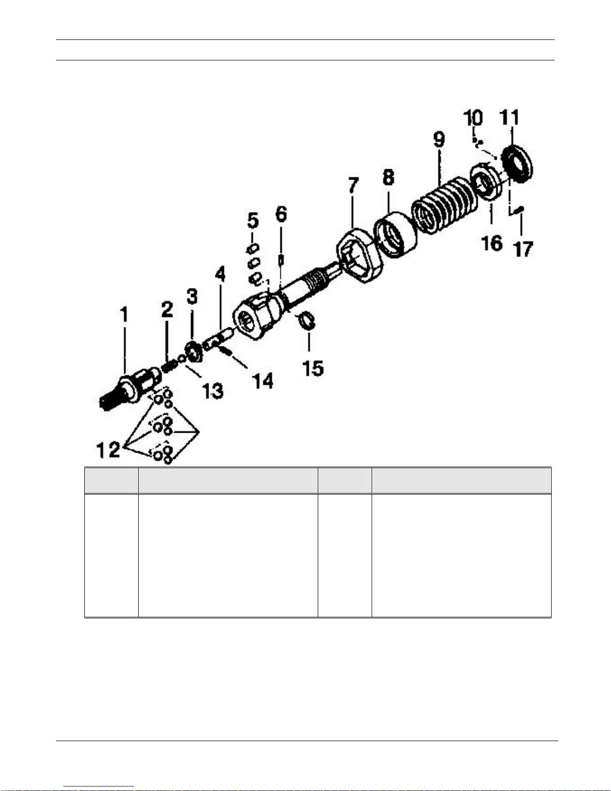
Disassembly and Reassembly of Clutch UAN-611R and 701R
Disassembly:
1. Separate the clutch casing (left hand) from the gear casing and remove the clutch assembly.
2. Remove the regulator screw by inserting a Phillips driver between it and the stopper and turn the Phillips
driver counter-clockwise to remove the regulator screw.
3. Remove the stopper being careful not to lose the pin that locks the stopper to the cam guide.
4. Remove the torque spring and spring setter from the cam guide.
5. Remove the cam rollers, cam ring, balls, and cam from the cam guide.
6. Remove the ball and spring from the cam.
7. Lift the hooked end of the notch pin band out of the hole in the cam guide and slide it around the cam guide
until the end of the notch pin is exposed. Now remove the notch pin and pilot pin from the cam guide.
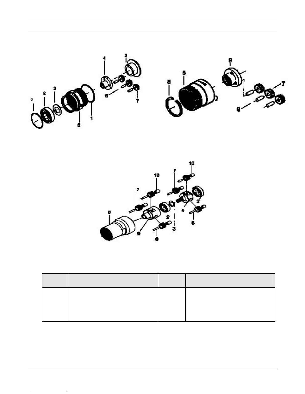
Inspection:
1. CAM:Inspect the cam lobes for grooving where they push the balls out against the cam ring.
PILOT PIN: Inspect the shoulder that is pushed up against the notch pin for rounding.
NOTCH PIN:Inspect the ends for rounding.
BAND:Inspect the band. The band should set down in the groove of the cam guide so that space
from the band to the outside of the cam guide is the same all the way around.
BALLS: Inspect for pitting.
2. Inspect all springs for tension.
3. Replace all worn parts.
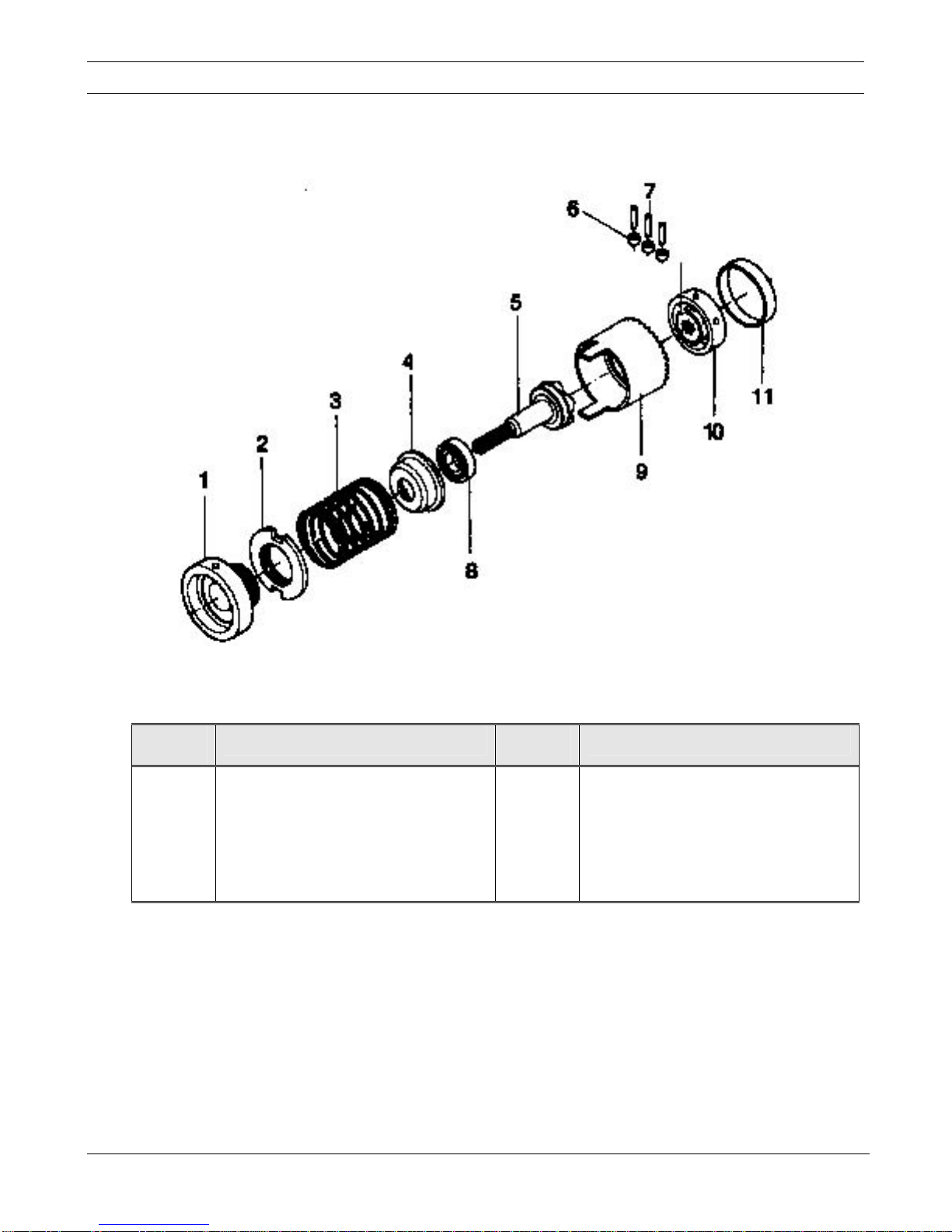
Reassembly:
1. Install the spring and ball into the cam.
2. If replacing the pilot pin, press the new “G” pin into the pilot pin. Install the pilot pin “G” pin out into the
cam guide.
3. Install the cam into the cam guide. Rotate the cam. The lobe on the pilot pin should appear in the hole that
the notch pin goes into at the same time that the lobe comes up in the slot of the cam guide. If it does not
pull the cam out halfway and rotate 180°, push it back into the cam guide and try again. Note:The lobe on
the pilot pin and the lobe on the cam need to line up.
4. Holding the cam and cam guide together, put grease into each of the slots in the cam guide.
5. Install two of the larger balls into the slot of the cam guide and put a shot of grease on top of the balls. On
the 701R, install the three smaller balls. On the 611R, install the three balls of the same size on top of the
two larger balls.
6. Install the cam ring over the balls and install the cam roller into the slot on the cam guide and push them
down against the balls. Install the spring setter over the cam roller.
7. Install the notch pin and notch pin band. If you are replacing the band, slide the Jig #471-670-7-1 down
over the cam guide and install the new band.
8. Install the torque spring, stopper, pin, and regulator screw.