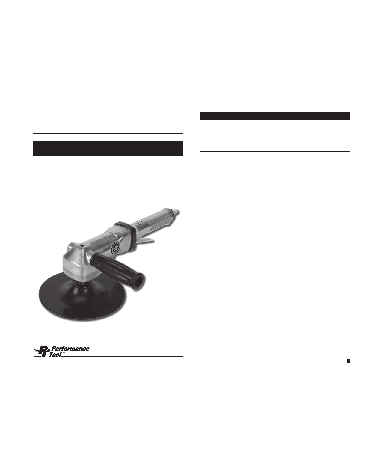
manuals.online logo
Brands
  1. Home
  2. •
  3. Brands
  4. •
  5. Performance Tool
  6. •
  7. Nail Gun
  8. •
  9. Performance Tool M643 User manual

Performance Tool M643 User manual

WARNING!
READ, UNDERSTANDAND FOLLOW ALL INSTRUCTIONSAND WARNINGS BEFORE
OPERATING THIS TOOL. FAILURE TO DO SO MAY RESULT IN PERSONAL INJURY
AND/OR PROPERTY DAMAGEAND WILL VOID WARRANTY.
7 in. Angle Sander
OWNER’S MANUAL
Stock Number M643
sPecIfIcAtIoNs:
Air pressure (P.S.I.): .............................................90
Average air consumption (C.F.M.): ..................................12
Free speed (R.P.M.): .........................................4,500
Spindle Thread: ............................................5/8 - 11
Air inlet (N.P.T.): ...............................................3/8
Hose size (I.D.): .............................................1/2 in.
Weight (LBS.): ...............................................4.19
Specifications are subject to change without notice.
3
IMPORTANT SAFETY INFORMATION
WARNING!
ReAD, uNDeRstAND AND foLLoW ALL INstRuctIoNs AND
WARNINGs BefoRe oPeRAtING tHIs tooL. fAILuRe to Do
so MAY ResuLt IN PeRsoNAL INJuRY AND/oR PRoPeRtY
DAMAGe AND WILL VoID WARRANtY.
1. Use only paper sanding disks with the proper adhesive. Read, under-
stand and follow all adhesive manufacturers’ directions. Do Not use
cLotH BAcKeD sANDING DIsKs WItH tHIs tooL.
2. Make sure sanding pad RPM rating matches Free Speed rating
of this tool.
3. Wear a dust mask while operating this tool. Read, follow and un-
derstand manufacturers instructions on paint, primer, paint preps,
glazing, body ller, etc. for additional respirator and ventilating
requirements.
4. Always use approved eye and ear protection when using air powered
tools. If raising dust/debris, wear a suitable mask. Do not wear loose
clothing or jewelry.
5. Always operate tool a safe distance from yourself and others in the
work area. Keep footing and balance at all times.
6. Make sure work piece is secure to allow safe operation of the tool with
both hands. Do not hold the work piece in your hand, lap or against
any part of your body.
7. Make sure trigger is in the “off” position before connecting or discon-
necting the tool from air source. Disconnect tool from air source
before changing accessories, performing service and when not in use.
8. Follow air source manufacturer’s directions for connection of regula-
tors, lters and other accessories to air source. Do not install quick
couplers directly at tool air inlet. This causes inlet failure due to
excess weight and vibration. Use a whip hose between tool and quick
couplers.
9. Do Not oVeRLoAD! Do not force tool. Match tool capacity to work
load requirement. Use tool within its rated capacity and only for its
designated purpose. Overloading air tools will cause premature wear
and/or permanent damage of internal and external drive parts and will
void warranty.
10. Inspect hoses and ttings for wear and damage prior to using tool.
Do not carry or drag tool by the air hose. Keep air hose free from
obstruction, twisting and binding.
45
OPERATION
Pad
Handle
Air Inlet
Trigger
ASSEMBLY
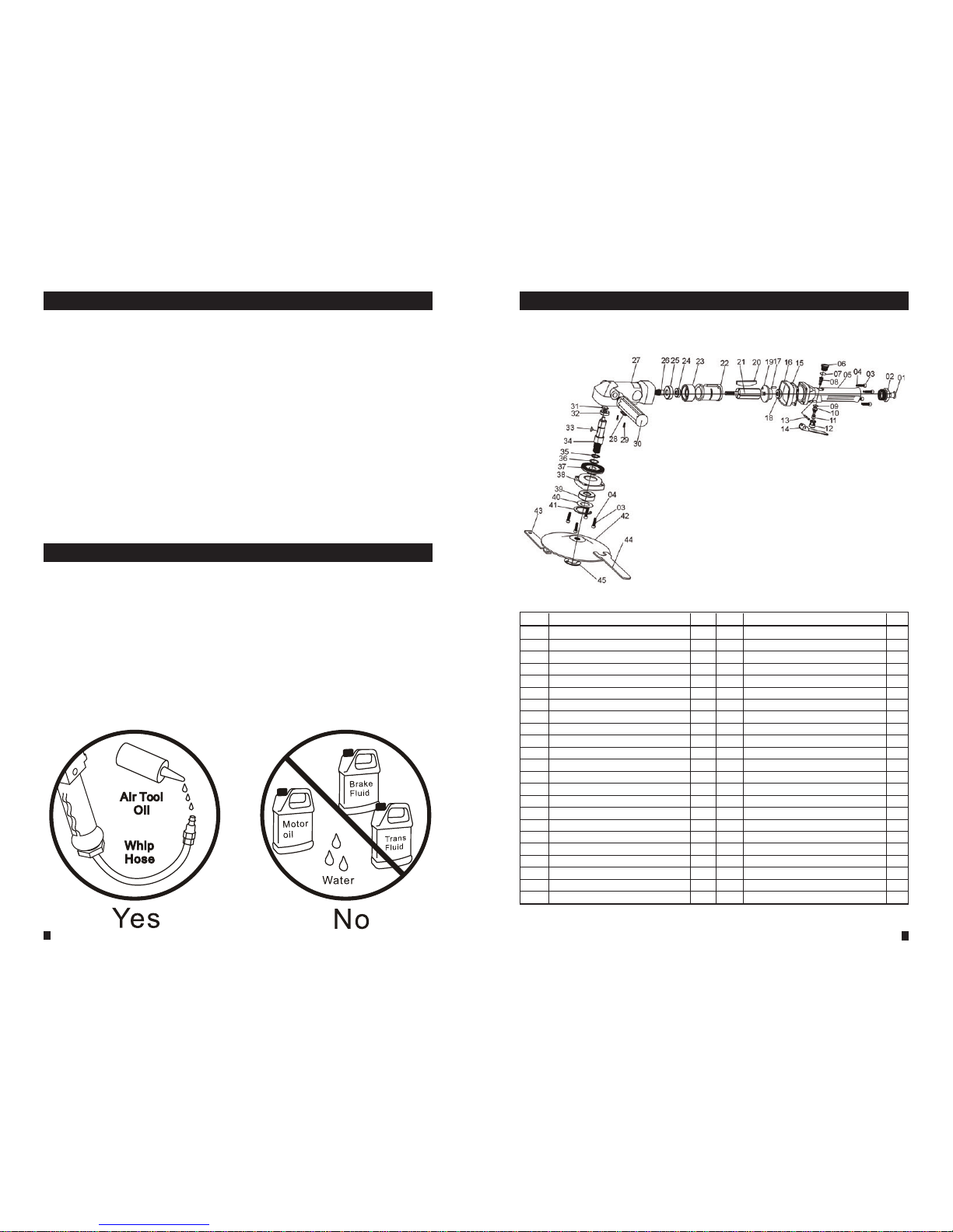
1. Thread the Side Handle (30) into the side of the Gear Housing (27) until tight.
2. Thread raised side of Pad onto Lock Nut (45).
3. Place the grinding wheel or backing pad onto Lock Nut (45).
4. Thread Sealing Ring (5) onto Lock Nut (45) making sure at edge faces out.
5. Place Wrench (44) on Arbor (34) and the Lock Nut Wrench (43) on the Lock Nut
(45) and tighten.
SETUP
1. Designate a clean and well-lit work area. Work area must not allow access by children
or pets to prevent distraction and injury.
2. Route the air hose along a safe path to reach the work area without creating a tripping
hazard or exposing the air hose to possible damage. Make sure air hose is long
enough to reach work area with enough slack to allow free movement while working.
3. Secure loose work pieces using a vise or clamps to prevent movement while working.
4. Make sure there are no hazardous objects (such as utility lines or foreign objects)
nearby that will present a hazard while working.
5. If an automatic oiler is not used, put a few drops of Pneumatic Tool Oil into tool at air
inlet connection before use. Add a few more drops after each hour of continual use.
6. Set the compressor to 90 PSI.
OPERATION
Sanding Instructions:
1. Position the sanding disc (sold separately) in the center of the Pad, making
sure there is equal overhang on the disc.
2. Grip tool with both hands and place onto the area to sand.
3. Squeeze the Trigger (14). You can vary the speed of the tool to suit your
needs by varying the amount of pressure applied.
4. Move tool in a uniform pattern, either up or down or side to side to ensure
even sanding.
5. Periodically check tool for any potential disc wear. Replace used disc when
necessary.
Grinding Instructions:
1. Attach grinding wheel as indicated in Assembly.
2. Grip tool with both hands and place onto the area to sand.
3. Squeeze the Trigger (14). You can vary the speed of the tool to suit your
needs by varying the amount of pressure applied.
4. Move tool in a uniform pattern, either up or down or side to side to ensure
even grinding.
5. Periodically check the tool for any potential wear. Replace used grinding
wheel when necessary.
Polishing/Bufng Instructions:
1. Attach a polishing bonnet (sold separately) and apply a small amount of
the appropriate polishing compound onto the bonnet in a circular (or swirl)
fashion.
3. Grip toool with both hands and place tool onto the area you wish to polish.
4. Squeeze trigger (14) halfway down. Move the tool in a random pattern.
CAUTION! Do not polish in one position for more than a few seconds.
5. Once you've covered the desired area, stop and replace bonnet with a new
bonnet for bufng operation.
6. Avoid polishing body part edges. Use hand force to prevent possible damage
to auto body nish.
7. Buff polished area the same way, applying light pressure and moving in a
random pattern until the compound has been removed.
8. Use a clean, lint-free cloth to remove any compound from crevices that could
not be reached with Tool.
9. If the tool requires more force to accomplish the task, verify that the tool re-
ceives sufcient, unobstructed airow (CFM) and increase the pressure (PSI)
output of the regulator up to the maximum air pressure rating of this tool.
CAUTION! To prevent tool and accessory failure, resulting in injury: Do not
exceed tools maximum air pressure rating.
10. If tool still does not have sufcient force at maximum pressure and sufcient
airow, a larger tool may be required.
11. To prevent accidents, turn off the tool, detach the air supply, safely discharge
air pressure, and release the trigger. Clean external surfaces of the tool with
clean, dry cloth, and apply a thin coat of tool oil.
Then store the tool indoors out of children's reach.
6
Oil tool before each use. 4 to 5 drops of a good grade Air Tool Oil
placed in the air inlet is sufficient. Use proper air pressure and
CFM rating listed for this tool.
Drain water from hoses and compressor tank. Water in the
air supply line will cause gumming and loss of power. Clean the
air lter on the supply line and ush the tool with gum solvent or
a 50/50 mix of air tool oil and kerosene. It may be necessary to
disassemble the tool to properly clean and re-lubricate.
LUBRICATION & MAINTENANCE
AIR SOURCE
Clean air of correct air pressure is recommended for the power
supply for this tool. A maximum of 90 PSI at the tool is recom-
mended for most air tools of this class. Check specications sec-
tion for recommended pressure. (Depending on length of air hose
and other circumstances, air pressure at compressor may need to
be increased to 100 PSI to ensure 90 PSI at the tool.)
Water in the air hose and compressor tank contributes to reduced
performance and damage of the air tool. Drain the air tank and l-
ters before each use and as necessary to keep the air supply dry.
Hose length over 25’ causes loss in line pressure. Increase hose
I.D. or increase compressor pressure to compensate for the pres-
sure loss. Use an in-line pressure regulator with gauge if air inlet
pressure is critical.
7
No. DESCRIPTION QTY No. DESCRIPTION QTY
1. Air Inlet Cover 1
2. Air Inlet Screw 1
3. Screw 8
4. Washer 8
5. Body 1
6. Screw 1
7. O-Ring (15 x 2.4) 1
8. Valve Spring 1
9. O-Ring (9.6 x 2) 1
10. O-Ring (8 x 1.6) 1
11. Valve Stem 1
12. Valve Cover 1
13. Trigger Pin 1
14. Trigger 1
15. Gasket 1
16. Ring 1
17. Cylinder Pin 1
18. Bearing 1
19. Back Cover 1
20. Rotor 1
21. Rotor Blade 4
22. Cylinder 1
23. Front Cover 1
24. Bearing 1
25. Bearing 1
26. Gear 1
27. Gear Housing 1
28. Exhaust Deflector 1
29. Screw 2
30. Side Handle 1
31. Dust Cover 1
32. Bearing 1
33. Woodruf Key 1
34. Arbor 1
35. Retaining Ring 1
36. Wave Washer 1
37. Gear 1
38. Housing Cap 1
39. Bearing 1
40. Bearing Washer 1
41. Circlip 1
42. Sanding Pad 1
43. Lock Nut Wrench 1
44. Wrench 1
45. Lock Nut 1
PARTS LIST
INSUFFICIENT POWER:
Probable Cause Solution
Dirty or clogged air passages......... Flush and lubricate tool, drain air tank and supply line
Insufficient air supply...................... Increase line pressure, Make sure compressor
matches tool's air pressure and consumption needs
Air leakage...................................... Use PTFE tape at all fittings and joints. Check tool for
worn or damaged O-rings & seals.
Worn/damaged wear & tear parts... Replace as necessary.
Tool matching ................................. Be sure you are using a tool suited for the torque
requirements of the job at hand.
TROUBLESHOOTING
LIMITED WARRANTY
PERFORMANCE TOOL® extends only the following warranties, and only to original retail purchasers. These war-
ranties give specic legal rights. Except where prohibited by local law, the law of the State of Washington governs
all warranties and all exclusions and limitations of warranties and remedies. There may be other rights which vary
from state to state.
PERFORMANCE TOOL® warrants the product to be free from defects in materials and workmanship under
normal use and service. A defective product may be returned for a free replacement within 90 days from the date
of pur-chase, provided that product is returned to
place of purchase immediately after discovery of defect. After 90 days and up to one year from date of purchase,
PERFORMANCE TOOL® will replace at no charge any parts which our examination shall disclose to be defective
and under warranty.
These warranties exclude blades, bits, punches, dies, bulbs, fuses, hoses, and other consumables which must be
replaced under normal use and service. These warranties shall not apply to any product or part which is used for a
purpose for which it is not designed, or which has been repaired or altered in any way so as to affect adversely its
performance or reliability, nor shall these warranties apply to any product or part which has been subject to
misuse, neglect, accident or wear and tear incident to normal use and service.
PERFORMANCE TOOL® does not authorize any other person to make any warranty or to assume any liability in
connection with its products.
Except for warranties of title and the limited express warranties set forth above, PERFORMANCE TOOL® makes
no express or implied warranties of any kind with respect to its products. In particular, PERFORMANCE TOOL®
makes no implied warranty of merchantability and no implied warranty of fitness for any particular purpose, except
that for goods purchased primarily for personal, family or household use and not for commercial or business use,
PERFORMANCE TOOL® makes an implied warranty of merchantability (and, if otherwise applicable, an implied
warranty of fitness for a particular purpose), but only for the particular qualities or characteristics, and for the dura-
tion, expressly warranted above.
The laws on limitation of implied warranties may differ from state to state, so the above limitations may not apply in
all cases.
PERFORMANCE TOOL® shall not be liable for consequential, incidental or special damages resulting from or in
any manner related to any product, or to the design, use, or any inability to use the product. The sole and exclusive
remedy for a defective product or part shall be the repair, or replacement thereof as provided above. The laws on
limitation of remedies or on consequential, incidental or special damages may vary from state to state, so the
above limitations may not apply in all cases.
Check out the collection of air tools & compressors we offer.

Other Performance Tool Nail Gun manuals

Performance Tool M568DB User manual

Performance Tool

Performance Tool M568DB User manual

Performance Tool M573DB User manual

Performance Tool

Performance Tool M573DB User manual

Performance Tool W1650 User manual

Performance Tool

Performance Tool W1650 User manual

Performance Tool M673 User manual

Performance Tool

Performance Tool M673 User manual

Popular Nail Gun manuals by other brands

WilTec 61859 Operation manual

WilTec

WilTec 61859 Operation manual

Cleco 19RAA02AM2 Service manual

Cleco

Cleco 19RAA02AM2 Service manual

Paslode 3250-F16 TOOL SCHEMATIC AND PARTS

Paslode

Paslode 3250-F16 TOOL SCHEMATIC AND PARTS

Makita AF353 instruction manual

Makita

Makita AF353 instruction manual

Senco FinishPro 18Mg operating instructions

Senco

Senco FinishPro 18Mg operating instructions

Paslode Positive Placement PF150S-PP Operating manual and schematic

Paslode

Paslode Positive Placement PF150S-PP Operating manual and schematic

AllTrade AIR-PLUS 691164 Operation manual

AllTrade

AllTrade AIR-PLUS 691164 Operation manual

HIDfast HIDfast Series installation manual

HIDfast

HIDfast HIDfast Series installation manual

HIKOKI NT 50AE2 (T) Handling instructions

HIKOKI

HIKOKI NT 50AE2 (T) Handling instructions

Parkside PET 25 A1 Operation and safety notes

Parkside

Parkside PET 25 A1 Operation and safety notes

Certa PowerPlus CT20VNLSGNA user guide

Certa

Certa PowerPlus CT20VNLSGNA user guide

Hitachi nv90ag parts manual

Hitachi

Hitachi nv90ag parts manual

Rapid Airtac PBS121 operating instructions

Rapid

Rapid Airtac PBS121 operating instructions

MasterCraft AIR-POWERED BRAD NAILERS operating instructions

MasterCraft

MasterCraft AIR-POWERED BRAD NAILERS operating instructions

Everwin MCN40 Operation and maintenance manual

Everwin

Everwin MCN40 Operation and maintenance manual

Makita DBN500 instruction manual

Makita

Makita DBN500 instruction manual

Bosch GSK 18 V-LI Professional Original instructions

Bosch

Bosch GSK 18 V-LI Professional Original instructions

Interchange NSJH38-34 Operator's manual

Interchange

Interchange NSJH38-34 Operator's manual

manuals.online logo
manuals.online logoBrands
  • About & Mission
  • Contact us
  • Privacy Policy
  • Terms and Conditions

Copyright 2025 Manuals.Online. All Rights Reserved.