Air America VIGILANTE User manual

1
VIGILANTE™
By Air America, Inc.
Congratulations on purchasing your new Vigilante™ second stage regulator! The Vigilante™ is the
proud continuation of the time tested Unireg® series of regulators. Your Vigilante™ has been
meticulously engineered to meet the rigorous demands of todays paintball markers while providing a
lifetime of reliable service at a truly affordable price.
GENERAL INFORMATION
The Vigilante™ is a single stage optional Low Pressure, 50 psi to 450 psi, or High Pressure, 450 to
850 psi, regulator designed to accept inlet pressures up to 1200 PSI. The Vigilante™ is precision machined
from an aerospace grade high tensile strength aluminum alloy, to deliver a safe, constant tournament level
output pressure range. The advanced “Super Gun” flow volume design features of the Vigilante™ out pace
the air/nitrogen flow requirements of the most demanding low pressure/high volume marker in Paintball today.
SAFETY ALERT!!
ALWAYS DE-GAS YOUR SYSTEM

2
PRIOR TO SERVICING OR REPAIRING YOUR REGULATOR.

3
GENERAL INSTALLATION OF THE VIGILANTE™
The Vigilante™ will install into any standard ASA adapter. Air America® has maintained the same
high quality CGA 320 thread profile (ASA adapter thread profile) throughout the UNIREG® series of
regulators.
The use of the appropriate pressure rated steel elbows and disconnects are required when choosing
the hardware to connect your Vigilante™ to your Air/Nitrogen/CO2 system. Many of the fittings that are readily
available in your local hardware store are made of brass or nickel plated brass. While these fittings may be
attractive in price, they pose a serious safety hazard due to an inadequate pressure rating and lack of impact
resistance.
INITIAL ADJUSTMENTS
After attaching the appropriate fittings to your Vigilante™ and having mounted it on your marker the
initial pressure adjustments can be made. Each Vigilante™ leaves the factory preset at 750 PSI. Before
applying pressure to your system, read the manufacturers suggested inlet pressure for your marker. If the
suggested inlet pressure is below 700 PSI or you are not sure of what the required inlet pressure for your
marker is, please follow the steps below and in the next section before making any adjustments.
The delivery pressure to your marker is adjusted by turning the adjustment nut on the top of the
Vigilante™. You will need a 3/16 hex or allen key for this operation. Turning the nut clockwise will increase
the delivery pressure, while turning it counter clockwise will decrease the delivery pressure. Please note that
when you decrease the pressure setting you must cycle your marker several times after each adjustment.
This will allow the previously regulated pressure to be exhausted and allow your system to stabilize at its new
setting.

4
ADVANCED TUNING
If you do not have access to a test manifold to statically set the delivery pressure from your Vigilante™
you may follow the following steps to establish the proper working pressure for your marker. While this
procedure was designed with the Autococker in mind, Steps 2 through 6 apply directly to all other markers that
utilize a second stage regulator.
STEP 1 - Back the hammer spring adjustment nut out to the minimum setting.
STEP 2 - Connect your Vigilante™ system to your marker.
STEP 3 - Turn the delivery pressure on your Vigilante™ down to the “no flow” point. This is achieved
by turning the adjustment nut counter clockwise until the last 3 to 4 threads remain threaded.
STEP 4 - Connect your pressure source and slowly apply gas to your system.
STEP 5 - Utilizing a 3/16 hex key, slowly increase your delivery pressure by turning the adjustment nut
clockwise. Cycle your marker and continue to adjust the delivery pressure until you have just
enough pressure to operate the cocking mechanism properly and the marker sounds like it
will propel a ball.
Autococker owners please skip to STEP 7.
STEP 6 - While shooting over a chronograph, adjust the delivery pressure in 1/4 turn increments until
the desired velocity is attained.
STEP 7 - For Autocockers, while shooting over the chronograph adjust your delivery pressure until you
can maintain a consistent string in the low 200 fps range. At this point further adjustment will
result in either no increase in velocity or a marked decrease. Once you have reached this
stage you have found the balance between the hammer spring and the chamber pressure in
your marker.
STEP 8 - After having achieved this balance, utilize your 3/16 hex to adjust the hammer spring tension
on your Autococker to produce the desired velocity.
This tuning procedure illustrates the importance of having a balanced set of springs in your marker.
The gas pressure in the valve chamber represents stored energy just like the coiled springs in the exhaust
valve and hammer portions of your marker. If your hammer spring is too strong for the chamber pressure
applied, excessively long valve cycles will occur resulting in poor gas efficiency. On the other hand, if it too
weak, the exhaust valve will not open fully resulting in low velocity. Having both elements of spring rate and
chamber pressure in balance is critical to the consistent performance of your marker.

5
PERIODIC MAINTENANCE
Your Vigilante™ regulator has been designed to provide a lifetime of service with a minimal amount of
maintenance. However, the interval for required servicing will vary based on your playing style and the
environment to which it is exposed. Dirt, oil and other foreign objects which are introduced into the system will
effect performance and shorten the service intervals, so proper care must be taken to ensure that common
sense is utilized when cleaning your regulator following use. The following routine maintenance should be
performed to ensure that your Vigilante™ regulator will provide optimum performance.
1. Clean all paint, shell fragments and dirt from the exterior of your Vigilante™ with a soft bristle
brush or cloth.
2. Remove all paint, shell fragments and dirt from the inlet and outlet ports of your Vigilante™.
3. Remove the tournament cap, spring guide, main spring, spacer and piston assembly from the
Vigilante™.
4. Examine the interior of the piston housing for dirt and foreign objects, utilizing a clean cotton swab
remove any debris that is found.
5. Examine the piston and piston o-ring for dirt, scratches and nicks. Clean the assembly with a soft
cloth and place a light coat of oil on the piston surface and the o-ring. NOTE: Do not use grease,
or similar lubricant which is safe for use on Urethane o-rings will suffice.
6. Reassemble the components in the proper order and direction. Refer to the exploded parts
diagram for assembly sequence.
Piston Housin
g
Piston Ad
j
ustment Nu
t
Washe
r
Com
p
ression S
p
rin
g
Tournament Ca
p
S
p
ace
r

6
TROUBLESHOOTING GUIDE
Your Vigilante™ regulator has been engineered to require a minimal amount of servicing. Air
America® will service your regulator under its limited lifetime warranty program upon receipt of your completed
warranty registration. Whether attempting to fix a problem yourself, or when corresponding directly with an Air
America® Technical Service representative, please use the following as a guide to correctly identify the
correct repair procedure.
PROBLEM POSSIBLE CAUSE
No Gas Delivery Obstruction in hose from source
Adjustment nut not properly adjusted
Internal obstruction in regulator
Poor Gas Delivery Output pressure not set high enough for marker
(Shootdown) Regulator piston sticking (lack of lubrication)
Cone spring failure
Poor Gas Delivery
(Erratic output pressure) Regulator piston sticking
Cone spring failure
Regulator seat and valve pin failure
Main spring worn
Output Pressure Creeps Up Dirt or debris in regulator seat
Piston Housing and Gas Body not sufficiently tightened
Damaged regulator valve pin
Regulator Leaks from top Chipped or cut piston o-ring
Output pressure set above 1100 psi
Regulator “creeping” (see above)
Defective or damaged safety in piston assembly

7
SERVICING THE REGULATOR SEAT AND VALVE PIN
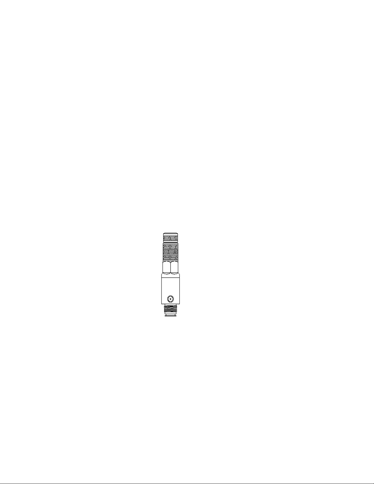
Please refer to the exploded parts diagram shown below when performing maintenance or when
calling in reference to replacement parts.
Your Vigilante™ can be completely disassembled with a 3/16 hex key and a strap or crescent wrench.
Please note: complete disassembly is not required to perform routine maintenance, and should only be done
when servicing the regulator pin and valve seat area.
1. To service these components, it is first necessary to separate the piston housing from the gas
distribution body. Using a strap or crescent wrench and a padded vise, grasp the piston housing and
unscrew it from the gas distribution body.
2. Inspect the regulator seat, valve pin and cone spring for dirt, debris or visible damage.
The sealing face of the valve pin should be clean and free of nicks, scratches and debris. If the valve
pin appears to be marred or bent in should be replace to ensure proper function.
3. The cone spring is a lightly coiled wire spring. It should be free of dirt and debris and should
require a minimal amount of pressure to compress it between your finger tips. If the cone spring
appears to be compressed or has been stretched it should be replaced.
4. The regulator seat can normally be removed from the sealing pocket of the piston housing with
light finger pressure. Should it be necessary to utilize a pick to remove the seat, use caution to
ensure that the sealing pocket does not become scratched or dented. Inspect the regulator seat for
visible obstructions or damage and replace before reassemble. The regulator seat for the Vigilante™
series regulator must be replaced upon each disassembly to ensure proper functioning.
5. When reassembling,
the new regulator seat
should be place in the
sealing pocket of the piston
housing. You will note that
the new seat fits more
loosely than the seat that
you removed. The seating
material used in the
Vigilante™ regulator is
designed to be a
compression fitting and therefore deforms slightly upon proper assembly.
6. Insert the long shaft of the regulator valve pin through the regulator seat into the piston housing.
7. Place the small end of the cone spring on the stud end of the regulator valve pin.
8. Insert the piston housing assembly into the gas distribution body and screw the halves together.
Lubricate the piston housing body o-ring with a light coat of motor oil to prevent the binding of the two
halves.
A properly assembled/tightened regulator should have little to no visible gap between the upper and
lower halves.
Pin S
p
rin
g
Pi
n
Sea
t
Table of contents
Popular Controllers manuals by other brands

Sony
Sony CSP-5000E Service manual

Matsuko
Matsuko Switch Box Installation and operating manual

MICRO-AIR
MICRO-AIR EasyTouch Operation manual

Siemens
Siemens Gamma instabus UP204 Contouch Operating and mounting instructions

Horizon Hobby
Horizon Hobby Spektrum Firma SPMXSER1060 manual

iSMA CONTROLLI
iSMA CONTROLLI MVH56Ex manual