6
RISCHI DI USO IMPROPRIO
1. MAI puntare la pistola in direzione del corpo umano o di animali.
2. MAI superare la pressione o la temperatura massima d’esercizio.
3. Scaricare sempre la pressione dell’aria e del materiale, prima delle opera-
zioni di pulizia, disassemblaggio e di manutenzione.
Altrimenti la pressione residua potrebbe causare ferite al corpo provocate da ope-
razioni scorrette o dall’emissione dei liquidi usati per la pulizia.
4. L’estremità dell’astina è tagliente. Per non rischiare di ferirsi, evitare di toccare
l’estremità dell’astina durante le operazioni di manutenzione.
5. Mai spruzzare prodotti alimentari o chimici con questa pistola.
Altrimenti la miscela di sostanze estranee potrebbe causare la corrosione dei pas-
saggi vernice, con conseguenti danneggiamenti alla pistola e rischi per la salute.
6. Mai modificare la pistola per verniciatura, per evitare danneggiamenti che
potrebbero compromettere la qualità del risultato.
7.
Nel caso di malfunzionamenti, sospendete immediatamente le operazioni di
verniciatura per la ricerca del guasto. Non utilizzare nuovamente il prodotto
finché non si è risolto il problema.
8. Mai entrare nelle aree di lavoro delle attrezzature (come: robot, reciprocato-
ri, ecc.), finché queste non siano state disattivate.
Altrimenti , il contatto con i macchinari in funzione potrebbe essere causa di
incidenti e ferimenti.
3. COLLEGAMENTO
ATTENZIONE
- Per alimentare la pistola utilizzare aria filtrata ed asciutta.
Si consiglia l’uso di un filtro con scarico automatico di condensa ed
essiccatore.
- Quando si utilizza la pistola per la prima volta dopo l’acquisto, regolare
il set guarnizione astina, pulire i passaggi del materiale spruzzando
detergente compatibile per rimuovere l’olio antiruggine.
- Collegare saldamente la tazza alla pistola, per evitare che lo scollega-
mento della stessa durante le operazioni di verniciatura provochi ferite
gravi al corpo.
1.
Collegare saldamente il tubo aria d’alimentazione al raccordo aria
G1/4”(17).
2. Collegare saldamente una tazza adeguata, al raccordo materiale
G1/4”
(15).
3. Detergere i passaggi vernice della pistola con detergente compatibile.
4. Versare la vernice nella tazza, verificare lo spruzzo, regolare la fuoriuscita
del materiale e la larghezza del ventaglio
.
4. COME OPERARE
_ La pressione aria d’atomizzazione varia a seconda del modello ed é indicata
nella tabella delle Specifiche Tecniche.
_ La viscosità della vernice consigliata cambierà secondo le proprietà della
vernice e le condizioni di verniciatura. Éconsigliata una viscosità tra 12 e
23 sec. / Coppa Ford #4.
_ Calibrare la distanza di verniciatura, possibilmente in uno spazio ristretto e
compreso tra i 100-200 mm (3.9-7.9 in).
_ L’assetto della pistola dovrebbe essere mantenuto sempre perpendicolare
alla superficie del pezzo di lavorazione. Inoltre la pistola dovrebbe operare
sempre per linee orizzontali. Eventuali spostamenti della pistola potrebbero
provocare una verniciatura non uniforme.
IT
2. AVVERTENZE DI SICUREZZA
RISCHI DI INCENDI ED ESPLOSIONI
1.
Mai utilizzare SOLVENTI IDROCARBURI ALOGENATI,
che potrebbero causare danni e scioglimento delle parti in alluminio del corpo
pistola, provocati da reazioni chimiche.
SOLVENTI INCOMPATIBILI: cloruro di metile, diclorometano, 1.2-dicloroetano,
tetracloruro di carbonio, tricloroetilene, 1.1.1-tricloroetano.
2. La presenza di fiamme libere e la produzione di scintille è severamente
vietata. I prodotti utilizzati possano essere altamente infiammabili e quindi causa
di gravi incendi. Evitare ogni azione che potrebbe provocare incendi, come fumare,
provocare scintille o qualsiasi rischio elettrico.
3. Collegare correttamente a terra la pistola per verniciatura, utilizzando un
tubo aria conduttivo. (Minore di
1MΩ).
Controllare periodicamente la stabilità della messa terra.
RISCHI PER LA SALUTE
1. Usare la pistola per verniciatura in ambienti, ben ventilati utilizzando la cabi-
na di verniciatura.
Una ventilazione inadeguata o insufficiente potrebbe provocare un’intossicazione da
solventi organici o causare incendi.
2. Indossare sempre indumenti protettivi (occhiali di protezione, maschera,
guanti). Per evitare che il contatto con i materiali irritanti, provochi infiammazione
agli occhi ed alla pelle. Nel caso in cui si verificasse anche il più lieve rischio di
danno fisico, consultare immediatamente un medico.
3. Se è necessario indossare i tappi afonizzanti.
Il livello di rumorosità può superare 85 dB(A) e dipende dalle condizioni d’utilizzo
e dall’area di lavoro.
4. L’utilizzo costante della pistola da verniciatura che prevede una prolungata
pressione manuale sul grilletto della pistola, potrebbe provocare la sindrome
del tunnel carpale. Nel caso di affaticamento della mano, sospendere le operazio-
ni di verniciatura per una breve pausa.
La pistola AIRGUNSA per verniciatura
è in
conformità alla normativa
ATEX 2014/34/EU.
Livello di protezione: categoria II 2G X adatto per uso in Zone 1 e 2.
Marchiatura X: L’elettricità statica deve essere scaricata dalla pistola
e
condotta a terra attraverso la tubazione conduttiva dell’aria come indicato.
Assicurarsi di rispettare SEMPRE, le avvertenze per la
sicurezza, contenute nel suddetto manuale d’istruzione.
Prima di procedere all’installazione, alla messa in funzione,
alla regolazione o alle operazioni di manutenzione, leggere
attentamente il presente manuale d’istruzione, che deve
essere conservato per ogni futuro riferimento.
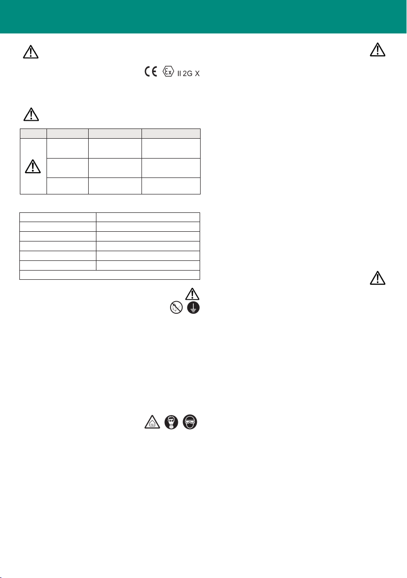
Simbolo
SIGNIFICATO
Livello di pericolo Conseguenze
AVVERTENZE
Situazione potenzial-
mente pericolosa. Seri rischi per la salute
e la vita dell’operatore.
ATTENZIONE
Situazione potenzial-
mente pericolosa. Rischi moderati per il
prodotto e l’operatore.
IMPORTANTE
Situazione potenzial-
mente pericolosa. Danni materiali.
1. SPECIFICHE TECNICHE
AZ3 HTE2 | AZ3 HTE2 AV | AZ3 HTE2 HVLP
Max. pressione d’esercizio aria: 7.0 bar (100 PSI)
Peso g (lbs): (senza tazza) 517 (1.14)
Livello di rumorosità (LAeqT)*: 77.6 dB(A)
Raccordo aria G1/4”M
Raccordo Materiale G1/4”F
Max. Temperatura: Ambiente 5 ~ 40 °C - Aria/Fluido 5 ~ 43 °C
*Punto di misurazione: 1 m dietro la pistola, 1.6 m d’altezza.