MN-754
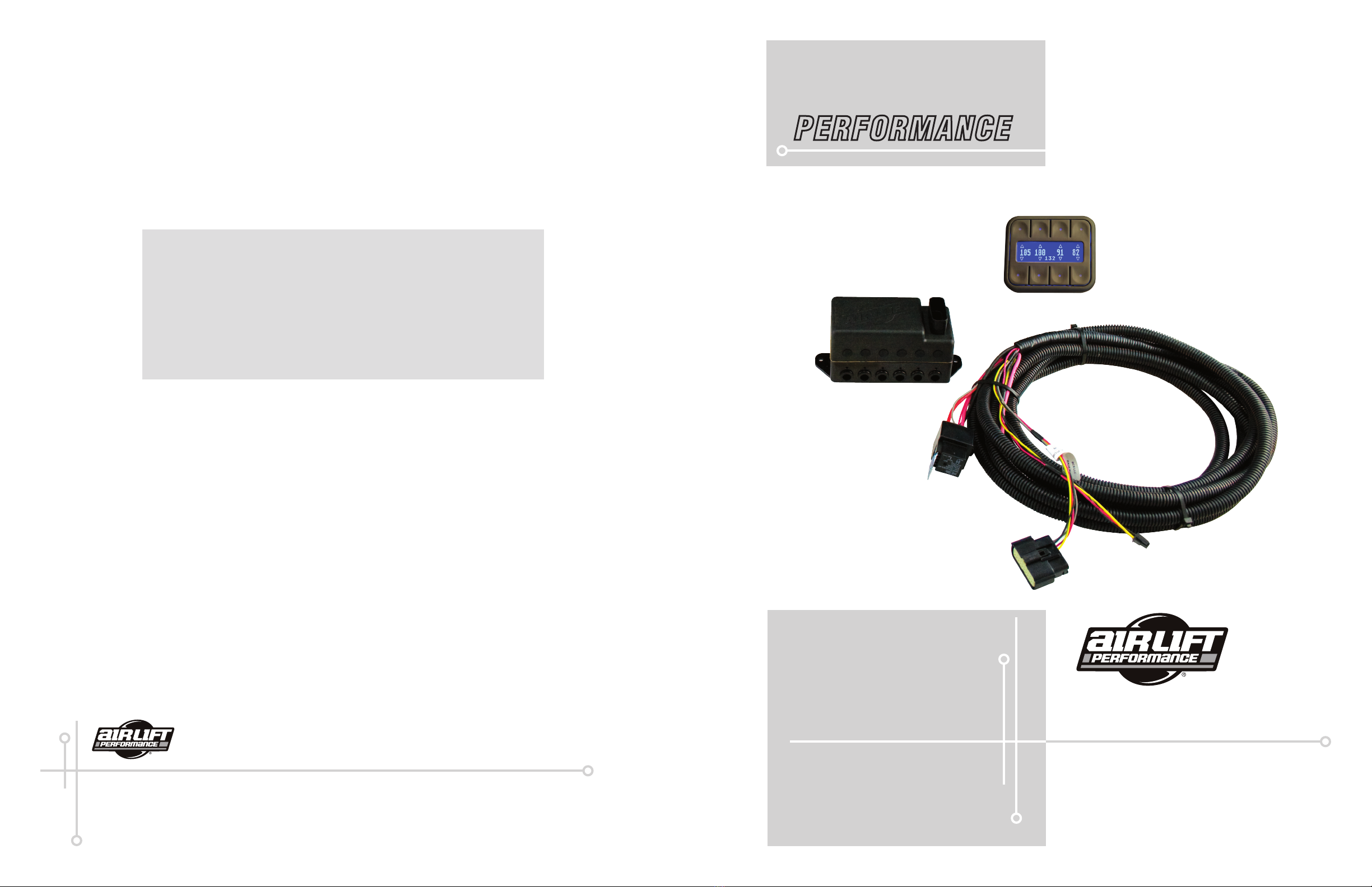
AutoPilot V2AutoPilot V2
MN-754
13 2
Air Lift Company warrants its performance products for one year to the original purchaser
against manufacturing defects one year from the date of purchase when used on cars
and trucks as specied under normal operating conditions. The warranty does not apply
to products that have been improperly applied, improperly installed, or which have not
been maintained in accordance with installation instructions furnished with all products.
The consumer will be responsible for removing (labor charges) the defective product from
the vehicle and returning it, transportation costs prepaid, to the dealer from which it was
purchased or to Air Lift Company for verication.
Air Lift will repair or replace, at its option, defective products or components. A minimum
$10.00 shipping and handling charge will apply to all warranty claims. Before returning any
defective product, you must call Air Lift at (800) 248-0892 in the U.S. and Canada (elsewhere,
(517) 322-2144) for a Returned Materials Authorization (RMA) number. Returns to Air Lift
can be sent to: Air Lift Company • 2727 Snow Road • Lansing, MI • 48917.
Product failures resulting from abnormal use or misuse are excluded from this warranty. The
loss of use of the product, loss of time, inconvenience, commercial loss or consequential
damages is not covered. The consumer is responsible for installation/reinstallation (labor
charges) of the product. Air Lift Company reserves the right to change the design of any
product without assuming any obligation to modify any product previously manufactured.
This warranty gives you specic legal rights and you may also have other rights that may vary
from state-to-state. Some states do not allow limitations on how long an implied warranty
lasts or allow the exclusion or limitation of incidental or consequential damages. The above
limitation or exclusion may not apply to you. There are no warranties, expressed or implied
including any implied warranties of merchantability and tness, which extend beyond this
warranty period. There are no warranties that extend beyond the description on the face
hereof. Seller disclaims the implied warranty of merchantability. (Dated proof of purchase
required.)
Warranty and Returns Policy Installing the AutoPilot V2 Kit
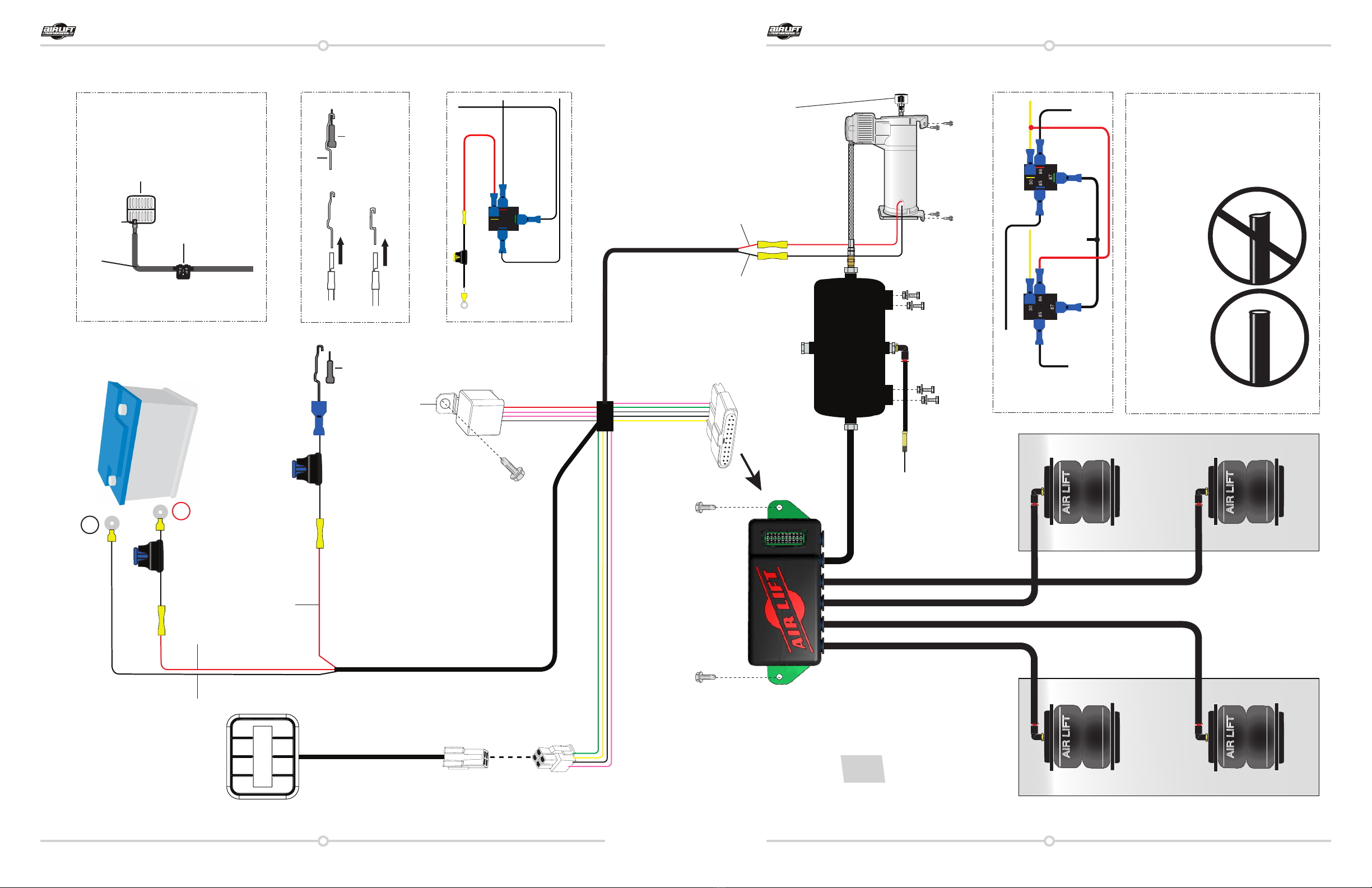
INSTALL COMPONENTS
LAYOUT: plan component location rst. Prior to mounting components, check to make sure
the electrical harness connections will reach the manifold and compressor, the compressor
leader hose will reach the tank, and the plumbing will route cleanly through the vehicle.
Be sure to install all components as far as possible from any heat sources. Plan and prepare
harness and plumbing routing thru the vehicle: eliminate all sharp edges that could chafe,
use grommets when passing through compartment walls.
Air Compressors ingest moisture and will deposit it inside the tank. The AutoPilot V2 system
does not include moisture separators or lters, and does require periodic tank moisture
removal. If using an Engine Driven compressor, proper oil and water ltration must be added
as these compressors will quickly contaminate the air suspension system.
Compressor
• Prepare Compressor Intake: if inside vehicle, attach lter to port on end of compressor
(Fig. 10). If compressor is located outside vehicle, snorkel inlet lter to dry location
• Center punch and drill four ¼” diameter holes using the compressor itself as a template
• Attach using hardware supplied with compressor
Manifold
• Position manifold in its desired location: make sure manifold mount surface is at
• Fasten using the two provided self-tapping screws. If mounting surface not at, add
washers to space the manifold up over surface irregularities
Tank Pre Assembly (see g. 10) NOTE: compressors ingest moisture and will deposit
water in the tank. Tanks must be regularly purged – be sure to provide easy access to
Drain/Fill Valve (preferably outside the vehicle).
• Apply thread sealant as necessary
• Determine tank location and orientation prior to installing ttings
• In the lower most tank bung, install Drain/Fill PTC Fitting
• Choose a bung for the compressor tting
• Choose highest tank bung for manifold airline routing
• Plug the remaining tank ports with hex plugs
Tank Install (see g. 10)
• Use tank feet as template, drill holes for hardware assembly
• Attach tank using supplied hardware
• Cut appropriate length of hose from the manifold port 5, to the PTC tting on tank
Use a standard hose cutter or razorblade. Cut all hose ends square and as smooth as
possible
NOTE
NOTE
NOTE