Air Liquide ALMS User manual

Monitoring System
ALMS
Instruction manual

Table of contents Page
2User notifications 3
2.1 Warning / Danger symbols 3
2.2 Symbol explanations 3
3General information 4
3.1 Guidelines and general information 4
3.2 Warranty and liability 4
4Safety instructions 5
4.1 User responsibilities 5
4.2 Personnel duties 5
5 Identification 5
5.1 Name plate 5
6 Use 6
6.1 Function 6
6.2 Use in hazardous areas 6
7Installation 7
7.1 General 7
7.2 Wall mounting 7
7.3 Create mains connection 8
7.4 Sensor connections for non Ex models 8
7.5 Sensor connection for Ex models 8
7.6 Alarm contact output (optional) 9
8Putting into operation 9
8.1 Language choice and contact information 9
8.2 Main screen 9
8.3 Enter basic values 10
8.11 Installation Step by Step 12
9Operation 14
9.1 Level indicator and alarm 14
9.2 Bottle change - Alarm clearing 14
9.3 Alarm indicator / Alarm window 15
9.4 Taking out of operation 15
10 Additional functions 16
10.1 Consumption Measurement 16
10.2 Pressure test 16
11 Device setup / Basic settings 18
11.1 Language 18
11.2 Info 18
11.3 Time 18
11.4 Password 18
11.5 Set alarm volume 19
12 Care and Maintenance 19
13 Disposal 19
14 Technical Data 20
15 Product overview AIR LIQUIDE Monitoring System 21
16 Spare parts and options for ALMS 22
17 Documents 23
18 Wiring diagrams 24
Monitoring System ALMS

3
2.2 Symbol explanations
The following symbols are used in these instructions:
Perform actions in a specific order:
1. First action
2. Second action
3. …
4. • written following a bullet
2.1 Warning / Danger symbols
These notes identify hazards that could result
in moderate or minor injury if not avoided.
These notes identify hazards that could likely
result in serious injury or death if not avoided.
These notes identify hazards with the potential
for property damage.
Notes concerning use specifically in hazard-
ous areas.
2 User notifications

4
3.2 Warranty and liability
Our „General Sales and Delivery Conditions“ apply as a rule.
This is made available to the user at the latest at the time of
contract signing. Warranty and liability claims for personal
and property damage are excluded if they are due to one or
more of the following causes:
• Improper use of the device.
• Improper installation, operation, use, and maintenance of
the pressure equipment.
• Ignoring instructions in the manual with respect to trans-
port, storage, mounting, installation, operation, mainte-
nance, and upgrading of the pressure apparatus.
• Unauthorized alterations to the pressure apparatus.
• Inadequate monitoring of equipment which are subject to
wear.
• Improper repairs.
• Exceeding or falling below the temperature range specified
in the data sheet during operation or during storage.
• Disaster caused by foreign objects and forces of nature.
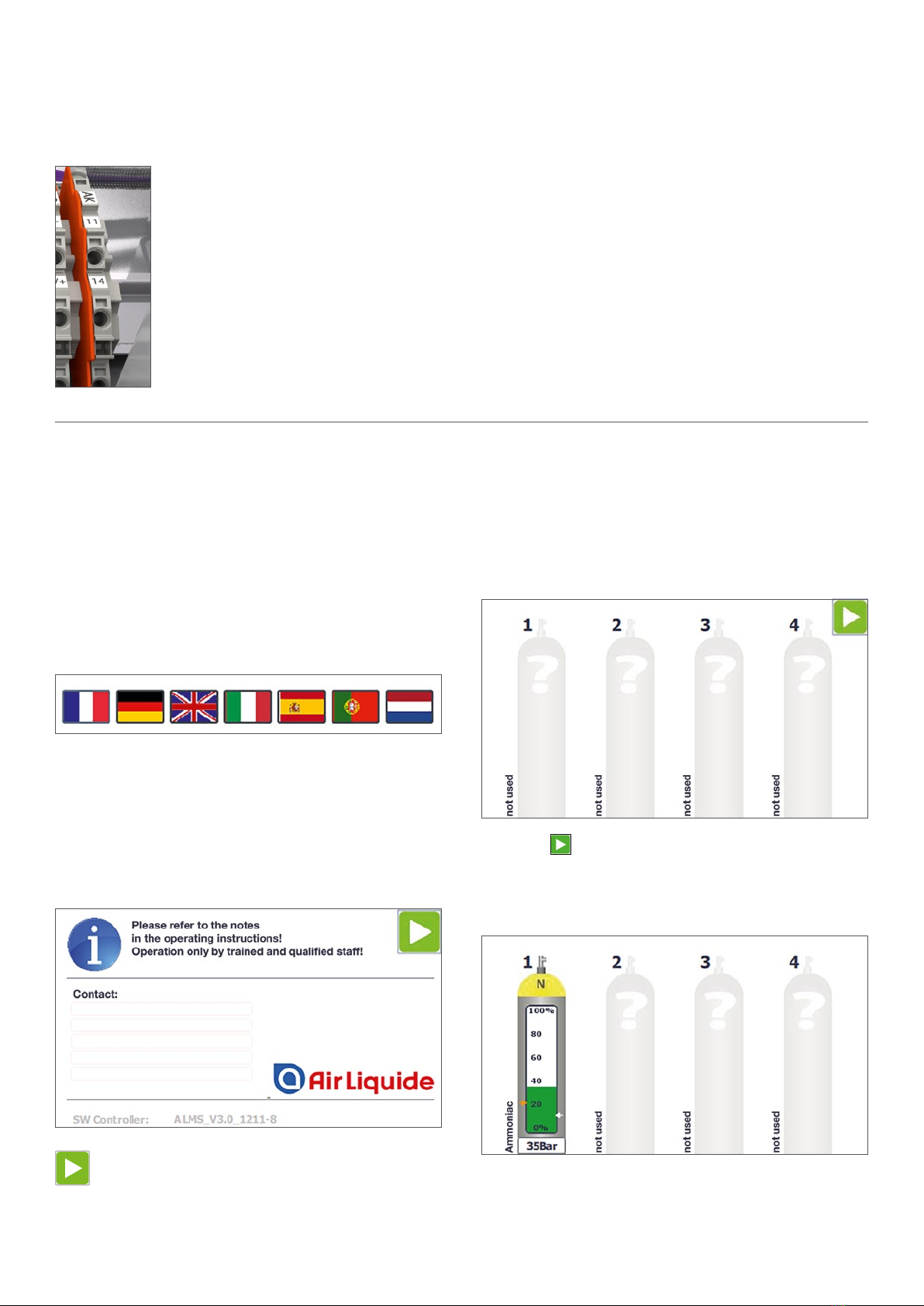
This guide will give you all the necessary information for op-
erating and installing an Air Liquide Monitoring System
ALMS. In this notice, the monitoring system is called the
ALMS.
3.1 Guidelines and general information
• ALMS complies to EU directives and standards for electri-
cal safety and electromagnetic compatibility. Improper use
can result in damage to persons and objects. Improper use,
installation, or operation nullifies any guarantee.
• When used in installations and under environmental condi-
tions requiring higher safety standards, the requirements
and regulations of your country must be observed.
• Always keep the equipment and the ALMS freely accessi-
ble.
• Modifications to the equipment and the connection of ad-
ditional devices fall under the responsibility of the operator.
These steps must be checked and, if necessary, corrected
by the operator.
• Accessories and options are optimally adapted to the de-
vice. Therefore, do not use custom solutions. Any modifica-
tions to the device and connection of auxiliary devices is
the responsibility of the operator and must be checked by
the user.
• For storage and transport, the unit should not be exposed
to extreme temperatures, shock, or vibration.
• Notes and information on operating specifications can be
provided on request.
3 General information

5
4.1 User responsibilities
The user agrees to only allow people to work at the pressure
device, who
• have read and understood the safety chapter and the warn-
ings in this manual. These employees are trained and in-
structed to work at the relaxation stations.
• The responsibilities of personnel for mounting, installation,
and operation must be clearly defined.
• Trainees must work at the pressure device only under the
supervision of an experienced person.
• All safety instructions and warnings must be kept in legible
condition.
4.2 Personnel duties
All persons who are authorized to work at the pressure device
must observe the basic regulations on workplace safety and
accident prevention, and familiarize them-selves with the safe-
ty data for the type of gas used before starting work.
The ALMS must not be used in
explosion hazard zones.
The voltage value printed on the type plate
must be respected.
Open the device only when no power is sup-
plied to it.
The ALMS may only be connected by qualified
personnel with appropriate specialist knowl-
edge.
Check the electrical equipment for the equip-
ment regularly. Correct loose connections and
damaged cables immediately.
If work on parts supplied with power is neces-
sary, a second person must be present to turn
off the central power switch if necessary.
Only operate the ALMS if the housing including
all connections are undamaged. Turn of pow-
er to a damaged instrument immediately.
Lay out cable that it does not present a trip
hazard.
Clean using a slightly damp cloth with soap
solution.
5 Identification
5.1 Name plate
On the right side of the ALMS, you can find a type plate with
information about:
Manufacturer, type, serial number, power supply, temperature
range, IP protection, CE marking, and Ex marking (if the de-
vice has the appropriate equipment).
4 Safety instructions

6
6.2 Use in hazardous areas
The ALMS EX model series may only be con-
nected to the pressure sensors of the compa-
nies BD-Sensors and Siemens (others on re-
quest).
These notes indicate hazards which cause
with high probability injuries or even death if
they are not avoided..
The ALMS monitoring system may only be in-
stalled in non EX zone.
6.1 Function
The ALMS is a permanent, continuously operating control
unit for transmitter to monitor the contents of pressurized
containers. In conjunction with the pressure transmitters
mounted at the relaxation stations or cylinder scales with a
signal output of 4 - 20mA, up to 4 channels (optionally 8 chan-
nels) can be displayed. In addition, two preset thresholds
trigger alarms; crossing threshold 1 changes the color of the
channel concerned from green to yellow, threshold 2 chang-
es the color from yellow red to with additional flashing. Also
at threshold 2, an acoustic signal is sounded by the built-in
horn.
Alarm output for use as a connection to further signaling
systems such as sirens, flash lamps, or alarm messages to
upstream systems.
Contact indicates a violation of the alarm limits or a broken
cable in the sensors.
Floating switchover contact: Contact load
max. 240V / 2A.
6 Use

7
D
E
C
5,20
8
F
Netzwerk
Alarmkontakt
Spannungsversorgung
Sensoren
8 7
A
B
23456 1
578 246 13
E
D
C
F F
D
B
A
E
C
ALMS
Wandlaschen
ZN05000116.1
24.08.16
GEWICHT:
A3
BLATT 1 VON 2
MASSSTAB:1:2
ZEICHNUNGSNR.
BENENNUNG:
ÄNDERUNG
ZEICHNUNG NICHT SKALIEREN
WERKSTOFF:
DATUM
SIGNATUR
NAME
ENTGRATEN
UND SCHARFE
KANTEN
BRECHEN
OBERFLÄCHENGÜTE:
WENN NICHT ANDERS DEFINIERT:
BEMASSUNGEN SIND IN MILLIMETER
OBERFLÄCHENBESCHAFFENHEIT:
TOLERANZEN:
LINEAR:
WINKEL:
QUALITÄT
PRODUKTION
GENEHMIGT
GEPRÜFT
GEZEICHNET
INAKON GmbH
D-64683 Einhausen
Bürstädter Straße 6a
24.08.16
B
A
AA
6
3
9,50
5,20
A-A
8 7
A
B
23456 1
578 246 13
E
D
C
F F
D
B
A
E
C
Gehäusebefestigung ohne
Wandlaschen
ZN05000116.1
GEWICHT:
A3
BLATT 2 VON 2
MASSSTAB:1:2
ZEICHNUNGSNR.
BENENNUNG:
REVISION:
ZEICHNUNG NICHT SKALIEREN
WERKSTOFF:
DATUM
SIGNATUR
NAME
ENTGRATEN
UND SCHARFE
KANTEN
BRECHEN
OBERFLÄCHENGÜTE:
QUALITÄT
PRODUKTION
GENEHMIGT
GEPRÜFT
GEZEICHNET
INAKON GmbH
D-64683 Einhausen
Bürstädter Straße 6a
Schutzvermerk
DIN ISO 16016 beachten
B
A
AA
6
3
9,50
5,20
A-A
8 7
A
B
23456 1
578 246 13
E
D
C
F F
D
B
A
E
C
Gehäusebefestigung ohne
Wandlaschen
ZN05000116.1
GEWICHT:
A3
BLATT 2 VON 2
MASSSTAB:1:2
ZEICHNUNGSNR.
BENENNUNG:
REVISION:
ZEICHNUNG NICHT SKALIEREN
WERKSTOFF:
DATUM
SIGNATUR
NAME
ENTGRATEN
UND SCHARFE
KANTEN
BRECHEN
OBERFLÄCHENGÜTE:
QUALITÄT
PRODUKTION
GENEHMIGT
GEPRÜFT
GEZEICHNET
INAKON GmbH
D-64683 Einhausen
Bürstädter Straße 6a
Schutzvermerk
DIN ISO 16016 beachten
D
E
C
5,20
8
F
Netzwerk
Alarmkontakt
Spannungsversorgung
Sensoren
8 7
A
B
23456 1
578 246 13
E
D
C
F F
D
B
A
E
C
ALMS
Wandlaschen
ZN05000116.1
24.08.16
GEWICHT:
A3
BLATT 1 VON 2
MASSSTAB:1:2
ZEICHNUNGSNR.
BENENNUNG:
ÄNDERUNG
ZEICHNUNG NICHT SKALIEREN
WERKSTOFF:
DATUM
SIGNATUR
NAME
ENTGRATEN
UND SCHARFE
KANTEN
BRECHEN
OBERFLÄCHENGÜTE:
WENN NICHT ANDERS DEFINIERT:
BEMASSUNGEN SIND IN MILLIMETER
OBERFLÄCHENBESCHAFFENHEIT:
TOLERANZEN:
LINEAR:
WINKEL:
QUALITÄT
PRODUKTION
GENEHMIGT
GEPRÜFT
GEZEICHNET
INAKON GmbH
D-64683 Einhausen
Bürstädter Straße 6a
24.08.16
Sensors
Network
Power supply
Alarm contact
When mounting the device, locations with the following neg-
ative conditions should be avoided:
• Heat (heater or direct sunlight)
7.1 General
Check equipment immediately after unpacking for any visible
damage. If damage is evident, please contact the distributor.
Delivery includes:
• ALMS monitoring system
• 4 x wall mount
• Instructions
7.2 Wall mounting
7.2.1 Wall mounting without bracket
7.2.2 Wall mounting with bracket
7 Installation
Device type A B
BCD 250 210 215
BCD 310 265 275
BCD 400 320 355
Device type C D E F
BCD 250 251 236 222 152
BCD 310 306 291 282 152
BCD 400 361 346 362 164

8
7.3 Create mains connection
Connection of the mains
power supply is made to
the designated terminals.
The printed voltage rating (see type label) must
match with the local voltage.
The mains connection may only be conducted
by qualified personnel with the appropriate
specialist knowledge.
The protective conductor must never be inter-
rupted. It is important to ensure that only
standard cable can be used with the protective
conductor.
7.4 Sensor connections for non Ex models
Connection of the pressure transducer takes place directly
at plug-in terminals that are identified corresponding to the
gas bottles.
S1 – S… (Different amount of sensors).
When connecting, switch off (disconnect power
supply).
For electrical connections, use shielded cable with a conduc-
tor cross section of 0.5 mm² to 2.5 mm².
Pin assignment: V+ Sensor +, V- sensor -, screen
The pressure transmitter may only be con-
nected by qualified personnel appropriate spe-
cialist knowledge. Installation instructions for
the pressure transmitter must be adhered to.
7.5 Sensor connection for Ex models
The monitoring system ALMS may only be in-
stalled in non-explosion hazard area!
The pressure transmitters are connected di-
rectly to the Zener barriers. The connections
are marked with sensor (S1 – S...) and corre-
spond to the gas cylinders (1 – x).
To comply with ATEX
standards and thus to
observe safety require-
ments, it is imperative
that the cable feeds
from the hazardous
area are laid out
through the provided
blue cable feed-
throughs. For devices
which additionally of-
fer the possibility of
cable leads from the
non-hazardous area
with gray cable feed-
throughs, only these
feedthroughs may be used. The installed plate for the Zener
barriers are to be considered a separation point.
The pressure transmitter may be connected
only by qualified personnel with the appropri-
ate specialist knowledge. The installation in-
structions of the pressure transmitter must be
adhered to.
If you use electrical equipment in installations and under en-
vironmental conditions requiring higher safety
standards, this should observe applicable laws and regula-
tions.
When connecting, shut down power
(disconnect power supply).
The approved maximum cable length
is 410 m. The cable cross-section
must not be lower than 0.5 mm2.
Connection:
Mishandling (improper connection
and installation) will invalidate the Ex
approval and any guarantees.
seperating plate

9
7.6 Alarm contact output
Alarm output for use as a connection to
further signaling systems such as sirens,
flash lamps, or alarm messages to up-
stream systems.
Contact indicates a violation of the alarm
limits or a broken cable in the sensors.
Floating switchover contact:
Contact load max. 230 V / 3 A AC;
24 V / 1 A DC
8.1 Language choice and
contact information
8.1.1 Start screen
After switching on or connecting supply voltage, the device
boots up. As soon as the start screen is displayed, the boot
process is complete. The unit is now ready for operation
Clicking on a country‘s flag sets the language accordingly,
and changes to the info screen.
8.1.2 Info image
Below „Contact:“, 5 lines can be used to enter e.g. contact
information for service. The lines can be edited by all opera-
tors. By default these lines are empty.
The software version is displayed at the bottom of the screen.
Clicking the arrow at the top right, will change the
screen and the main screen appear, in which the cyl-
inders 1...4 are displayed.
8.2 Main screen
8.2.1 The first 4 cylinders are displayed.
If the icon is displayed here, the device version can sup-
port more than 4 cylinders. When clicking the green arrow
the screen changes, and showing the cylinders 5…8.
8.2.2 Cylinder display for the connected sensor, (here S1).
8 Putting into operation

10
8.2.3 Warning and alarm limits
8.2.4 The absolute tank pressure is displayed at the bottom
of the bottle.
8.2.5 The name of the gas is displayed on the left, and free
text information is displayed to the right of the bottle.
8.3 Enter basic values
8.3.1 Clicking on the desired cylinder in the main menu will
lead you to the “Parameter screen”, where the neces-
sary basic settings can be entered.
8.3.2 An input or change to the basic values is only possible
with password entry. In the basic version, the default
value is “0000“ (for changing the password, see chap-
ter 11.5). and confirmation can be made with the OK
button. The user is automatically logged out after 15
minutes of inactivity.
Left arrow displays
warning limits.
F1 F2 F3 F4
TOUCH
SIMATIC HMI
Acetylene
18Bar
Primary cylinder
Not used
100%
80
60
40
20
0%
12
Right arrow displays
alarm limits.
F1 F2 F3 F4
TOUCH
SIMATIC HMI
Acetylene
18Bar
Primary cylinder
Not used
100%
80
60
40
20
0%
12
F1 F2 F3 F4
TOUCH
SIMATIC HMI
Acetylene
18Bar
Primary cylinder
Not used
100%
80
60
40
20
0%
12
F1 F2 F3 F4
TOUCH
SIMATIC HMI
Acetylene
18Bar
Primary cylinder
Not used
100%
80
60
40
20
0%
12
8.3.3 The alphanumeric keypad appears when entering text.
Key “123“ or „ABC“ switches between the number view
and symbol view
8.3.4 After entering the correct password, all basic values are
adjustable.
8.4 Select the Gas type
8.4.1 After entering the correct password, all basic values are
adjustable. Selecting the “Gas type“ is possible via a drop-
down menu. Scrolling up or down through the list or using
the right scroll bar with your finger allows you to search
the desired type of gas, selecting is done by clicking. A
commercially available stylus can facilitate this operation.
F1 F2 F3 F4
TOUCH
SIMATIC HMI
primary cylinder
F1 F2 F3 F4
TOUCH
SIMATIC HMI
primary cylinder

11
8.4.2 If the term “not used” is entered under
„Gas type“ this channel is considered
unused. No further values can be en-
tered, and the bottle appears gray in
the display. In this case, “not used” is
displayed as the gas type.
8.5 Additional information
In the line “Additional info” you can enter any free text with
the alphanumeric keyboard. This text is displayed vertically
to the right of the cylinder (“Primary cylinder”).
8.6 Cylinder size
In the dropdown menu “Size” the number of liters of the con-
nected bottle is entered (i. e. 50 l. This is important for calcula-
tions by the consumption monitor for compressed gases).
The geometrical volume of the connected vessels can be
reequested at the gas manufacturer.
8.7 Cylinder pressure
“Btl. press.”: here, you can enter the actual filling pressure of
gas cylinders used by this channel (for example, 200 or
300 bar) (This is important for calculations by the consump-
tion meter for compressed gases). This is also the basis of
the scaling of “Warning” and “Alarm”. Input is possible with
the numeric keyboard, which will be displayed only when
only numbers should be entered into an input field.
F1 F2 F3 F4
TOUCH
SIMATIC HMI
N
18Bar
not used
42Bar 40Bar
100%
80
60
40
20
0%
100%
80
60
40
20
0%
100%
80
60
40
20
0%
1234
Oxygen
Hydrogen
Acetylene
primary cylinder
F1 F2 F3 F4
TOUCH
SIMATIC HMI
Max: 400.0
Min: 0.0
200.0
If the value entered in the field “Fl. pressure”
is higher than the value of the sensor type, the
input will not be accepted. The value can not
exceed the maximum pressure of the sensor.
8.8 Warnung and alarm
In the input fields “Warning“ and “Alarm“ enter the required
reporting limits for alarm thresholds 1 and 2. These are
shown as arrows on the bottle (see item 8.2.3). Percentages
refer to the value entered in the field of “Fl. pressure”.
8.9 Sensor type, consumption and test
The buttons “Sensor type“, “Consumption“ and “Test“ are
used to switch to the corresponding submenus (Consumption
and Test will be explained in chapter 10).
8.10 Sensor type
Activating the “Sensor type” button opens the “Sensor type”
window. Sensor type” window opens. In the field, enter the
max. pressure of the connected sensor. The value can be
found in the data sheet or on the type plate of the sensor, e.g.
“400 bar”.
Exit with arrow button.

12
8.11 Installation Step by Step
8.11.1 Mount ALMS and install cables. Wiring according to
the connection diagram in the appendix.
Cable:
Non Ex: • min. 2 x 0.5 mm2 per sensorr
• Shielded cable e. g. LiYCY
• Cable length max. 410 m,
higher lengths possible
• Bundling of sensor connection cables in
one cable are allowed. Per sensor 2 cores.
• Do not lay live lines under current in the
cable in the cable or parallel to it.
Ex: • min. 2 x 0.5 mm2 LiYCY per sensor
• Permissible up to 410 m
• One cable for each sensor
• Bundling of sensor cables in one cables
are not allowed. Each sensor must be
connected with one cable.
• Cable identification blue
• Only route through blue cable gland
• Connect directly to Zener barrier
Pay attention to polarity!
8.11.2 Supply the ALMS with voltage and wait until the the
device responds with the language selection.
Select the language and continue with the green ar-
row key to the info screen.
Info: In the bottom line of the info screen the version no.
is displayed.
Continue to the main menue with the green arrow key.
In the delivery state, no sensor inputs are configured (gray
display).
The connected sensors must now be configured.
8.11.3 Select the cylinder via the touchpad which that
needs to be set. The window „Port Configuration“
opens.
The first time an input field is tapped the pass-
word 0000 needs to be entered. All entries can
be changed at any time.
Type of gas
After tapping, a selection field of all possible gas types that
are shown. Use your finger or the stylus to select and confirm
the gas type. The designation is displayed in the main menu
on the left, vertically next to the gas cylinder and the gas
cylinder changes to the color code of the gas type.
Additional information
This text is displayed vertically, to the right of the cylinder
e. g. “right cylinder”.
Sensor type
In the Type field, enter the max. pressure of the connected
sensor. The value can be found in the data sheet or on the
type plate of the sensor, e.g. “400 Bar”.
Size
Enter nominal capacity of connected cylinder. E.g. 50 l for a
single cylinder or 600 l for a bundle.

13
Cyl. pressure
Enter the pressure of the cylinder or bundle as specified by
Air Liquide.
Example: Enter “300 bar”, then the max. bottle content is cal-
culated to 300 bar. The pressure inside the bottle is set to
300 bar for 100 % and is displayed according to the cylinder
content. In the field below the cylinder, the current absolute
pressure is displayed.
Warning
When the warning limit is reached, the cylinder content are
highlighted in yellow.
Alarm
When the alarm limit is reached, the cylinder content is
marked in red color. An audible signal is emitted, the AK con-
tact is set and a message “Acknowledge horn” appears on
the screen.
By pressing the button next to the signal transmitter, or the
“Acknowledge horn” field, the alarm signal is canceled. The
alarm contact AK remains set until the cylinder pressure cyl-
inder pressure rises above the alarm limit again.
All necessary parameters for this connection are now already
entered. After exiting with the green arrow key the main
screen immediately shows continuously the pressure on the
main menu and monitoring is started. The above settings
must be be entered for all connected ports and remain stored
in a fail-safe manner until changing the values.

14
9.1 Level indicator and alarm
9.1.1 The level of the bottle will be dis-
played as an actual pressure value
(in bar) at the bottom of the bottle
symbol.
In addition, the colored bar indicates the percentage content
of the gas cylinder; in the normal state, the bar color is green.
9.1.2 If the level indication falls below the
set warning value, the color changes
from green to yellow.
9.1.3 If the level falls below the set alarm
value, the color changes from yellow
to red and flashes. In addition, the
built-in horn emits an acoustic sig-
nal.
F1 F2 F3 F4
TOUCH
SIMATIC HMI
N
18Bar
not used
42Bar 40Bar
100%
80
60
40
20
0%
100%
80
60
40
20
0%
100%
80
60
40
20
0%
1234
Oxygen
Hydrogen
Acetylene
primary cylinder
F1 F2 F3 F4
TOUCH
SIMATIC HMI
N
18Bar
not used
42Bar
40Bar
100%
80
60
40
20
0%
100%
80
60
40
20
0%
100%
80
60
40
20
0%
1234
Oxygen
Hydrogen
Acetylene
primary cylinder
F1 F2 F3 F4
TOUCH
SIMATIC HMI
N
18Bar
not used
42Bar
40Bar
100%
80
60
40
20
0%
100%
80
60
40
20
0%
100%
80
60
40
20
0%
1234
Oxygen
Hydrogen
Acetylene
primary cylinder
9.2 Bottle change – Alarm clearing
9.2.1 After falling below the set alarm value, the display will
show the display “deactivate horn“. In addition, the sig-
nal transmitter is activated and the Alarm contact AK
is closed.
By clicking on “Acknowledge horn”, the horn contact is switched
off again and the message disappears.
Alternatively, the horn can be acknowledged via the button
mounted on the right side.
The alarm contact remains activated as long as a cylinder
filling level is the alarm limit or an unrectified fault is present.
The red flashing bar in the cylinder also remains on the dis-
play until the gas shortage is eliminated.
After a new cylinder has been connected, the color bar first
changes to yellow and then to green. When the pressure com-
pensation has taken place, over 80 % of the filling quantity
and 2 minutes have elapsed, the alarm control is restarted.
9 Operation

15
9.3 Alarm indicator / Alarm window
9.3.1 If a problem is present in the device, a message window
opens in the foreground with a corresponding message
indicator. Below are the number of active errors and the
message status.
9.3.2 Message status:
1. Warning triangle flashes white/yellow: unacknowl-
edged error.
2. Warning triangle white: error has been acknowl-
edged, but has not yet been fixed.
9.3.3 Clicking on the warning symbol opens the message
window.
F1 F2 F3 F4
TOUCH
SIMATIC HMI
N
Acetylen
18Bar
primaere Flasche
Sauerstoff
Wasserstoff
42Bar 40Bar
100%
80
60
40
20
0%
Acetylen
18Bar
100%
80
60
40
20
0%
100%
80
60
40
20
0%
100%
80
60
40
20
0%
1234
F1 F2 F3 F4
TOUCH
SIMATIC HMI
N
Acetylen
18Bar
primaere Flasche
Sauerstoff
Wasserstoff
42Bar 40Bar
100%
80
60
40
20
0%
Acetylen
18Bar
100%
80
60
40
20
0%
100%
80
60
40
20
0%
100%
80
60
40
20
0%
1234
9.3.4 Errors are displayed in the message window.
• Red: Error not repaired. Unacknowledged
• White: Error not repaired. Acknowledged
• Bright Red: Repaired error. Unacknowledged
• Blue: Selected message
9.3.5
F1 F2 F3 F4
TOUCH
SIMATIC HMI
Flasche 1: Stoerung Druckfuehler!
Flasche 3: Stoerung Druckfuehler!
Flasche 5: Stoerung Druckfuehler!
Flasche 7: Stoerung Druckfuehler!
Keine / schlechte Mobilfunkverbindung !
Meldungen - Behobene Stoerungen quittieren !
All occurring errors must be acknowledged.
For this, click message and acknowledge
with button.
9.3.6 Fixed and acknowledged errors disappear from the list.
9.3.7
F1 F2 F3 F4
TOUCH
SIMATIC HMI
Flasche 1: Stoerung Druckfuehler!
Flasche 3: Stoerung Druckfuehler!
Flasche 5: Stoerung Druckfuehler!
Flasche 7: Stoerung Druckfuehler!
Keine / schlechte Mobilfunkverbindung !
Meldungen - Behobene Stoerungen quittieren !
By clicking the message indicator again or
clicking the close button, the alarm window
can be closed again.
9.4 Taking out of operation
Take out of operation by breaking the main power supply. The
Instructions of the connected transducer must be observed.

16
10.1 Consumption Measurement
Clicking the button “Consumption“ takes you to the corre-
sponding submenu.
If the selected channel has not been set as compressed gas
previously, a window appears with the message “Consumption
counter only for pressure gaz available!“.
If a compressed gas was entered, the window below appears.
“Since connection“ is automatically reset when a new bottle
is connected. Reconnection of a new gas cylinder is detected
when bottle filling and pressure is greater than the set warn-
ing limit for 2 minutes.
F1 F2 F3 F4
TOUCH
SIMATIC HMI
N
1Bar
100%
80
60
40
20
0%
1
Consumption meters
only available for compressed gases!
Consumption
!"#$%&'()"#*&+(+,$*"#-.*/0/)-/1-+*2",*3"&',+$$+4*5/$+$
6
*
*
“Today“ is always reset at 00:00:00 AM.
All three “Consumption“ meters are free counters that can be
reset at any time. It also displays when the consumption
counter was activated.
Resetting the display “Today“ and „Consumption“ meter is
done with the button “enable reset“. When clicking this but-
ton, individual reset buttons are displayed for a few seconds
in the image, which enable manual reset by further clicking.
Back to the origin menu.
10.2 Pressure test
10.2.1 Pressing the button “Test“ opens the submenu.
10.2.2 First, a time must be entered in the box “Set test dura-
tion.“ By clicking the button “Start Test“ the test is
activated.
10 Additional functions

17
The fields shown in the window have the following meaning:
Current pressure
displays the current tank pressure.
Start pressure
is the pressure at which the test was started.
Remaining time
indicates the remaining duration of the test.
Pressure Change
is the difference in current actual pressure – starting pres-
sure. Once the test is over, the last difference remains here.
The test can be restarted during the test run with “Test Start“.
F1 F2 F3 F4
TOUCH
SIMATIC HMI
Test – Start
Test
Pressure hold test
Enter test duration:
Actual pressure:
Starting pressure:
Remaining time:
Pressure change:
Test is running...
10 min
194.87 Bar
196.21 Bar
9,2 min
-1.34 Bar
1.
2.
3.
N
194Bar
100%
80
60
40
20
0%

18
11.1 Language
Press the F1 key to go from any screen in the device
Settings / Basic settings window.
The language can be set here by clicking the appropriate flag.
In addition, dimming the backlight is also possible.
11.2 Info
F1 F2 F3 F4
TOUCH
SIMATIC HMI
Geraetesetup / Grundeinstellungen
Sprache
Display Helligkeit
125
PROFIBUS Adresse
Passwort
1
25
ok
GPRSUhrzeit
20% 40% 60% 80% 100%
Clicking on “i“ opens the info screen, which is dis-
played also when the device is started (see item
8.1.2 too).
11.3 Time
11.3.1 By pressing the button “Time“ you can open the
“Settings / Clock“ window.
11.3.2 The system time can be set here. To do this, enter the
date and time in the field “New time“ in the specified
format, and then apply by pressing “Set“.
11.3.3 The current time is displayed in the field above. The
time is used to store the reset time-point of consump-
tion meters.
11.4 Password
11.4.1 Using the button “Password“ you can open the image
screen for changing the password. Here, you can
change the user password, which is “0000“ by default.
11.4.2 If the user is not yet registered, an image appears
above. You must first enter the current password by
clicking on “Login- / out“ so that it can subsequently
be changed. Enter password (keyboard window) and
click OK to confirm.
11.4.3 If the password is correct, the image “Change user-
password“ appears. In the field “New Password“ you
can now enter the new password.
F1 F2 F3 F4
TOUCH
SIMATIC HMI
Login / Logout
Change user password
Setup / Password
User must log in first!
F1 F2 F3 F4
TOUCH
SIMATIC HMI
User must log in first!
Setup / Password
OKCancel
Password:
Login / Logout
Login
11 Device setup / basic settings

19
11.4.4 After clicking on the blue input box, another window
opens, here, the same password must be entered
twice and confirmed with OK. The password is
changed immediately. Test the change using the log-
on / logoff button.
11.4.5 If the user‘s password is lost, you can log in temporar-
ily with “9999“ onto the device and then enter a new
user password as described as above.
F1 F2 F3 F4
TOUCH
SIMATIC HMI
Change user password
Setup / Password
New password:
Login / Logout
F1 F2 F3 F4
TOUCH
SIMATIC HMI
New password
OKCancel
Login
New password:
Confirm:
Login / Logout
Setup / Password
11.5 Set alarm volume
The volume can be adjusted by tapping the Volume Low or
High Up keys. When exiting, the setting is saved in a fail-safe
manner.
Do not clean the ALMS using solvents or harsh
cleaning products.
Clean only using a cloth gently dampened with
soapy water.
Do not dispose of the device or its accessories via
household refuse. Take to a recycling station for
electronic or electrical waste.
12 Care and Maintenance 13 Disposal

20
Technical documents on request
14 Technical Data
Line voltage 85 to 264 V AC, 47 to 63 Hz
Performance recording 180 mA at 120 V AC
90 mA at 240 V Ac
Operating environment temperature -10 °C to 60 °C
Protection type IP65
Measurements for plastic wall housing
Typ 250
Typ 310
Typ 400
264 x 234 x 144 mm (height x width x depth)
324 x 289 x 145 mm (height x width x depth)
344 x 404 x 161 mm (height x width x depth)
Weight / Basic enclosure with maximum
configuration
Typ 250
Typ 310
Typ 400
3.2 kg (non-Ex-models) to 3.6 kg (Ex-models)
5.6 kg (non-Ex-models) to 6.0 kg (Ex-models)
from 8.2 kg
Number of sensors
Typ 250
Typ 310
Typ 400
4 (max. 8) non-Ex models, 2 (max. 8) Ex-models
4 (max. 8) non-Ex models, 2 (max. 8) Ex models
4 (max. 32) non-Ex models, 2 (max. 32) Ex models
Voltage supply for measurement instrument 24 V DC
Sensor signal input 4 – 20 mA
Display accuracy Depends on sensor
Alarm contact
Voltage-free changeover contact
at a maximum contact load of 230 V / A AC;
24 V / 1 A DC
Housing material ABS RAL7035
Transparent lid frame Polycarbonate RAL7024
Signal generator 90 dB
Applied norms
Electromagnetic tolerance Guideline 2014 / 30 / EU EN
Low voltage guidelines Guideline 2014 / 35 / EU
Explosion hazard zones
Guideline 2014 / 35 / EU
EN 60079-0
EN 60079-15
EX classification for use of sensor in EX zones II (1) G [Ex ia Ga] IIC X
Allowed pressure transducer EX Model BDS 17.600 Ex
Further upon request
This manual suits for next models
33
Table of contents
Other Air Liquide Measuring Instrument manuals
Popular Measuring Instrument manuals by other brands

Dwyer Instruments
Dwyer Instruments TUF series Specifications-installation and operating instructions

Jaquet
Jaquet T411 operating instructions

Tenma
Tenma TEN01073 quick start guide

T&D
T&D TR7 Series quick start guide

DeFelsko
DeFelsko PosiTector 6000 quick guide

LogTag Recorders
LogTag Recorders USRIC-4 Software Download and Quick Start Guide