Instructions for use SS 20.515 Page 5
Assembly
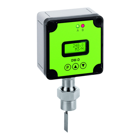
For the assembly of the SCHMIDT®Flow sensor SS 20.515, five differ-
ent assembly versions optimized for use in cleanrooms are available, in
order to cover all the different applications (see Table 1).
First, the required holes, depending on the assembly version, must be
drilled, and the corresponding fixing socket must be mounted in that
hole. Then the connecting cable is introduced with its open into the fixing
socket from the cleanroom side until the cable bushing protrudes from
the fixture by only about 5 cm. Please note that after assembling the
sensor, there must still be room for this protruding cable length in the
void behind the assembly bushing. Now connect the sensor to the con-
necting cable (plug in and screw down spigot nut), insert it into the fixture
bushing and tighten the holding fixture screw by hand. Now the sensor
can still be aligned accurately by hand, if required. Finally, the holding
fixture screw must be tightened with a key wrench (wrench size 22) until
the sensor is sufficiently secured against twisting.
Prior to commissioning the sensor, remove the protective cap.
Assembly in the ceiling
The angled sensor is designed for assembly below the ceiling.
After the sensor has been inserted into the fixture bushing and the as-
sembly screw tightened (first only by hand), the sensor head will auto-
matically have an optimum position for the detection of the vertical
downdraft flow from the ceiling. Only the torsional angle of the sensor
arm in parallel to the ceiling must still be aligned. Then tighten the as-
sembly screw using the fork wrench (hold sensor, if necessary) until the
sensor is secured against twisting.
Assembly in the wall
The straight sensor is designed for assembly on a wall.
Insert sensor into the fixture bushing and thoroughly tighten the assem-
bly screw. No alignment to the flow is required, due to the omnidirection-
al measurement characteristic of the sensor head.
