AIR SYSTEMS BB15-CO User manual

Manual No. BREBX013
(Rev. 8 Sept. 2012)
OPERATING MANUAL
MODELS:
BB15-CO
BB30-CO
BB50-CO
BB75-CO
BB100-CO
BB150-CO
AIR SYSTEMS INTERNATIONAL, INC.
829 Juniper Crescent, Chesapeake, Va 23320
Telephone (757) 424-3967
Toll Free 1-800-866-8100
Fax No. (757) 424-5348
hp://www.airsystems.com
e-mail: sales@airsystems.com
French Canadian and Spanish versions of this manual are available online at www.airsystems.com

BB15 Series BB30 Series BB50 Series BB75 Series BB100 series BB150 series
Size 19”L X 13”H X 7”D 19”L X 13”H X 7”D 24”L X 17”H X 8.5”D 24”L X 17”H X 8.5”D 26.5”L X 21”H X 9”D 26.5”L X 21”H X 9”D
Weight 12.3 lbs/5.6 kg 19.7 lbs/8.9 kg 26.4 lbs/12 kg 34.2 lbs/15.5 kg 38.8 lbs/17.6 kg 38.8 lbs/17.6 kg
Inlet Size 1/4” industrial
interchange
1/2” industrial
interchange
1/2” industrial
interchange
1/2” industrial
interchange
1/2” industrial
interchange 1” Chicago
No. of Outlets 1 2 standard
3 op onal 46 or single 1/2”
NPT outlet
4-8 or single
1/2” NPT outlet
(3) 1/2” industrial
interchange
Maximum Air
Flow (cfm/bar)
15 scfm @ 110 psi
425 lpm @ 7.6 bar
30 scfm @ 110 psi
850 lpm @ 7.6 bar
50 scfm @ 110 psi
1415 lpm @ 7.6 bar
75 scfm @ 110 psi
2124 lpm @ 7.6 bar
100 scfm @110 psi
2832 lpm @7.6 bar
150 scfm @110 psi
4248 lpm @7.6 bar
Remote
Alarm Signal No Yes Yes Yes Yes Yes
Maximum Inlet
Pressure 150 psi (10.3 bar)
Relief Valve 125 psi (8.6 bar)
Monitoring Inline Con nuous Monitoring of Carbon Monoxide (CO)
Power 9-16 VDC or 115 VAC 50/60 Hz
SPECIFICATIONS
Item # Descripon BB15 BB30 BB50 BB75 BB100 BB150
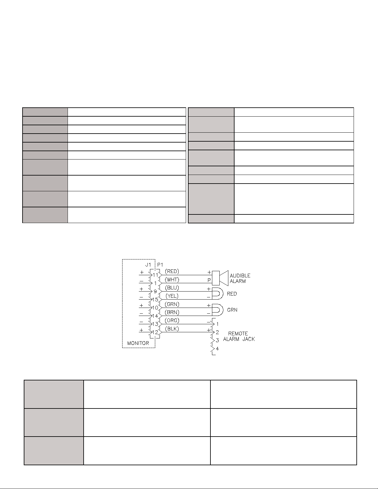
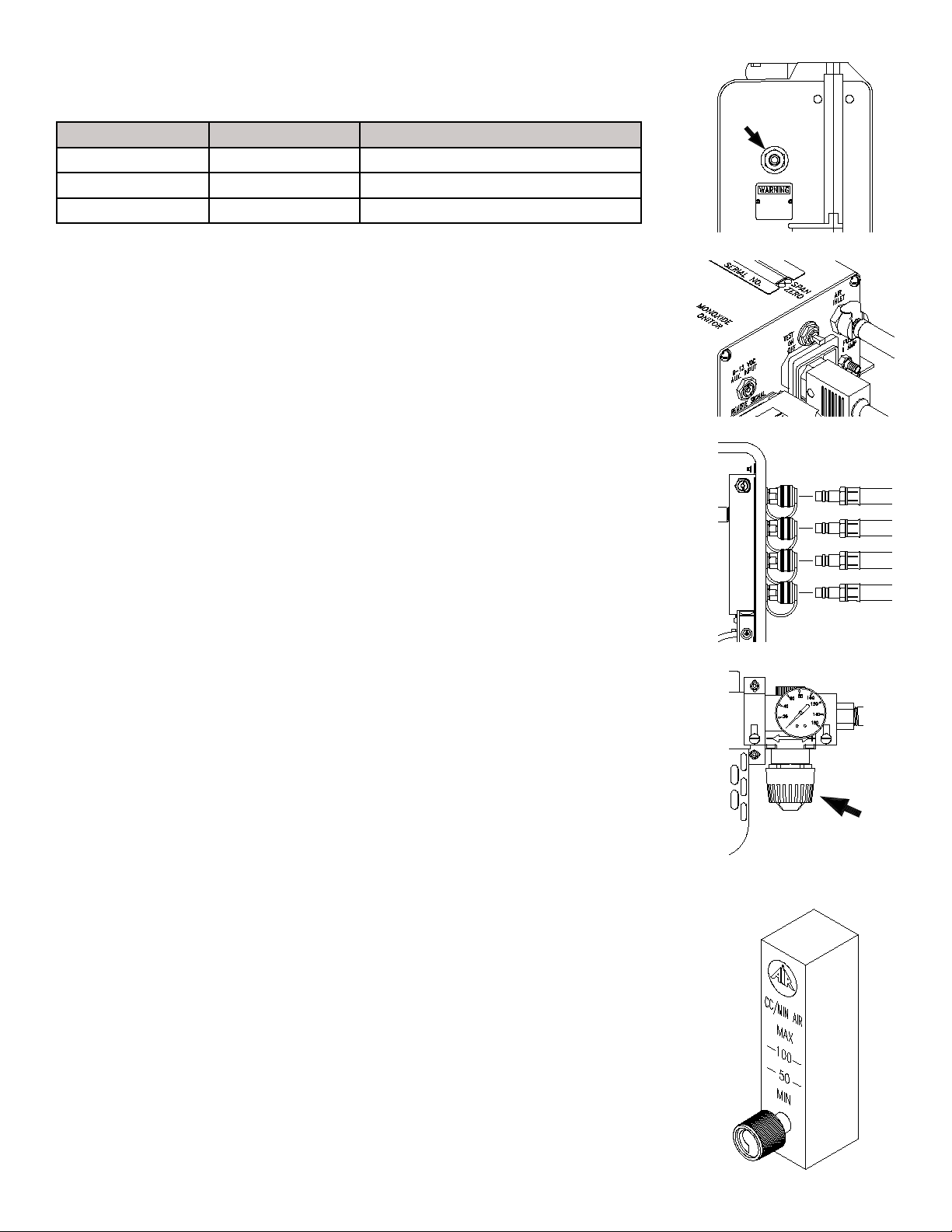
1Remote Alarm Jack N/A ELJP004 ELJP004 ELJP004 ELJP004 ELJP004
2Remote Alarm Jack Cover N/A ELJP005 ELJP005 ELJP005 ELJP005 ELJP005
3High CO Audible Alarm N/A ELLS004 ELLS004 ELLS004 ELLS004 ELLS004
4 High CO Indicator N/A MONC004 MONC004 MONC004 MONC004 MONC004
5 Clear LED Lens N/A ELDS013 ELDS013 ELDS013 ELDS013 ELDS013
6Normal Operaon Indicator N/A MONC005 MONC005 MONC005 MONC005 MONC005
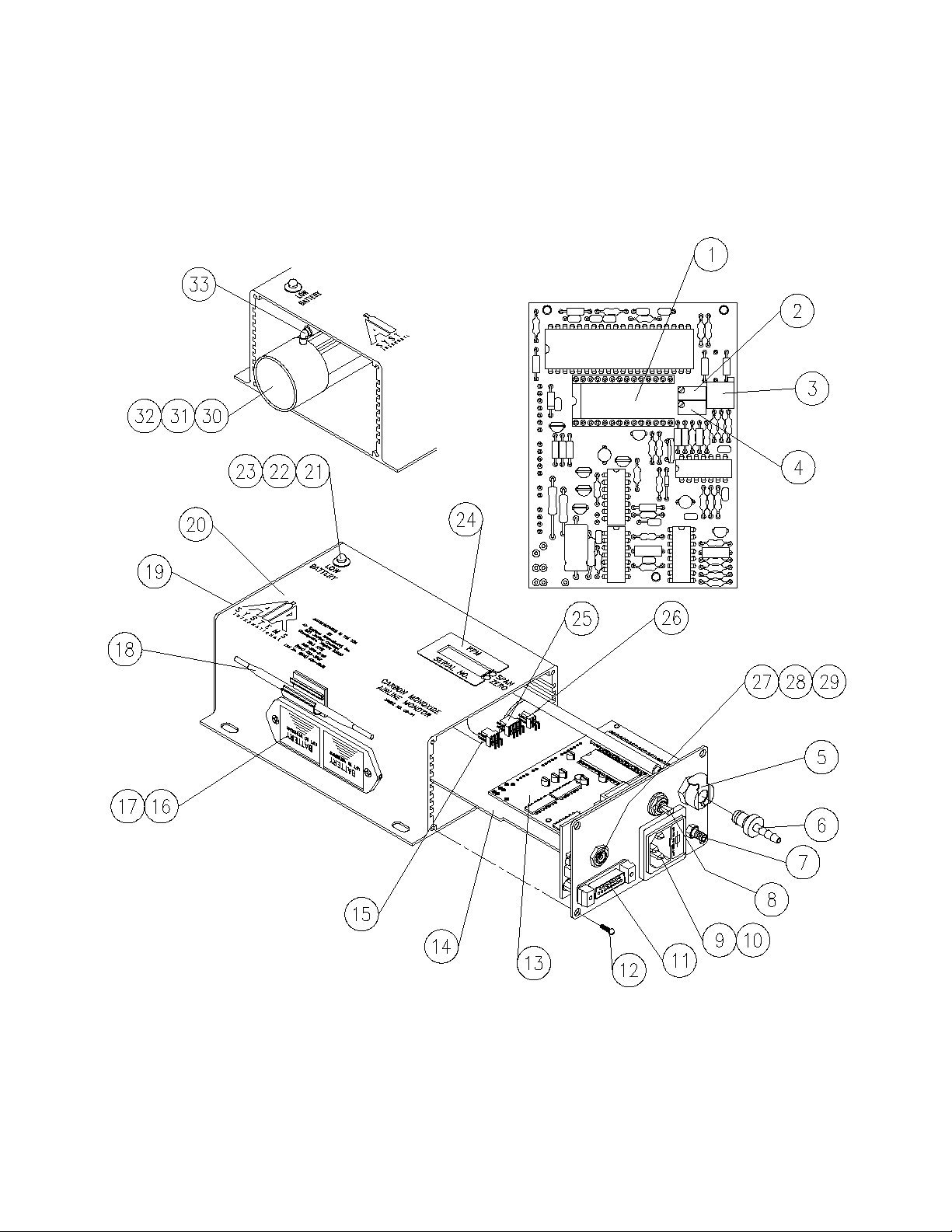
7Inlet Fing QDH3PL6M QDH5PL8M QDH5PL8M QDH5PL8M QDH5PL8M QDCHI16M
8 Pressure Gauge GA20160B GA20160B GA20160B GA20160B GA20160B N/A
9 Relief Valve VR4125BR VR4125BR VR4125BR VR4125BR VR4125BR VR4125BR
10 Hansen Coupling QDH3SL6M QDH3SL6M QDH3SL6M QDH3SL6M QDH3SL6M QDH5SL12M
10a Schrader Coupling QDSSL6M QDSSL6M QDSSL6M QDSSL6M QDSSL6M N/A
11 Hansen Dust Cap QDH3DCAP QDH3DCAP QDH3DCAP QDH3DCAP QDH3DCAP N/A
11a Schrader Dust Cap QDSDCAP QDSDCAP QDSDCAP QDSDCAP QDSDCAP N/A
12 1st Stage Filter Assembly 15FLTRAW WL251 WL007 WL175 WL066 WL132
13 2nd Stage Filter Assembly 15FLTRCW WL253 WL008 WL177 WL017 WL059S
14 3rd Stage Filter Assembly 15FLTRDW WL255 WL009 WL179 WL018 WL060S
15 Flowmeter WL033NS WL033NS WL033NS WL033NS WL033NS WL033NS
16 Pressure Regulator 15REGW WL257 WL015 WL181 WL015 WL013A
17 Carbon Monoxide Monitor CO-91AB CO-91 CO-91 CO-91 CO-91 CO-91
18 115 VAC Recessed Plug ELJP006 ELJP006 ELJP006 ELJP006 ELJP006 ELJP006
BREATHER BOX™ PARTS IDENTIFICATION
2

BREATHER BOX™ PARTS IDENTIFICATION
MODEL BB15-CO MODEL BB30-CO
MODELS BB50-100-CO MODEL BB150-CO
3

Breathing Air Quality Posi on Statement
The responsibility for the quality of breathing air rests with the user. Compliance with federal, state,
or local regula ons are the responsibility of the user and this recommenda on does not supersede any
exist-
ing rules, regula ons, or laws which may apply. Breathing air ltra on products
meet or exceed CGA Grade-D
speci ca ons for air quality as adopted by Federal
OSHA. Compressor air quality standards meet or exceed
OSHA 1910.134 requirements. When the components are used in accordance with the manufacturer's instruc-
ons and recommenda ons, the "system" meets or exceeds federal regula ons presently in force. It is incum-
bent upon the user to comply with any changes in the regula ons or law which may occur in future situa ons.
The air supply compressor should be located in a safe, clean ambient air environment. This "safe" loca-
on should be tested periodically using proper instruments to ensure clean ambient air quality on a consistent
basis. Total system Grade-D air quality should be tested at the me of ini al setup. If the compressor is moved,
retes ng air quality is recommended. Should the loca on or environment signi cantly change, the air quality
should be retested. The compressor lters and oil level should be checked daily and changed when contami-
nated or when the maximum number of "run" hours is achieved.
This series of air ltra on units should be used according to the recommenda ons speci ed in the
manual. The standard ltra on package is not explosion-proof and should be located in a non-explosive en-
vironment. (An intrinsically safe model is available, please contact the factory for informa on.) The carbon
monoxide monitor should be calibrated monthly or if the accuracy of the monitor is in ques on. System air
quality should be tested for, but not limited to, the following Grade-D air components:
CO - Carbon Monoxide
O2 - Oxygen
CO2 - Carbon Dioxide
H2O - Water (Moisture Content)
Hydrocarbons (Oil Mist)
Total Par culates
The maximum allowable level of these air quality components varies depending on
Grade-D or E requirements. Contact sales for a copy of the latest standards.
Our Breathing Air compressors and ltra on systems meet all of the following federal
speci ca ons when used and serviced in accordance with our instruc ons.
Federal OSHA 29 CFR 1910.134
"Compressor Opera ons for Breathing Air"
Army Corps of Engineers EM385-1-1,
paragraph 07b-11-4,
"Compressed Breathing Air"
4

CARBON MONOXIDE MONITOR OVERVIEW
The monitor will analyze the air sample and display the CO concentra on in parts per million (ppm). The
system’s green “NORMAL” opera on light will illuminate and the red “HIGH CO” light will icker approximately
every second when the CO level is below 10ppm (5ppm Canadian). If the CO concentra on level exceeds the
alarm set point, the green “NORMAL” light will turn o , the red “HIGH CO” light will illuminate, the audible
alarm will sound, and the remote alarm connec ons will energize. Once the CO concentra on levels drop be-
low the alarm set point, all alarm indicators will deac vate and the unit will return to “NORMAL” opera on.
1st Stage Par culate/Bulk Liquid Separa on
Auto drain and lter change indicator. Re-
moves 95% bulk par culate and liquids @ 5
microns.
2nd stage Oil Coalescing and Ultra Fine Par culate
Auto drain and lter change indicator. Re-
moves oil and par culate to 99.9998% @ 0.01
microns.
3rd Stage Ac vated Charcoal
Manual drain and lter change indicator. Re-
moves organic vapors, odors, and tastes. Less
than 0.003 pp/wt remaining oil content.
FILTRATION EFFICIENCY
Size 2.75”H X 6.57”L X 5.1”W
Weight 2.8 lBS. (1.27kg.)
Case Extruded Aluminum - anodized black
Voltage 115 VAC and/or 9-16 VDC
Shielding Internal RFI/EMI lters
Fuse 115 VAC/1 amp fast ac ng
Opera ng
Temperature
4° to 113° Fahrenheit
(-15.5° to 45° Celcius)
Humidity
Range 10% to 90% rela ve humidity
Flow
Requirement 50 - 100 cc/min
Display 3 digit LCD
CO concentra on
Test Circuit Manually ac vated
Sensor Type Sealed electrochemical sensor for
Carbon Monoxide
Accuracy +/-1% full scale
Response 90% in 10-15 seconds
Detectable
Range 0-200 ppm CO
Calibra on Manual CO zero and span adjustments
Alarm Se ng 10 ppm CO (5 ppm - Canadian)
Warning
Signals
Normal opera on - Green Light
High CO - Red Light
High CO - Audible Alarm
Low Ba ery - Amber Light
Warranty 2 years from original date of purchase
MONITOR SPECIFICATIONS
15 PIN CONNECTOR
WIRING DIAGRAM
5

CO MONITOR PARTS BREAKDOWN
6

ITEM # DESCRIPTION PART #
1LCD Display MONC703
2Span Potenometer MONC702A
3Alarm Set Point Potenometer MONC702A
4Zero Potenometer MONC702
5Air Sample Inlet Socket MONC001
6Air Sample Plug MONC002
7Air Exhaust Port MONC003
8On/O/Test Switch MONC007
9 Recessed Plug With Fuse Holder MONC020
10 1 Amp Fast Acng Fuse, 5 X 20Mm ELF001
11 15 Pin Socket MONC520
12 Faceplate/Endplate Screw MONC023
13 Main Circuit Board Assembly CO-91PCB
14 Power Supply Board CO-91PSB
15 Sensor Connector (Soldered To PCB) MONC509
16 Baery Box MONC006
17 9 Volt Baery ELB9V
18 Calibraon Tool MONC028
19 End Plate CO-91BEP
20 Aluminum Housing CO-91HOU
21 Led Socket MONC009LA
22 Yellow Led MONC008NS
23 Led Socket And Yellow Led CO-91LED
24 PPM/Serial No. Scker MONC031
25 Baery Box Connector (Soldered To PCB) MONC516
26 Led Connector (Soldered To PCB) MONC511
27 12 VDC Power Socket MONC522
28 12 Volt Power Plug (Oponal) ELJP018
29 12 Volt Cable (Order By The Foot) ELCB035
30 CO Sensor CO-91NS
31 CO Sensor Holder MONC810
32 CO Sensor Electrical Leads CO-91SL
33 90° Hose Barb MONC811
CO MONITOR PARTS BREAKDOWN
7

STEP 1)
Secure a primary air source of sucient air ow and discharge pres-
sure. The number and type of respirators being used determines the
ow rate and pressure required.
STEP 2)
Check airline monitor for fresh 9 volt baeries and turn unit on. Connect
the remote signal cable, 115 VAC plug, and air sample hose to the monitor.
Place the “ON/OFF/TEST” switch to the “ON” posion. Allow 30 seconds
for the readout to stabilize. If a reading other than “00” is displayed, cali-
braon of the monitor may be necessary. See calibraon procedure.
Note: Remote signal cable does not apply to BB15 series.
STEP 3)
Connect the extension cord to a 115 VAC receptacle.
Note: The CO monitor can run o the 9 volt baeries if AC power is not
available.
STEP 4)
Connect the oponal remote alarm (DC only) assembly to the remote
alarm jack.
Note: This step does not apply to BB15 series.
STEP 5)
Close the owmeter by turning the control knob fully clockwise. Do not
over-ghten.
BREATHER BOX™ SETUP AND OPERATION
Note: Always operate the Breather Box™ in the upright posi on. Failure to comply may result in one or all
of the following:
1) Auto drains will not func on properly. This may result in the contamina on of the CO monitor and cause
oil/water to be passed through respirator hose and into the worker’s mask.
2) Auto drains may become clogged.
3) Filters may accumulate moisture and/or contamina on.
8

MODEL # MIN. HOSE I.D. INLET FITING
BB15 SERIES 3/8” 1/4” INDUSTRIAL INTERCHANGE
BB30-100 SERIES 1/2” 1/2” INDUSTRIAL INTERCHANGE
BB150 SERIES 3/4” 1” CHICAGO FITTING
STEP 6)
Connect the air source, 150 psi max., to the inlet ng.
STEP 7)
Hold the “ON/OFF/TEST” switch in the “TEST” posion. All local and remote audi-
ble/visual indicators will acvate. If indicators do not acvate, check all electrical
connecons, then call factory repair dept.
Note: An alarm funcon test can be performed at any me by liing the “ON/
OFF/TEST” switch to the “TEST” posion.
STEP 8)
Aach desired respirators and hoses to the quick connect couplings.
Note: Some models may not have respirator connecons. They may be ordered
with NPT outlets for connecon to points of aachment.
STEP 9)
Adjust the outlet pressure to the seng recommended by the respirator man-
ufacturer. Turn the knob clockwise to increase pressure, counterclockwise to
decrease pressure.
STEP 10)
Adjust CO monitor air sample ow rate by turning the owmeter control knob coun-
terclockwise unl the ball hovers between 50 and 100 cc/min. The box is now ready
for operaon.
The monitor will analyze the air sample and display the CO concentraon in parts per
million (ppm). The system’s green “NORMAL” operaon light will illuminate, and the
red “HIGH CO” light will icker faintly approximately every second when the CO level is
below 10ppm (5ppm Canadian).
When the CO concentraon level exceeds the alarm set point, the green “NORMAL”
light will turn o, the red “HIGH CO” light illuminates, the audible alarm will sound,
and the remote alarm connecons will energize.
When CO concentraons drop below the alarm set point, all alarm indicators will deac-
vate and return to normal operaon.

SYSTEM MAINTENANCE
Filter Housing/Bowls: Periodic cleaning of the polycarbonate bowls may become necessary. Remove the auto
drains and clean the bowls with a mild soapy solu on. The auto drains may also be cleaned with a mild soapy
solu on at this me. Dry and reinstall into the lter housing.
Filter Change
: The ltra on system consists of lter change indicators which will gradually change from green to
orange when lter life is spent.
Note: Air must be owing through the lters before the lter change indicators will func on.
With system pressurized, close inlet ond outlet ball valves. Release the lter trio pressure by pressing the manual
drain assembly to the side. Remove the bowl assemblies by releasing the lock ring.
Calibra on: Monitor calibra on should be done monthly or whenever the reading may be ques onable. A cali-
bra on date s cker should be a xed for future reference. To obtain an accurate calibra on, we recommend the
use of Air Systems calibra on kits.
Part Number:
BBK-10 Canadian calibra on kit for CO monitor; 10ppm CO, zero air, regulator and case - 17 liter size.
BBK-20 Calibra on kit for CO monitor; 20ppm CO, zero air, regulator and case - 17 liter size.
BBK-20103 Calibra on kit for CO monitor; 20ppm CO, zero air, regulator and case - 103 liter size.
DECAL085 Calibra on decal, sold in sheet of 14.
To assure sensor accuracy, calibra on of monitor is required. If you cannot obtain an accurate calibra on, sensor
replacement may be necessary. Consult Repair Service Department before ordering.
Part Number:
CO-91NS Replacement CO sensor
CAUTION: Always depressurize the system before performing service.
1) Make sure all personnel have egressed from the work area.
2) Shut o air source to the box.
3) Remove air pressure from the box by pulling the relief valve ring out.
4) Turn the CO monitor o . Do not remove the 9 volt ba eries. These are used to maintain a
bias voltage to the sensor; this keeps the sensor ready for immediate use.
5) Disconnect airline hoses.
6) Install dust caps if applicable.
SHUTDOWN
These ba eries provide the required con nuous bias voltage to the CO sensor and power the monitor in the
event of AC power loss. If AC and DC power are removed for a period of 2 hours or more, a 1 hour restabiliza-
on period is required on the sensor as era c readings may occur.
Ba ery Replacement:
Replace 9 volt ba eries when the amber “Low Ba ery” light illuminates. If the monitor
is not used for 90 days, check the 9 volt ba eries and replace if necessary.
MONITOR BATTERY REPLACEMENT
10

SENSOR REPLACEMENT
Replacement sensors are shipped with a metal spring installed between the electrodes. Do not remove the
clip unl the sensor is to be installed into the monitor.
STEP 1)
Disconnect all external connecons.
Remove CO monitor from the unit.
STEP 2)
Remove the four screws from the
monitor’s le endplate.
STEP 3)
Remove endplate to gain access to
the sensor cup.
STEP 4)
Remove sensor from sensor cup and remove leads. Take the
new sensor and remove the metal spring. Reaach leads to
the proper colored terminals on the new sensor. Install new
sensor into sensor cup.
STEP 5)
Reassemble monitor and reinstall in
unit. Connect all cables and air sam-
ple hose. Allow monitor to stabilize
30 minutes to 1 hour and recalibrate.
SENSING
(RED)
REFERENCE
(BLUE)
UNUSED
CONTROL
(BLACK)
11

CALIBRATION PROCEDURE
Do not use inert gases to zero the monitor. This will cause premature failure of the sensor.
CO Monitor Zero Adjustment
To zero the monitor, follow the steps below. Zero calibra on gas should be used to properly “zero” the
monitor and assure that a valid calibra on is achieved. If zero adjustment cannot be made as indicated, sen-
sor replacement may be necessary. A er each monitor adjustment outlined in the steps, allow me for the
changes to stabilize.
STEP 1)
Place the “ON/OFF/TEST” switch in the “ON” posi-
on.
STEP 8)
Allow digital readout to stabilize approximately 15-
30 seconds.
STEP 10)
Turn the regulator o and disconnect the regulator-
from the zero gas cylinder.
STEP 2)
Allow 30 seconds for the readout to stabilize. The
green indicator will illuminate.
STEP 3)
Hold the “ON/OFF/TEST” switch in the “TEST” posi-
on. The following will occur:
Audible alarm will sound
Green LED will ash
Amber Low Ba ery indicator on monitor will
illuminate
Red LED will be on
This test ensures the circuitry is operable and con -
nuity to the sensor is proper. Release the switch.
STEP 4)
Remove the air sample inlet tube.
STEP 5)
Install regulator on the zero air cylinder reference
gas.
STEP 7)
A ach the clear tubing with the male plug to the air
sample inlet on the monitor.
STEP 6)
Turn the knob on the regulator counterclockwise to
allow the ow of gas thru the hose. Verify ow of
gas thru the hose via touch or sound.
STEP 9)
Adjust the “zero” adjustment screw (clockwise to
increase or counterclockwise to decrease) un l a
reading of “00” is obtained.
12

CALIBRATION PROCEDURE
CO Monitor Span Adjustment
Use only 10-20ppm CO gas for calibra on. Using a higher concentra on may decrease accuracy at
lower scale readings. Note: 10ppm gas must be used to sa sfy Canadian calibra on requirements.
STEP 1)
Install regulator on the CO calibra on gas cylinder.
STEP 3)
Connect the plug to the air sample inlet on the
monitor.
STEP 2)
Turn the knob on the regulator counterclockwise to
allow the ow of gas thru the hose. Verify ow of
gas thru the hose via touch or sound.
STEP 4)
Allow digital readout to stabilize 15-30 seconds.
STEP 5)
Adjust the “span” adjustment screw (clockwise to
increase or counterclockwise to decrease) un l the
digital readout reads the same as the concentra on
(ppm) as printed on the calibra on gas cylinder.
STEP 6)
Turn the regulator o and repeat the “zero” adjust-
ment procedure. The digital readout should return
to a “00” reading.
The monitor is now calibrated and should be
recalibrated monthly or if accuracy is ques on-
able. Check local requirements and recalibrate as
required.
13

ITEM # DESCRIPTION PART #
1“A” FILTER ELEMENT AND O-RING BB15-AW
2“C” FILTER ELEMENT AND O-RINGS BB15-CW
3“D” FILTER ELEMENT AND O-RINGS BB15-DW
4AUTO DRAIN ASSEMBLY 15ADW
5FILTER BOWL WITH AUTO DRAIN ASSEMBLY 15-PBAW
6MANUAL DRAIN 15MDW
7FILTER BOWL WITH MANUAL DRAIN 15-PBMW
8FILTER CHANGE INDICATOR 15DPW
9FILTER BOWL GUARD 15PBGW
NOTE: For BB15 series units purchased prior to 12/04, please contact customer service for correct
ordering informaon on replacement lter components.
MODEL BB15-CO FILTER BREAKDOWN
14

MODEL BB30-CO FILTER BREAKDOWN
ITEM # DESCRIPTION PART #
1FILTER CHANGE INDICATOR WL261
2 FILTER BOWL O-RING WL266
3“A” FILTER ELEMENT AND O-RING BB30-A
4“C” FILTER ELEMENT AND O-RINGS BB30-C
5“D” FILTER ELEMENT AND O-RINGS BB30-D
6AUTO DRAIN ASSEMBLY WL024
7FILTER BOWL WITH GUARD AND AUTO DRAIN WL264
8MANUAL DRAIN WL262
9FILTER BOWL WITH GUARD (NO DRAIN) WL267
15

MODEL BB50-CO FILTER BREAKDOWN
ITEM # DESCRIPTION PART #
1FILTER CHANGE INDICATOR WL056
2 FILTER BOWL O-RING WL091
3“A” FILTER ELEMENT AND O-RING BB50-A
4“C” FILTER ELEMENT AND O-RINGS BB50-C
5“D” FILTER ELEMENT AND O-RINGS BB50-D
6AUTO DRAIN ASSEMBLY WL024
7PLASTIC FILTER BOWL WL049
8METAL FILTER BOWL GUARD WL094
9MANUAL DRAIN WL153
16

MODEL BB75-CO FILTER BREAKDOWN
ITEM # DESCRIPTION PART #
1FILTER CHANGE INDICATOR WL261
2“A” FILTER ELEMENT AND O-RING BB75-A
3“C” FILTER ELEMENT AND O-RINGS BB75-C
4“D” FILTER ELEMENT AND O-RINGS BB75-D
5AUTO DRAIN ASSEMBLY WL024
6FILTER BOWL WITH AUTO DRAIN WL187
7MANUAL DRAIN WL262
8FILTER BOWL WITH MANUAL DRAIN WL188
9 FILTER BOWL O-RING WL189
17

MODEL BB100-CO/BB150-CO FILTER BREAKDOWN
ITEM # DESCRIPTION PART #
1FILTER CHANGE INDICATOR* WL056
2 FILTER BOWL O-RING WL113
3“A” FILTER ELEMENT AND O-RING BB100-A
4“C” FILTER ELEMENT AND O-RINGS BB100-C
5“D” FILTER ELEMENT AND O-RINGS BB100-D
6AUTO DRAIN ASSEMBLY WL024
7PLASTIC FILTER BOWL WL055
8METAL FILTER BOWL GUARD WL092
9MANUAL DRAIN WL153
NOTE: On MODEL BB100-CO lters (shown above) lter change indicators are on all three
lters. On MODEL BB150-CO only the “C” lter has a lter change indicator.
18

WARRANTY DISCLAIMER
Air Systems’ manufactured equipment is warranted to the original user against defects in workmanship or ma-
terials under normal use for one year from the date of purchase. Any part which is determined by Air Systems
to be defec ve in material or workmanship will be, as the exclusive remedy, repaired or replaced at Air Sys-
tems’ op on. This warranty does not apply to electrical systems or electronic components. Electrical parts are
warranted, to the original user, for 90 days from the date of sale. During the warranty period, electrical com-
ponents will be repaired or replaced at Air Systems’ op on.
NO OTHER WARRANTY, EXPRESSED OR IMPLIED, AS TO DESCRIPTION, QUALITY, MERCHANTABILITY, FITNESS
FOR A PARTICULAR PURPOSE, OR ANY OTHER MATTER IS GIVEN BY AIR SYSTEMS IN CONNECTION HERE-
WITH. UNDER NO CIRCUMSTANCES SHALL THE SELLER BE LIABLE FOR LOSS OF PROFITS, ANY OTHER DIRECT
OR INDIRECT COSTS, EXPENSES, LOSSES, OR DAMAGES ARISING OUT OF DEFECTS IN, OR FAILURE OF THE
PRODUCT OR ANY PART THEREOF.
The purchaser shall be solely responsible for compliance with all applicable Federal, State and Local OSHA and/
or MSHA requirements. Although Air Systems Interna onal believes that its
products, if operated and maintained as shipped from the factory and in accordance with our “opera ons
manual”, conform to OSHA and/or MSHA requirements, there are no implied or expressed warran es of such
compliance extending beyond the limited warranty described herein. Product designs and speci ca ons are
subject to change without no ce. Rev. 2, 12/98
Air leaks are not covered under warranty except when they result from a defec ve system component, i.e. an
on/o valve or regulator or upon ini al delivery due to poor workmanship. Air leaks due to poor delivery or
damage will be covered under delivery claims. Minor air leaks are part of rou ne service and maintenance and
are the responsibility of the customer just as are lters and oil changes.
19

AIR SYSTEMS INTERNATIONAL, INC.
829 Juniper Crescent, Chesapeake, Va 23320
Telephone (757) 424-3967
Toll Free 1-800-866-8100
Fax No. (757) 424-5348
hp://www.airsystems.com
e-mail: sales@airsystems.com
Printed in the U.S.A. ©Copyright Air Systems Internaonal, Inc. 2012 All Rights Reserved
This manual suits for next models
5
Table of contents
Other AIR SYSTEMS Air Cleaner manuals