AIR SYSTEMS BB15 Series Manual

OPERATING INSTRUCTIONS AND REPLACEMENT PARTS
Models: BB15-COIS, BB30-COIS, BB50-COIS
BB75-COIS, BB100-COIS, BB150-COIS
AIR SYSTEMS INTERNATIONAL, INC.
829 Juniper Crescent, Chesapeake, Va, 23320
Telephone (757) 424-3967
Toll Free 1-800-866-8100
Fax No. (757) 424-5348
www.airsystems.com.
e-mail: [email protected]
This manual must be read carefully and followed by all persons who have or will have the responsibility
for using or servicing this equipment. This equipment will perform as designed only if used according
to the instructions. Otherwise it could fail to perform as designed, causing personal injury or death.
WARNING

2
BB15 Series BB30 Series BB50 Series BB75 Series BB100 series BB150 series
Size 19”L X 13”H X 7”D 19”L X 13”H X 7”D 24”L X 17”H X 8.5”D 24”L X 17”H X 8.5”D 26.5”L X 21”H X 9”D 26.5”L X 21”H X 9”D
Weight 18.7 lbs/8.5 kg 19.7 lbs/8.9 kg 26.4 lbs/12 kg 34.2 lbs/15.5 kg 38.8 lbs/17.6 kg 38.8 lbs/17.6 kg
Inlet Size 1/2” industrial
interchange
1/2” industrial
interchange
1/2” industrial
interchange
1/2” industrial
interchange
1/2” industrial
interchange 1” Chicago
No. of Outlets 1 2 standard
3 op onal 46 or single 1/2”
NPT outlet
4-8 or single
1/2” NPT outlet
(3) 1/2” industrial
interchange
Maximum Air
Flow (cfm/lpm)
30 scfm @ 110 psi
850 lpm @ 7.6 bar
30 scfm @ 110 psi
850 lpm @ 7.6 bar
50 scfm @ 110 psi
1415 lpm @ 7.6 bar
75 scfm @ 110 psi
2124 lpm @ 7.6 bar
100 scfm @110 psi
2832 lpm @7.6 bar
150 scfm @110 psi
4248 lpm @7.6 bar
Remote
Alarm Signal Not Available
Maximum Inlet
Pressure 150 psi (10.3 bar)
Relief Valve 125 psi (8.6 bar)
Monitoring Inline Con nuous Monitoring of Carbon Monoxide (CO)
Power 9 VDC
SPECIFICATIONS
ITEM # DESCRIPTION BB15 BB30 BB50 BB75 BB100 BB150
1 GREEN LED MONC005
2 CLEAR LENS ELDS013
3 RED LED MONC004
4 AUDIBLE ALARM ELLS004
5 INTRINSICALLY SAFE CO MONITOR CO-91IS
6 INLET FITTING QDH5PL8M QDCHI16M
7 FIRST STAGE FILTER ASSEMBLY WL251 WL251 WL007 WL175 WL066 WL132
8 SECOND STAGE FILTER ASSEMBLY WL253 WL253 WL008 WL177 WL017 WL059S
9 THIRD STAGE FILTER ASSEMBLY WL257 WL257 WL009 WL179 WL018 WL060S
10 PRESSURE GAUGE GA20160B N/A
11 125 PSI RELIEF VALVE VR4125BR
12 HANSEN COUPLING QDH3SL6M QDH5SL12M
12A HANSEN DUST CAP QDH3DCAP N/A
13 SCHRADER COUPLING QDSSL6M N/A
13A SCHRADER DUST CAP QDSDCAP N/A
14 FLOWMETER WL033NS
15 PRESSURE REGULATOR WL257 WL257 WL015 WL181 WL015 WL013A
Specications
System Components

MODEL BB15-COIS/BB30-COIS
MODELS BB50-100-COIS MODEL BB150-COIS
3
System Components

The responsibility for the quality of breathing air rests with the user. Compliance with federal, state, or local
regulations are the responsibility of the user and this recommendation does not supersede any existing rules, regulations,
or laws which may apply. Breathing air ltration products
meet or exceed CGA Grade-D speci cations for air quality as
adopted by Federal
OSHA. Compressor air quality standards meet or exceed OSHA 1910.134 requirements. When the
components are used in accordance with the manufacturer's instructions and recommendations, the "system" meets or
exceeds federal regulations presently in force. It is incumbent upon the user to comply with any changes in the regula-
tions or law which may occur in future situations.
The air supply compressor should be located in a safe, clean ambient air environment. This "safe" location should
be tested periodically using proper instruments to ensure clean ambient air quality on a consistent basis. Total system
Grade-D air quality should be tested at the time of initial setup. If the compressor is moved, retesting air quality is recom-
mended. Should the location or environment signi cantly change, the air quality should be retested. The compressor
lters and oil level should be checked daily and changed when contaminated or when the maximum number of "run" hours
is achieved.
This series of air ltration units should be used according to the recommendations speci ed in the manual. The
standard ltration package is not explosion-proof and should be located in a non-explosive environment. (An intrinsically
safe model is available, please contact the factory for information.) The carbon monoxide monitor should be calibrated
monthly or if the accuracy of the monitor is in question. System air quality should be tested for, but not limited to, the fol-
lowing Grade-D air components:
CO - Carbon Monoxide
O2 - Oxygen
CO2 - Carbon Dioxide
H2O - Water (Moisture Content)
Hydrocarbons (Oil Mist)
Total Particulates
The maximum allowable level of these air quality components varies depending on
Grade-D or E requirements. Contact sales for a copy of the latest standards.
Our Breathing Air compressors and ltration systems meet all of the following federal
speci cations when used and serviced in accordance with our instructions.
Federal OSHA 29 CFR 1910.134
"Compressor Operations for Breathing Air"
Army Corps of Engineers EM385-1-1,
paragraph 07b-11-4
"Compressed Breathing Air"
4
Breathing Air Quality Position Statement

The monitor will analyze the air sample and display the CO concentration in parts per million (ppm). The system’s green
“NORMAL” operation light will illuminate and the red “HIGH CO” light will icker approximately every second when the CO
level is below 10ppm (5ppm Canadian). If the CO concentration level exceeds the alarm set point, the green “NORMAL”
light will turn off, the red “HIGH CO” light will illuminate, the audible alarm will sound, and the remote alarm connections
will energize. Once the CO concentration levels drop below the alarm set point, all alarm indicators will deactivate and the
unit will return to “NORMAL” operation.
1st Stage Particulate/Bulk Liquid Separation
Auto drain and lter change indicator.
Removes 95% bulk particulate and
liquids @ 5 microns.
2nd Stage Oil Coalescing and Ultra Fine Particulate
Auto drain and lter change indicator.
Removes oil and particulate to 99.9998% @ 0.01
microns.
3rd Stage Activated Charcoal
Manual drain and lter change indicator.
Removes organic vapors, odors, and tastes. Less
than 0.003 pp/wt remaining oil content.
5
Size 2.75”H X 6.57”L X 5.1”W
Weight 2.8 lBS. (1.27kg.)
Case Extruded Aluminum - anodized black
Voltage 9 VDC
Operating
Temperature
4° to 113° Fahrenheit
(-15.5° to 45° Celcius)
Humidity
Range 10% to 90% relative humidity
Flow
Requirement 50 - 100 cc/min
Display 3 digit LCD
CO concentration
Test Circuit Manually activated
Sensor Type Sealed electrochemical sensor for
Carbon Monoxide
Accuracy +/-1% full scale
Response 90% in 10-15 seconds
Detectable
Range 0-200 ppm CO
Calibration Manual CO zero and span adjustments
Alarm Setting 10 ppm CO (5 ppm - Canadian)
Warning
Signals
Normal Operation - Green Light
High CO - Red Light
High CO - Audible Alarm
Low Battery - Amber Light
Warranty 2 years from original date of purchase
Overview
Monitor Specications
Filtration Efciency

6
Carbon Monoxide Monitor System Components

7
ITEM # DESCRIPTION PART #
1 LCD Display MONC703
2Span Poten ometer MONC702A
3Alarm Set Point Poten ometer MONC702A
4Zero Poten ometer MONC702
5 Air Sample Inlet Socket MONC001
6 Air Sample Plug MONC002
7 Air Exhaust Port MONC003
8On/Off /Test Switch MONC007
9 Faceplate/Endplate Screw MONC023
10 Main Circuit Board Assembly CO-91ISPCB
11 Power Supply Board CO-91EXPSB
12 Sensor Connector (Soldered To PCB) MONC509
13 Ba ery Box MONC006
14 9 Volt Ba ery ELB9V
15 Calibra on Tool MONC028
16 Endplate CO-91BEP
17 Aluminum Housing CO-91EXHOU
18 Led Socket MONC009LA
19 Yellow LED MONC008NS
20 LED Socket And Yellow LED CO-91LED
21 PPM/Serial No. S cker MONC031
22 Ba ery Box Connector (Soldered To PCB) MONC516
23 LED Connector (Soldered To PCB) MONC511
24 CO Sensor CO-91NS
25 CO Sensor Holder MONC810
26 CO Sensor Electrical Leads CO-91SL
27 90° Hose Barb MONC811
28 Lamp Base ELDS004
29 Green Led MONC005
30 Clear Lens ELDS013
31 Red Led MONC004
32 Audible Alarm ELLS004IS
Carbon Monoxide Monitor System Components

STEP 1)
Secure a primary air source of sufcient air ow and discharge pressure. The
number and type of respirators being used determines the ow rate and pres-
sure required.
STEP 3)
Close the owmeter by turning the control knob fully clockwise. Do not over-tighten.
MODEL # MIN. HOSE I.D. INLET FITING
BB15 SERIES 3/8” 1/2” INDUSTRIAL INTERCHANGE
BB30-100 SERIES 1/2” 1/2” INDUSTRIAL INTERCHANGE
BB150 SERIES 3/4” 1” CHICAGO FITTING
STEP 4)
Connect the air source, 150 psi max., to the inlet tting.
8
STEP 2)
Check airline monitor for fresh 9 volt batteries and turn unit on. Connect
the air sample hose to the monitor. Place the “ON/OFF/TEST” switch to the
“ON” position. Allow 30 seconds for the readout to stabilize. If a reading
other than “00” is displayed, calibration of the monitor may be necessary.
See calibration procedure.
Note: Always operate the Breather Box® in the upright position. Failure to comply may result in one or all
of the following:
1) Auto drains will not function properly. This may result in the contamination of the CO monitor and cause
oil/water to be passed through the respirator hose and into the worker’s mask.
2) Auto drains may become clogged.
3) Filters may accumulate moisture and/or contamination.
Breather Box® Setup And Operaon

STEP 5)
Hold the “ON/OFF/TEST” switch in the “TEST” position. In the “TEST” mode the red light
will be solid, the green light will blink, and the audible alarm will sound. If not, remove left
endplate and check sensor connections.
Note: An alarm function test can be performed at any time by lifting the “ON/OFF/
TEST” switch to the “TEST” position.
STEP 6)
Attach desired respirators and hoses to the quick connect couplings.
Note: Some models may not have respirator connecons. They may be ordered with NPT out-
lets for connecon to points-of-aachment.
STEP 7)
Adjust the outlet pressure to the setting recommended by the respirator manufacturer.
Turn the knob clockwise to increase pressure, counterclockwise to decrease pressure.
STEP 8)
Adjust CO monitor air sample ow rate by turning the owmeter control knob counterclockwise
until the ball hovers between 50 and 100 cc/min. The box is now ready for operation.
The monitor will analyze the air sample and display the CO concentration in parts per million
(ppm). The system’s green “NORMAL” operation light will illuminate, and the red “HIGH CO”
light will icker faintly approximately every second when the CO level is below 10ppm (5ppm
Canadian).
When the CO concentration level exceeds the alarm set point, the green “NORMAL” light will
turn off, the red “HIGH CO” light illuminates, the audible alarm will sound, and the remote alarm
connections will energize.
When CO concentrations drop below the alarm set point, all alarm indicators will deactivate and
return to normal operation.
9
Breather Box® Setup And Operaon

10
Shutdown Procedure
1) Make sure all personnel have egressed from the work area.
2) Shut off air source to the box.
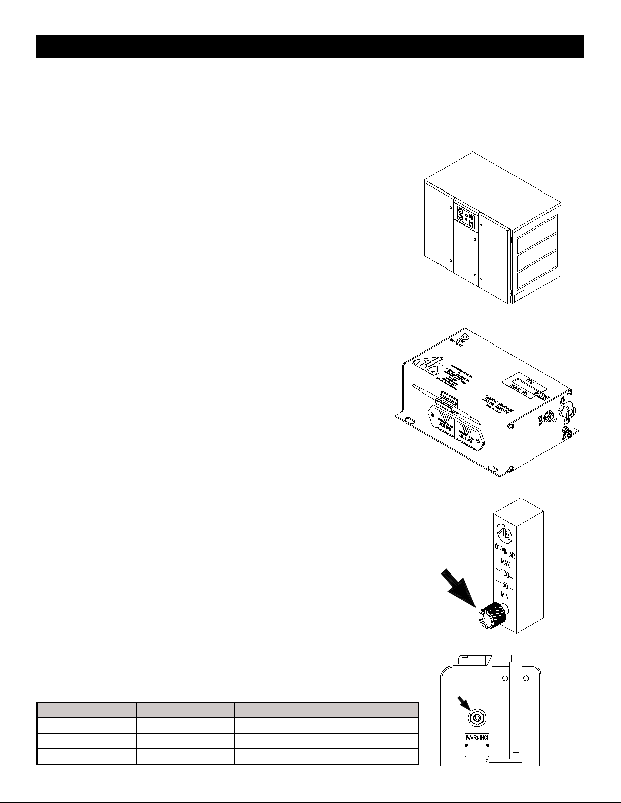
3) Remove air pressure from the box by pulling the relief valve ring out.
4) Turn the CO monitor OFF. Do not remove the 9 volt batteries. These are used to maintain a bias voltage to the sensor.
This keeps the sensor ready for immediate use.
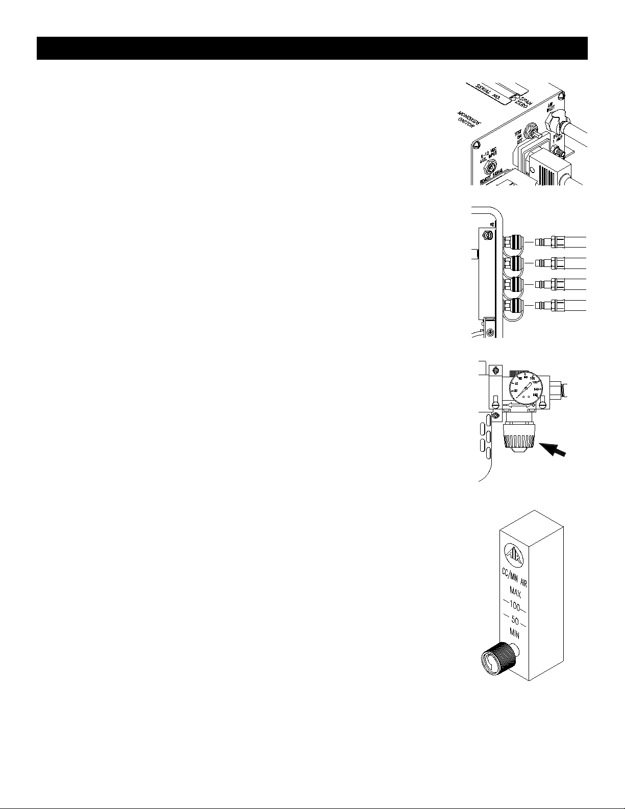
5) Disconnect airline hoses.
6) Install dust caps if applicable.
System Maintenance
Filter Housing/Bowls: Periodic cleaning of the polycarbonate bowls may become necessary. Remove the auto drains and
clean the bowls with a mild soapy solution. The auto drains may also be cleaned with a mild soapy solution at this time.
Dry and reinstall into the lter housing.
Filter Change: The ltration system consists of lter change indicators which will gradually change from green to orange
when lter life is spent.
Note: Air must be owing through the lters before the lter change indicators will function.
Calibration: Monitor calibration should be done monthly or whenever the reading may be questionable. A calibration date
sticker should be af xed for future reference. To obtain an accurate calibration, we recommend the use of Air Systems’
calibration kits.
Part Number:
BBK-10 Canadian calibration kit for CO monitor; 10ppm CO, zero air, regulator and case - 17 liter size.
BBK-20 Calibration kit for CO monitor; 20ppm CO, zero air, regulator and case - 17 liter size.
BBK-20103 Calibration kit for CO monitor; 20ppm CO, zero air, regulator and case - 103 liter size.
DECAL085CD Calibration decal card, contains 14 calibration decals.
To assure sensor accuracy, calibration of monitor is required. If you cannot obtain an accurate calibration, sensor replace-
ment may be necessary. Consult Repair Service Department before ordering.
Part Number:
CO-91NS Replacement CO sensor
CAUTION: Always depressurize the system before performing service.
Monitor Baery Replacement
These batteries provide the required continuous bias voltage to the CO sensor and power the monitor in the event of AC
power loss. If AC and DC power are removed for a period of 2 hours or more, a 1 hour restabilization period is required
as eratic readings may occur.
Battery Replacement: Replace 9 volt batteries when the amber “Low Battery” light illuminates. If the monitor is not used
for 90 days, check the 9 volt batteries and replace if necessary.

11
Replacement sensors are shipped with a metal spring installed between the electrodes. Do not remove the clip until the
sensor is to be installed into the monitor.
Step 1)
Disconnect all external connections.
Remove CO monitor from the unit.
Step 2)
Remove the four screws from the moni-
tor’s left endplate.
Step 3)
Remove endplate to gain access to the
sensor cup.
Step 4)
Remove sensor from sensor cup and remove leads. Take the new
sensor and remove the metal spring. Reattach leads to the proper
colored terminals on the new sensor. Install new sensor into sensor
cup.
Step 5)
Reassemble monitor and reinstall in unit.
Connect all cables and air sample hose.
Allow monitor to stabilize 30 minutes to 1
hour and recalibrate.
SENSING
(RED)
REFER-
ENCE
UNUSED
CONTROL
(BLACK)
Sensor Replacement

CALIBRATION PROCEDURE
Do not use inert gases to zero the monitor. This will cause premature failure of the sensor.
CO Monitor Zero Adjustment
To zero the monitor, follow the steps below. Zero calibration gas should be used to properly “zero” the monitor
and assure that a valid calibration is achieved. If zero adjustment cannot be made as indicated, sensor replacement may
be necessary. After each monitor adjustment outlined in the steps, allow time for the changes to stabilize.
STEP 1)
Place the “ON/OFF/TEST” switch in the “ON” position.
STEP 8)
Allow digital readout to stabilize approximately 15-30
seconds.
STEP 10)
Turn the regulator off and disconnect the regulator from
the zero gas cylinder.
STEP 2)
Allow 30 seconds for the readout to stabilize. The green
indicator will illuminate.
STEP 3)
Hold the “ON/OFF/TEST” switch in the “TEST” position.
The following will occur:
Audible alarm will sound
Green LED will ash
Amber Low Battery indicator on monitor will
illuminate
Red LED will be on
This test ensures the circuitry is operable and continuity
to the sensor is proper. Release the switch.
STEP 4)
Remove the air sample inlet tube.
STEP 5)
Install regulator on the zero air cylinder reference gas.
STEP 7)
Attach the clear tubing with the male plug to the air sam-
ple inlet on the monitor.
STEP 6)
Turn the knob on the regulator counterclockwise to allow
the ow of gas thru the hose. Verify ow of gas thru the
hose via touch or sound.
STEP 9)
Adjust the “zero” adjustment screw (clockwise to increase
or counterclockwise to decrease) until a reading of “00” is
obtained.
12
Calibraon Procedure

CALIBRATION PROCEDURE
CO Monitor Span Adjustment
Use only 10-20ppm CO gas for calibration. Using a higher concentration may decrease accuracy at lower scale readings.
Note: 10ppm gas must be used to satisfy Canadian calibration requirements.
STEP 1)
Install regulator on the CO calibration gas cylinder.
STEP 3)
Connect the plug to the air sample inlet on the monitor.
STEP 2)
Turn the knob on the regulator counterclockwise to allow
the ow of gas thru the hose. Verify ow of gas thru the
hose via touch or sound.
STEP 4)
Allow digital readout to stabilize 15-30 seconds.
STEP 5)
Adjust the “span” adjustment screw (clockwise to in-
crease or counterclockwise to decrease) until the digital
readout reads the same as the concentration (ppm) as
printed on the calibration gas cylinder.
STEP 6)
Turn the regulator off and repeat the “zero” adjustment
procedure. The digital readout should return to a “00”
reading.
The monitor is now calibrated and should be
recalibrated monthly or if accuracy is question-
able. Check local requirements and recalibrate
as required.
13
Calibraon Procedure

14
NOTE: For BB15 series units purchased prior to 06/14, please contact customer service for correct
ordering informaon on replacement lter components.
ITEM # DESCRIPTION PART #
1 FILTER CHANGE INDICATOR WL261
2 FILTER BOWL O-RING WL266
3 “A” FILTER ELEMENT AND O-RING BB30-A
4 “C” FILTER ELEMENT AND O-RINGS BB30-C
5 “D” FILTER ELEMENT AND O-RINGS BB30-D
6AUTO DRAIN ASSEMBLY WL024
7 FILTER BOWL WITH GUARD AND AUTO DRAIN WL264
8 MANUAL DRAIN WL262
9 FILTER BOWL WITH GUARD (NO DRAIN) WL267
Models BB15-COIS and BB30-COIS Filter Breakdown

15
ITEM # DESCRIPTION PART #
1 FILTER CHANGE INDICATOR WL056
2 FILTER BOWL O-RING WL091
3 “A” FILTER ELEMENT AND O-RING BB50-A
4 “C” FILTER ELEMENT AND O-RINGS BB50-C
5 “D” FILTER ELEMENT AND O-RINGS BB50-D
6AUTO DRAIN ASSEMBLY WL024
7 PLASTIC FILTER BOWL WL049
8 METAL FILTER BOWL GUARD WL094
9 MANUAL DRAIN WL153
Models BB50-COIS Filter Breakdown

16
ITEM # DESCRIPTION PART #
1 FILTER CHANGE INDICATOR WL261
2 “A” FILTER ELEMENT AND O-RING BB75-A
3 “C” FILTER ELEMENT AND O-RINGS BB75-C
4 “D” FILTER ELEMENT AND O-RINGS BB75-D
5AUTO DRAIN ASSEMBLY WL024
6 FILTER BOWL WITH AUTO DRAIN WL187
7 MANUAL DRAIN WL262
8 FILTER BOWL WITH MANUAL DRAIN WL188
9 FILTER BOWL O-RING WL189
Models BB75-COIS Filter Breakdown

17
ITEM # DESCRIPTION PART #
1 FILTER CHANGE INDICATOR* WL056
2 FILTER BOWL O-RING WL113
3 “A” FILTER ELEMENT AND O-RING BB100-A
4 “C” FILTER ELEMENT AND O-RINGS BB100-C
5 “D” FILTER ELEMENT AND O-RINGS BB100-D
6AUTO DRAIN ASSEMBLY WL024
7 PLASTIC FILTER BOWL WL055
8 METAL FILTER BOWL GUARD WL092
9 MANUAL DRAIN WL153
NOTE: On MODEL BB100-CO lters (shown above) lter change indicators are on all three
lters. On MODEL BB150-CO only the “C” lter has a lter change indicator.
Models BB100-COIS and BB150-COIS Filter Breakdown

18
Notes:

Air Systems’ manufactured equipment is warranted to the original user against defects in workmanship or materials under
normal use for one year from the date of purchase. Any part which is determined by Air Systems to be defective in mate-
rial or workmanship will be, as the exclusive remedy, repaired or replaced at Air Systems’ option. This warranty does not
apply to electrical systems or electronic components. Electrical parts are warranted, to the original user, for 90 days from
the date of sale. During the warranty period, electrical components will be repaired or replaced at Air Systems’ option.
NO OTHER WARRANTY, EXPRESSED OR IMPLIED, AS TO DESCRIPTION, QUALITY, MERCHANTABILITY, FIT-
NESS FOR A PARTICULAR PURPOSE, OR ANY OTHER MATTER IS GIVEN BY AIR SYSTEMS IN CONNECTION
HEREWITH. UNDER NO CIRCUMSTANCES SHALL THE SELLER BE LIABLE FOR LOSS OF PROFITS, ANY OTHER
DIRECT OR INDIRECT COSTS, EXPENSES, LOSSES, OR DAMAGES ARISING OUT OF DEFECTS IN, OR FAILURE
OF THE PRODUCT OR ANY PART THEREOF.
The purchaser shall be solely responsible for compliance with all applicable Federal, State and Local OSHA and/or MSHA
requirements. Although Air Systems International believes that its products, if operated and maintained as shipped from
the factory and in accordance with our “operations manual”, conform to OSHA and/or MSHA requirements, there are no
implied or expressed warranties of such compliance extending beyond the limited warranty described herein. Product
designs and speci cations are subject to change without notice. Rev. 2, 12/98
Air leaks are not covered under warranty except when they result from a defective system component, i.e. an on/off valve
or regulator or upon initial delivery due to poor workmanship. Air leaks due to poor delivery or damage will be covered un-
der delivery claims. Minor air leaks are part of routine service and maintenance and are the responsibility of the customer
just as are lters and oil changes.
19
Warranty

Printed in the U.S.A. ©Copyright Air Systems International, Inc. 2018 All Rights Reserved
AIR SYSTEMS INTERNATIONAL, INC.
829 Juniper Crescent, Chesapeake, Va 23320
Telephone (757) 424-3967
Toll Free 1-800-866-8100
Fax No. (757) 424-5348
http://www.airsystems.com
Manual No. BREBX021
Rev. 5 April 2018
This manual suits for next models
11
Table of contents
Other AIR SYSTEMS Air Cleaner manuals