-4-
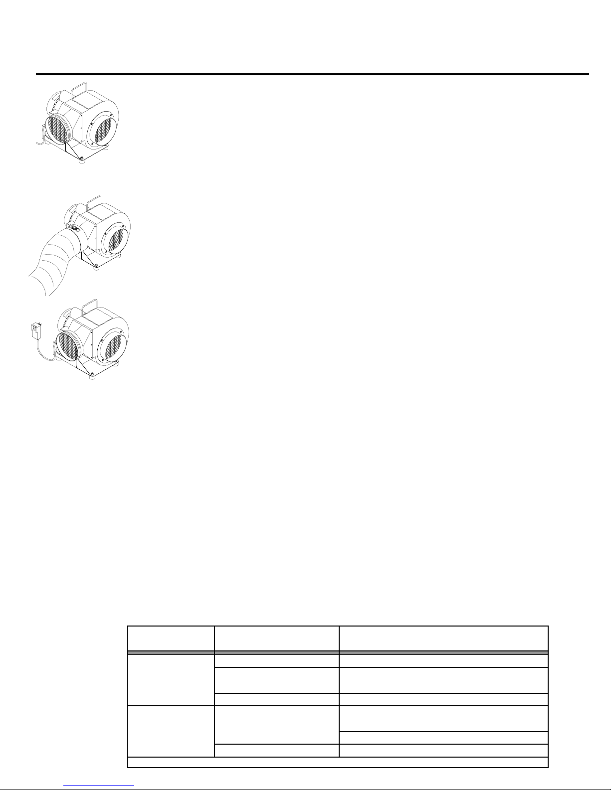
GENERAL SETUP & OPERATION, ELECTRIC BLOWER SERIES
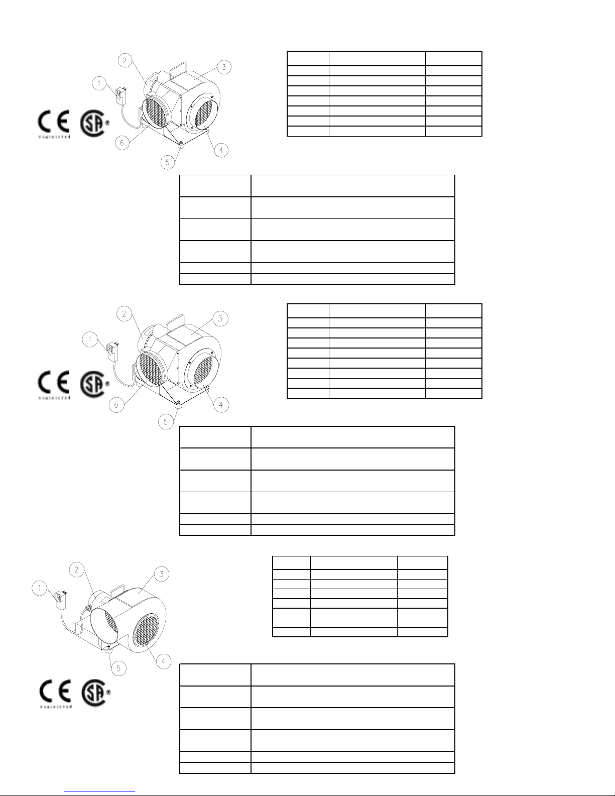
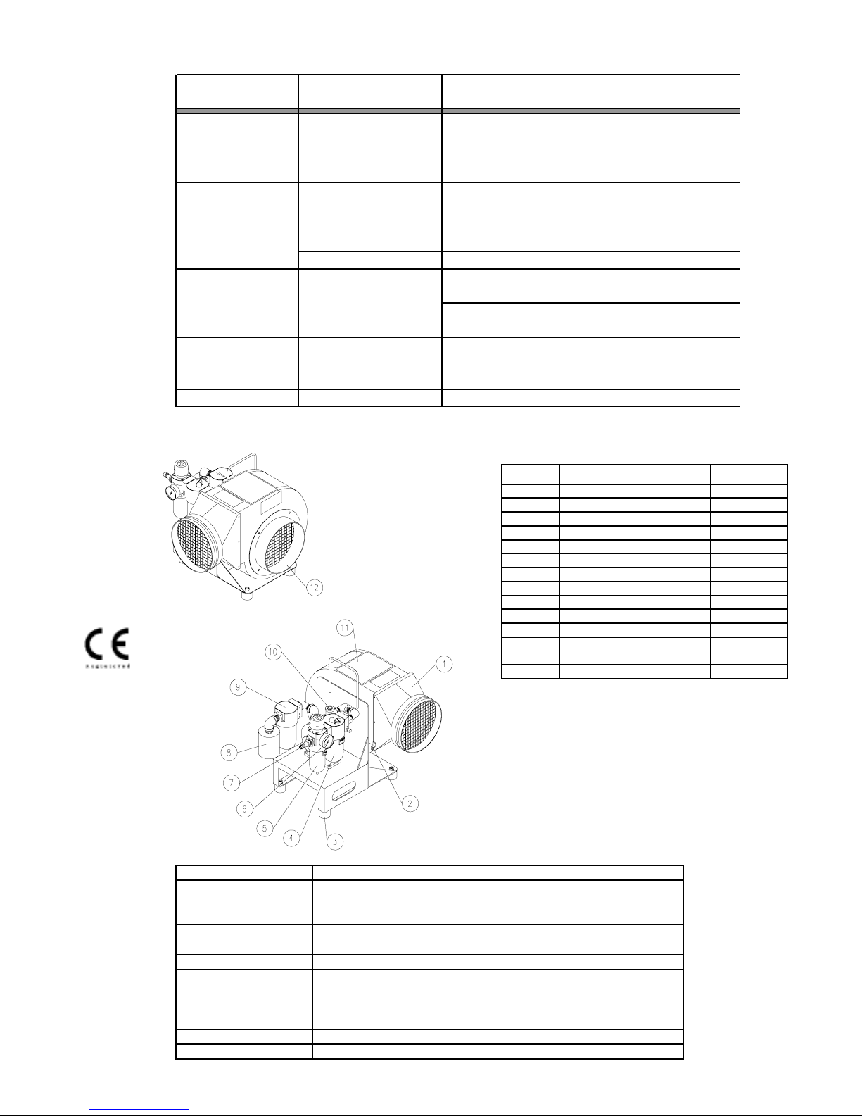
MODELS SVB-E8, SVB-E8-2, & SVB-E8EC
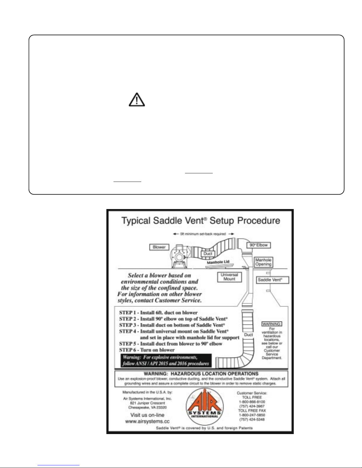
STEP1)
Place blower in a clean fresh air environment. Set blower a minimum of 5 ft. from the
manhole opening. Note: Inspect blower for damaged or worn parts. Inspect all ducting
and couplings for possible air leaks prior to blower operation.
Note: Air quality of the confined space should be tested prior to ventilation. If air
quality of the confined space is unacceptable, consult a trained professional. (Model
SVB-E8EC blower does not come standard with an intake flange. Intake flange can be
purchased as an option from Air Systems Repair Service Department. Order part no.
METL196O.
STEP 2)
Install duct cuff to exhaust flange and tighten cinch strap. Keep bends and kinks in ducting to
a minimum to maximize air flow.
STEP3)
Connectto120VAC, 15amp,60Hzdedicatedservice. All standard electricblowerslistedare
suppliedwithGFI plug(GroundFault Interrupters)perthe 1996NECcode requirement: Section
305-6.
Note: If an extension cord is required, the minimum recommended size is 12 AWG
(Maximum 100 ft.). For further information, refer to the National Electric Code Tables,
Article 400. (The use of generators are not recommended unless they are of sufficient
output capacity. Some generator’s output current will not allow the use of GFI plugs. A
standard 3-prong plug would need to be installed instead of the GFI recepticle).
STEP 4) Push “on/off” (reset) switch, located on the GFI unit, to the “on” position. The
unitisnowoperational.
SHUTDOWN
• Insure that all workers are removed from the confined space site.
• Shut off blower and remove all ducting.
MAINTENANCE
• Keep blower motor dry and free from contaminants and dust.
• Check periodically to ensure moving parts are free from obstructions.
TROUBLESHOOTING
PROBLEM POSSIBLE CAUSE SOLUTION
Excessive vibration Air intake blocked
Turn blower off and clear debris from intake
Possible internal damage Turn blower off and inspect fan blades, shaft, and
housing for debris, damage, and loose screws.
Turn fan off and inspect blower housing
Blower will not start
Wattage output of power source insufficient*
Extension cord improperly sized
*Note: The use of generators are not recommended unless they are of sufficient output capacity.