Air TEc CYPRES User manual

Important information
Please read
english
CYPRES
User’s Guide

CYPRES USER’S GUIDE
Airtec GmbH Page 1
Congratulations on your choice of CYPRES, the safest and most accurate AAD currently
available. CYPRES is the only completely electronic automatic opener on the market, as
well as the smallest and the lightest.
Like most skydivers, you probably assume you will always have time to deploy your reserve
canopy yourself, and that situations requiring use of an automatic opener always happen
to others. We do hope that you will never have such trouble, and that your CYPRES will
never have to take action to save your life.
Should CYPRES ever have to open your reserve, it will most probably happen at a moment
which justifies, no matter how experienced and cautious you are, that you haven't left your
safety to chance.
Airtec GmbH, Safety Systems
Dieses Handbuch ist in deutsch erhältlich.
Ce manuel est disponible en français.
Dit Handboek is ook in het Nederlands verkrijgbar.
Este manual está disponivel em Português.
Este manual está disponible en español.
Questo manuale èdisponibile in italiano.
Ez a kézikönyv magyar nyelven kapható. (Hungarian)
Tento manual je k dostání v èeštinì. (Czech)
Ta instrukcja jest dotstêpna w jêzyku polskim.
Ýòó êíèãó- îïèñàíèÿ ìîæíî ïîëó÷èòü íà ð óññê îì ÿçûêå. (Russian)

CYPRES USER’S GUIDE
Page 2 Airtec GmbH
Contents
page
1. Function ....................................................................................................... 3
1.1 Design philosophy ......................................................................................... 3
1.2 Components .................................................................................................. 4
1.3 How CYPRES works .................................................................................. 5,6
1.4 Energy supply ................................................................................................ 7
1.5 Operational safety .......................................................................................... 8
2. Product Overview ....................................................................................... 9
2.1 Expert CYPRES ............................................................................................ 9
2.2 Student CYPRES ........................................................................................ 10
2.3 Tandem CYPRES ........................................................................................ 10
3. Installation .................................................................................................. 11
3.1 Processing unit ............................................................................................ 12
3.2 Release unit ............................................................................................... 13
3.3 Control unit ......................................................................................... 14,15,16
4. How to Operate CYPRES .......................................................................... 17
4.1 Handling the control unit .............................................................................. 17
4.2 Switching CYPRES on ............................................................................ 18,19
4.3 When to switch on or off .............................................................................. 20
4.4 Changing altitude reference ..................................................................... 21,22
4.5 Water jumps ................................................................................................ 23
5. Errors Display ........................................................................................... 24
6. Maintenance .............................................................................................. 25
6.1 Removal of the unit ...................................................................................... 25
6.2 Replacing battery ........................................................................... 26,27,28,29
6.3 Changing the release unit ............................................................................ 30
6.4 Technical service ......................................................................................... 31
7. Important Notes ......................................................................................... 32
7.1 For jump pilots ............................................................................................. 32
7.2 For users ..................................................................................................... 33
8. Repacking of Reserves ......................................................................... 34,35
8.1 Packing one-pin reserve containers ......................................................... 36,37
8.2 Packing two-pin reserve containers ............................................................. 38
8.3 Packing one-pin Pop Top reserve containers ............................................... 39
8.4 Packing two-pin Pop Top reserve containers .......................................... 40-45
8.4.1 Additional notes to the Racer and Racer Elite .............................................. 46
9. Abbreviated Users' Guide ........................................................................ 47
10. Installation in a New Rig ........................................................................... 48
11. Regarding Air Travel ................................................................................. 49
12. Technical Data ........................................................................................... 50
13. Guarantee .................................................................................................. 51
14. Electromagnetic Compatibility ................................................................ 52
15. Disclaimer .................................................................................................. 53
16. Key Words ............................................................................................. 54,55
17. Packing list ................................................................................................ 56
Trade Marks ............................................................................................... 57

CYPRES USER’S GUIDE
Airtec GmbH Page 3
1. Function
1.1 Design philosophy
CYPRES, which is the acronym of "CYbernetic Parachute RElease System", is an
automatic activation device, which meets all needs and wishes of today's skydivers. Once
it is installed, you can't hear it, you can't feel it and you can't see it.
The operation is quite simple: Just switch it on in the morning prior to the first jump, then
forget about it. It is not necessary to switch it off, because CYPRES will do this itself.
The weather is constantly checked by CYPRES over the day by measuring the air pressure
twice a minute. This means that the unit is always calibrated to the precise ground level.
The Expert CYPRES is designed in a way that it won't restrict the skydiver in any way.
Even with extreme maneuvers during exit and in freefall, CYPRES will cope with it.
Whatever you can think of under canopy like stalls, spiral turns, down planes, hookturns
with the smallest canopies as well as any CRW, CYPRES will analyze these movements
without problems. It won't interfere with any normal activities while skydiving.
Only freefall in very low altitude will cause CYPRES to take action. In this situation CYPRES
will activate the reserve approx. 4.5 seconds prior to impact.
Besides the Expert CYPRES there are the Tandem and Student CYPRES. These models
meet the special requirements of tandem jumps and student training.
From January 1991 to February 2001, CYPRES has saved at least 240 skydivers and 12
tandem students.

CYPRES USER’S GUIDE
Page 4 Airtec GmbH
processing unit
Never ever
- pull
- lift
- carry along or
- dare to throw around
CYPRES by one of its cables.
control unit release unit /
emergency opening
system (EOS)
1.2 Components
CYPRES consists of a microprocessor-based, self-checking processing unit, a control
unit through which prejump altitude adjustments are made, and a release unit (EOS).
Two release units are used on dual-pin systems.
Never attempt to lift or move
the plastic adapter on the end
of the release unit cable which
is plugged into the
processing unit.

CYPRES USER’S GUIDE
Airtec GmbH Page 5
loop small flap for
attachment
1.3 How CYPRES works
Every time CYPRES is switched on it will calibrate to ground elevation by measuring the
air pressure several times in a short period of time and taking the average value as the
value for ground level. This is happening during the integrated self-test. CYPRES doesn't
stop here. While it is in use it will constantly check the air pressure on the ground and, if
necessary, adjust to changing weather, e.g. air pressure. The very accurate calibration is
basis for CYPRES to recognise exactly the activation altitude and activation of the release
elements in case of exceeding activation speed.
The processing unit contains a factory-programmed microprocessor that is capable of
real-time calculations of the jumper's altitude and rate of descent on the basis of barometric
pressure.
By monitoring this data, certain criteria are generated from which conclusions are drawn.
Should the conclusion be that the jumper is in a dangerous situation (i.e. still in freefall at
a low altitude) the processing unit triggers the release unit to open the reserve container.
The release unit or Emergency Opening System (EOS) for the reserve container is
completely independant of the rig's system, because it does not pull the ripcord pin out of
the closing loop but actually cuts the loop inside the reserve container to release the pilot
chute. This method is exclusive to CYPRES.
CYPRES' opening system has these advantages:
•The reserve container can be opened two different ways. One method is used by the
jumper –pulling the reserve release handle; the other method is used by CYPRES
when it cuts the closing loop.
•Mechanical components are reduced to a single movable bolt in the release unit.
Processing and control functions are electronic-based.
•The opening system is situated inside the reserve container where it will not be
exposed to external battering or other adverse influences.
•The system is unobtrusive and can be installed so that it is undetectable from the
outside.
piston

CYPRES USER’S GUIDE
Page 6 Airtec GmbH
Schematic diagram of EOS function:
loop pellet
propellant
piston
plastic coating
stainless
steel body
The distance which the piston moves in case of an activation is approx. 5 mm.
The cutter assembly (EOS) is completely self-contained. In the event of activation, there
is nothing released. It was specially developed for CYPRES, and is classified as being
non-hazardous.

CYPRES USER’S GUIDE
Airtec GmbH Page 7
1.4 Energy supply
CYPRES works with a battery that is calculated to last for approx. two years or approx.
500 jumps. The battery is a high-energy density type, with long life and low self-discharge.
It consists of two round cells, and does not contain heavy metals. Each battery which has
been installed in CYPRES has to be replaced after 2 years at the latest. In case that the
rig or CYPRES will be out of use the battery should be removed and disposed of after 2
years to prevent possible damage. The battery can be replaced by the user, however, the
procedure is tricky and demands considerable attention to detail. See pages 25-29 for full
instructions.
The battery's current voltage is displayed during each activation cycle (see page 18).
After the unit has been switched on, there is a self-test routine during which numbers
beginning with 9999 count down rapidly toward 0. The countdown is interrupted for approx.
three seconds at a value somewhere between 6900 and 5700. This interruption indicates
battery charge. For example, suspension of the countdown at 6300 means that the actual
battery voltage is approx. 6.3 volts.
When the self-test routine is repeated several times within a short interval, the displayed
battery voltage will not be constant. This is normal and has nothing to do with the technical
components of CYPRES but rather, properties of the battery. Typically, the voltage displayed
during a second or third self-test cycle will be lower than the voltage displayed during
initial activation. With further self-test cycles, voltage will rise again.
If the unit has not been used for a long time, the battery voltage shown on the display
during the initial self-test can appear to be rather low. However, the voltage displayed
does not indicate a discharged battery but it is merely due to certain properties of the
battery.
The absence of an electric current over a prolonged period will result in the build-up of an
internal protective layer which will minimize self-discharge.
This layer can be removed by simply switching the unit on and off a couple of times. You
will then see that the battery voltage shown during self-test will rise again.
Battery failure or low battery voltage will be detected by CYPRES. At the end of the self-
test cycle, CYPRES will stop with an error display of 8999 or 8998 and will not assume
operating mode. This indicates that the energy supply of the battery is no longer within
operational limits.
Replace the battery once the self test has stopped at 8998
or 8999 (voltage too low), after two years or after 500 jumps
whichever comes first.

CYPRES USER’S GUIDE
Page 8 Airtec GmbH
1.5 Operational safety
There are two important points to remember regarding the operational safety of CYPRES:
1. CYPRES self-tests automatically every time it is switched on. After every switching-
on procedure, CYPRES executes a self-test routine during which all important internal
functions are checked. Usually, a positive outcome to this self-test should assure
you of troublefree operation for up to 14 hours.
When the display unit shows 0 , the self-test has been completed successfully. If the
self-test has resulted in errors or discrepancies, CYPRES will not assume operating
mode but will switch itself off while displaying an error code. This error code indicates
why the activating process was abandoned (see page 24).
2. CYPRES has fail-safe error detection. Two processes are activated in CYPRES once
the unit has been switched on: a primary working process and an independently
operating controlling process that monitors the working process continuously. In case
of errors while the working process is active, the back-up controlling process will
switch the unit off.
Depending on the type and potential impact of the error, CYPRES can either be
switched on again or it will stay in shut-down mode permanently. With certain error
codes (see error code list on page 24), it is not possible for the user to reactivate the
unit. In such cases, CYPRES must be sent back to the manufacturer for inspection
and adjustment.
Remember: A positive outcome of the self-test should assure you a troublefree
operation for up to 14 hours.
.

CYPRES USER’S GUIDE
Airtec GmbH Page 9
2. Product Overview
CYPRES is available in six models:
Expert CYPRES for one-pin-container
Expert CYPRES for two-pin-container
Student CYPRES for one-pin-container
Student CYPRES for two-pin-container
Tandem CYPRES for one-pin-container
Tandem CYPRES for two-pin-container
Meter/Feet version
Every CYPRES model is offered with an altitude calibration either in feet (30-feet steps)
or in meters (10-meter steps). The different versions can only be distinguished from each
other when the reference altitude is changed; otherwise, they are identical.
The "feet" version will display thirty (30) as a step difference, while the meter version will
show a step interval of ten (10). See pages 21-22 for changes of reference altitude.
2.1 Expert CYPRES
The Expert CYPRES can be recognized by the red button on the control unit.
It activates the EOS when it detects a rate of descent higher than 78 mph (35 m/sec) at
an altitude of apx 750 feet above ground level (AGL). In the event of a breakaway below
this height CYPRES will operate down to apx 130 feet AGL. Below 130 feet AGL opening
is no longer useful. For this reason, CYPRES ceases operation below apx 130 feet AGL.

CYPRES USER’S GUIDE
Page 10 Airtec GmbH
2.3 Tandem CYPRES
The Tandem CYPRES can be recognized by the blue button with the imprint "Tandem" on
the control unit.
It activates the EOS when it detects a rate of descent higher than 78mph (35m/sec) at an
altitude of apx 1900 feet AGL.
2.2 Student CYPRES
The Student CYPRES can be recognized by the yellow button with the imprint "Student"
on the control unit.
It will activate the EOS when the rate of descent exceeds 29mph (13m/sec). The activation
altitude is split. In the case of rate of descent being equal to that of freefall the opening
altitude is at approx. 750 feet, being the same as with Expert CYPRES. However, should
the rate of descent be lower than that of freefall but still above the limit of 29mph (e.g. with
partially opened canopy), then Student CYPRES activates the EOS when the altitude
decreases below 1000 feet above ground level. The student will then have some more
time to prepare for landing.
If a jump plane is descending without having
dropped, switch the Student CYPRES off!
Be aware that it is possible to exceed a
vertical speed of 29 mph under a fully inflated
canopy!
Unlike the Expert CYPRES models, we recommend that the Student CYPRES be switched
off in the aircraft prior to descent if the jump is aborted and the student will land with the
plane.

CYPRES USER’S GUIDE
Airtec GmbH Page 11
3. Installation
CYPRES MUST ONLY BE INSTALLED BY A QUALIFIED RIGGER WHO HAS BEEN
AUTHORIZED BY AIRTEC FOR SUCH INSTALLATION. IN RIGS WITH CYPRES
SET-UP, CYPRES CAN BE MOUNTED BY ANY RIGGER OR RESERVE PACKER.
Definitions:
Installation: Doing a retrofit, sewing the pouch, cutter elastic(s), and cable housings into
a container without CYPRES Set-up.
Mounting: Assembling the CYPRES into a container with an existing approved set-up.
CYPRES can be installed in rigs without adding to pack volume or changing their exterior
profile. Both the processing unit and EOS are mounted inside the reserve container, while
the control unit is placed either underneath the top flap next to the ripcord pin, or on the
front of the harness to allow for easy access.
Because CYPRES is designed to fit within minimum volume requirements, thereby saving
space wherever possible, its tolerance of abuse has been minimized in anticipation of
careful handling by the user. For this reason, it is imperative to avoid twisting or pulling
forces on the cable connections during installation or removal, as well as during normal
usage.
In the following sections (3.1, 3.2 and 3.3) you will find additional information regarding
installation of the three components that make up CYPRES. However, CYPRES must be
installed only by a qualified rigger who has been authorized by Airtec for such installation.
The "CYPRES Rigger's Guide for Installation" contains detailed instructions for the
procedure, and the necessary tools are provided with a special rigger's kit.
It is of utmost importance for your safety that CYPRES be installed strictly according to
the Rigger's Guide for Installation.
Should you obtain your CYPRES in a state readily installed, please make sure
that you have a CYPRES reserve loop together with a disc and a CYPRES pull-
up (two with two-pin CYPRES; plus 2 soft bodkins with two-pin Pop Tops) stored
in the CYPRES pocket of your container.
Further, be sure that you get the following parts along with your CYPRES:
1 CYPRES reserve loop, 1 CYPRES pull-up (2 with 2-pins), 2 special packing
bands (only with two-pin Pop Tops).
control unit
processing unit (mid position)
release unit (EOS)
reserve container

CYPRES USER’S GUIDE
Page 12 Airtec GmbH
3.1 Processing unit
The processing unit must be positioned centrally on the partition wall separating the
main and reserve containers, so that the reserve canopy material covers and surrounds
the unit on all sides. This offers the best protection against temperature variations and
impact damage.
For installation, the processing unit is placed into a specially bolstered and labeled nylon
pocket which is supplied with every CYPRES.
Excess cable is stowed in the flat part of the pocket underneath the velcro-adjustable flap.
If you have to stow both the thinner EOS cable and thicker cable to the control unit, be
sure to place the thicker cable so that it lays on top of the thinner one. Cables should be
placed in a circle in order to avoid twists. Always avoid pulling, bending, twisting, or kinking
the cables.
wall separating
main and reserve
container
processing unit
(middle position)
right wrong
When placing the processing unit into its nylon pouch, make sure that the cables lie flat
on the bottom.

CYPRES USER’S GUIDE
Airtec GmbH Page 13
3.2 Release unit
Installation of the release unit (EOS) varies from system to system, depending on the
design. Detailed information is contained in the "Rigger's Guide for Installation" and in
individual equipment manufacturers instruction booklets.
To ensure correct operation of the release unit (EOS) the reserve closing loop(s) must be
made of the correct diameter Polyamide material and the top except for 1/2" above the
disc must also be silicone impregnated (but see page 39 for special instructions concerning
single pin pop-top containers). The silicone reduces wear and tear and increases flexibility
of the loop. Furthermore, the force needed to pull the reserve ripcord pin is reduced.
Loops supplied by Airtec are pre-treated on the first 2".
release unit (EOS)
The release elements have to be mounted like described in the CYPRES
Rigger’s Guide for Installation.
NOTE: WHEN CYPRES IS INSTALLED ONLY USE RESERVE CLOSING LOOPS
SUPPLIED BY AIRTEC.

CYPRES USER’S GUIDE
Page 14 Airtec GmbH
3.3 Control unit
The control unit
is placed underneath the top flap next to the ripcord pin.
.
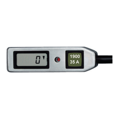
4 digit display LED light push button
control unit
pin
control unit
pin

CYPRES USER’S GUIDE
Airtec GmbH Page 15
The control unit should be attached using the four small nylon ties built into its bottom
surface. These ties can be pulled through nylon layers with a needle and then secured
with appropriate knots.
This method of attachment places the knots out of sight and is therefore visually pleasing.
Alternatively the transparent pouch (supplied with the installation kit) can be hand sewn or
machine stitched under the reserve top flap. The control unit is then pushed into the
pouch and not sewn directly to the rig.
control unit
thread
nylon
knots
When inserting your hand-deploy in a pilot chute pouch on the bottom of the
container do not turn the rig upside down. This can damage the control unit cable
if the control unit is located in the collar area of the rig.

CYPRES USER’S GUIDE
Page 16 Airtec GmbH
An alternative method for mounting the control unit is to use the velcro strip supplied with
the unit.* Both velcro components have an adhesive coating.
For added security we recommend that the pile portion of the velcro (velcro 2) is secured
to the rig by sewing or tacking in addition to the adhesive. The use of velcro raises the
control unit by four (4) millimeters.
Once the control unit has been mounted, make sure that it cannot interfere with the reserve
container opening, the ripcord, the pin(s).
Inside the reserve container, the nylon pockets supplied with CYPRES must be used to
install both processing and release units. The nylon cable housing should be used to
encase all cable. You will find these installation components in one of the plastic bags.
NOTE: CYPRES MUST ONLY BE INSTALLED BY A QUALIFIED RIGGER WHO HAS
BEEN AUTHORIZED BY AIRTEC FOR SUCH INSTALLATION.
control unit
velcro I
velcro II
*since 1.1.98 only supplied on request

CYPRES USER’S GUIDE
Airtec GmbH Page 17
4. How to Operate CYPRES
4.1 Handling the control unit
The pushbutton on the control unit should be pressed with the fingertip alone; please do
not use a fingernail. Use a short pushing action in the middle of the button (like a click).
You should familiarize yourself with switching CYPRES on and off and changing reference
altitudes (pages 17, 18, 20 and 21) prior to installing and using it.
The pushbutton is the only means the user has for controlling CYPRES functions. Through
it, the following four actions are initiated:
•switching on
•switching off
•increasing reference altitude
•decreasing reference altitude
The following pages provide thorough descriptions of these four procedures.

CYPRES USER’S GUIDE
Page 18 Airtec GmbH
4.2 Switching CYPRES on
CYPRES is switched on by pressing the pushbutton four times with short dry clicks. You
initiate the switching-on cycle by clicking the button once. After approx. one second, the
red LED-light will glow. You must acknowledge the red light immediately by clicking the
button again. This sequence —a click following appearance of the red light —will be
repeated two more times. After a total of four clicks, CYPRES goes into operating mode.
If you do not act promptly after seeing the LED-light, or if you push the button too soon,
CYPRES will ignore the switch-on attempt. Simply try again —it's easy once you've done
it.
This four-click initiation cycle has been designed to avoid accidental activation.
Once the switching on procedure is finished, the unit will run through its self-test. Initially
the display will show the number 9999, and then a rapid countdown ending in 0. The
countdown will take 29 seconds, and will be interrupted three times.
There will be a three-second pause between the numbers 6900 and 5700. The number
displayed at this pause will indicate the actual battery voltage (e.g. 6300 means 6.3 volts).
The second and third pause will last approx. one second each, and will occur at 5000 and
100. These pauses are for technical reasons only and have no meaning to the user.
During its self-test, CYPRES will measure the air pressure several times. Should the unit
detect large differences between pressure values, it will conclude that there is a problem
and will not proceed to operating mode. In such a case, it will abort its self-test and display
the number 100.
LED light
coming up
LED light
coming up
LED light
coming up
wait wait wait
click
click
clickclick
self-test and
calibration
unit
switched on

CYPRES USER’S GUIDE
Airtec GmbH Page 19
Any functional defect will also cause CYPRES to abort the self-test and display a number
for approx. two seconds before switching itself off. This number is an error code. Error
code numbers are listed on page 24 along with their respective causes.
After the self-test has been completed or after you've switched off the unit, CYPRES will
ignore further inputs for one second.
Once activated, CYPRES will remain in operating mode for 14 hours, after which it will
switch itself off. Of course the unit can be switched off manually at any time.
The manual switch-off sequence is the same as the switch-on procedure. Again, this
routine is designed to avoid accidental deactivation.
Other manuals for CYPRES
2
Table of contents
Other Air TEc Measuring Instrument manuals

Air TEc
Air TEc SUTO S600 Manual

Air TEc
Air TEc Expert CYPRES 2 User manual

Air TEc
Air TEc Expert CYPRES 2 User manual

Air TEc
Air TEc Expert CYPRES 2 User manual

Air TEc
Air TEc 89NAH User manual

Air TEc
Air TEc Expert CYPRES 2 User manual

Air TEc
Air TEc Expert CYPRES 2 User manual

Air TEc
Air TEc Expert CYPRES 2 User manual