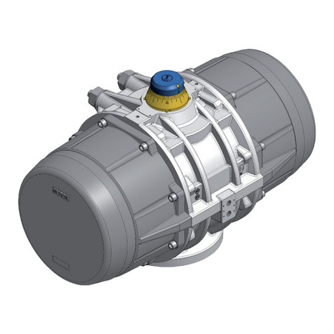
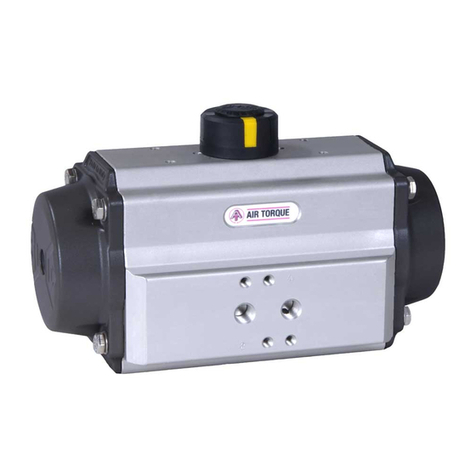
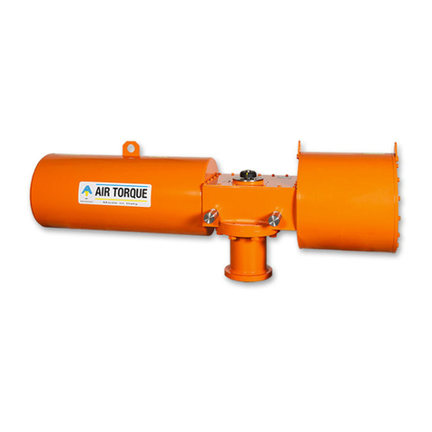
Air Torque AT-HDC Series Service manual

Original instructions
EB AT-HDC EN
AT-HDC series
Compact scotch yoke pneumatic actuators
Edition December 2022

Note on these mounting and operating instructions
These mounting and operating instructions assist you in
mounting and operating the device safely. The instructions
are binding for handling AIR TORQUE devices. The images
shown in these instructions are for illustration purposes only.
The actual product may vary.
ÎFor the safe and proper use of these instructions, read
them carefully and keep them for later reference.
ÎIf you have any questions about these instructions, con-
tact AIR TORQUE‘s After-sales Service Department
The mounting and operating instructions
for the devices are included in the scope of
delivery. The latest documentation is avail-
able on our website at www.airtorque.it
Definition of signal words
Hazardous situations which, if not avoided, will result in death
or serious injury
Hazardous situations which, if not avoided, could result in
death or serious injury
Property damage message or malfunction
Additional information
Recommended action
DANGER
!
WARNING
!
NOTICE
!
Note
Tip
EB AT-HDC EN

EB AT-HDC EN
Contents
1 Safety instructions and measures ................................................................................................................. 1-1
1.1 Notes on possible severe personal injury ....................................................................................................... 1-2
1.2 Notes on possible personal injury ................................................................................................................. 1-2
1.3 Notes on possible property damage ............................................................................................................. 1-2
1.4 Warnings on the device ............................................................................................................................... 1-3
2 Markings on the device ............................................................................................................................... 2-1
2.1 Actuator nameplate ..................................................................................................................................... 2-1
2.1.1 Standard nameplate sample ......................................................................................................................... 2-1
2.1.2 PED marked nameplate sample .....................................................................................................................2-3
2.2 Functioning label sample ..............................................................................................................................2-4
3 Design and principle of operation ................................................................................................................ 3-1
3.1 Direction of action and fail position .............................................................................................................. 3-1
3.2 Complementary parts ...................................................................................................................................3-1
3.3 Technical data ............................................................................................................................................. 3-2
4 Shipment and on-site tranport ..................................................................................................................... 4-1
4.1 Accepting the delivered goods ......................................................................................................................4-1
4.2 Removing the packaging from the actuator .................................................................................................... 4-1
4.3 Transporting and lifting the actuator .............................................................................................................. 4-1
4.3.1 Transporting the actuator ..............................................................................................................................4-1
4.3.2 Lifting the actuator ....................................................................................................................................... 4-1
4.4 Storing the actuator ..................................................................................................................................... 4-2
5 Mounting and assembly .............................................................................................................................. 5-1
5.1 Preparation for installation ........................................................................................................................... 5-1
5.2 Control and signal devices assembly ............................................................................................................. 5-1
5.3 Mounting the actuator over the valve .............................................................................................................5-1
6 Start-up ...................................................................................................................................................... 6-1
7 Operation ...................................................................................................................................................7-1
8 Malfunctions ............................................................................................................................................... 8-1
8.1 Troubleshooting ........................................................................................................................................... 8-1
8.2 Emergency action ........................................................................................................................................ 8-1
9 Service ....................................................................................................................................................... 9-1
9.1 Preparation for servicing .............................................................................................................................. 9-2
9.2 Part List ...................................................................................................................................................... 9-2
9.3 Disassembly ................................................................................................................................................ 9-3
9.3.1 Stroke adjustment screws removal ................................................................................................................ 9-3
9.3.2 (W) Welded central module configuration disassembly ................................................................................... 9-3
9.3.2.1 Cover removal ............................................................................................................................................ 9-3
9.3.2.2 Central module disassembly ......................................................................................................................... 9-3
9.3.3 (C) Casted central module configuration disassembly ......................................................................................9-6
9.3.3.1 Cover removal ............................................................................................................................................ 9-6
9.3.3.2 Central module disassembly ......................................................................................................................... 9-6
9.3.4 Power module disassembly ........................................................................................................................... 9-9
9.3.5 Piston disassembly ....................................................................................................................................... 9-9
9.4 Service operations ....................................................................................................................................... 9-10
9.5 Reassembly ................................................................................................................................................. 9-10
9.4.1 Piston reassembly ....................................................................................................................................... 9-10
9.4.2 Power module reassembly ........................................................................................................................... 9-11
9.4.3 (W) Welded central module configuration reassembly .................................................................................... 9-12
9.4.3.1 Central module reassembly .......................................................................................................................... 9-12
9.4.3.2 Cover reassembly ........................................................................................................................................ 9-14
9.4.4 (C) Casted central module configuration reassembly .......................................................................................9-15
9.4.4.1 Central module reassembly ...........................................................................................................................9-15
9.4.4.2 Cover reassembly ........................................................................................................................................ 9-17
9.4.5 Stroke adjustment screws reassembly .............................................................................................................9-17
9.4.6 Stroke adjustment ....................................................................................................................................... 9-17
9.4.7 Mounting the actuator over the valve ........................................................................................................... 9-17

4 EB AT-HDC EN
10 Decommissioning ........................................................................................................................................ 10-1
11 Removal ..................................................................................................................................................... 11-1
12 Repairs .......................................................................................................................................................12-1
13 Disposal ..................................................................................................................................................... 13-1
14 Certificates ................................................................................................................................................. 14-1
15 Annex ........................................................................................................................................................ 15-1
15.1 Tools ........................................................................................................................................................... 15-1
15.2 Tightening torques and sequences ................................................................................................................. 15-2
15.3 Lubricants ....................................................................................................................................................15-4
15.4 Threadlocker ............................................................................................................................................... 15-4

EB AT-HDC EN 5

EB AT-HDC EN 1-1
Safety instructions and measures
1 Safety instructions and measures
Intended use
The AIR TORQUE AT-HDC Series actuators are intended for
the automation and operation of quarter-turn valves such as
butterfly valves, ball valves and plug valves in both indoor
and outdoor applications. Depending on the configuration,
the actuator is suitable for on/off or modulating duties. The
actuator can be used in processing and industrial plants.
The actuator is designed to operate under exactly defined
conditions (e.g. temperature, pressure, travel). Therefore,
operators must ensure that the actuator is only used in
operating conditions that meet the specifications used for
sizing the actuator at the ordering stage. In case operators
intend to use the actuator in other applications or conditions
than specified, contact AIR TORQUE.
AIR TORQUE does not assume any liability for damage
resulting from the failure to use the device for its intended
purpose or for damage caused by external forces or any
other external factors.
ÎRefer to the technical data and nameplate for limits and
fields of application as well as possible uses.
This manual is intended to be used with standard AT-HDC
Series actuators, for special configurations please contact AIR
TORQUE.
Reasonably foreseeable misuse
The actuator is not suitable for the following applications:
−Use outside the limits defined during sizing and by the
technical data
−Use outside the limits defined by the accessories connected
to the actuator
Furthermore, the following activities do not comply with the
intended use:
−Use of non-original spare parts
−Performing service and repair work not described in these
instructions
Qualifications of operating personnel
The actuator must be mounted, started up, serviced and re-
paired by fully trained and qualified personnel only; the ac-
cepted industry codes and practices are to be observed. Ac-
cording to these mounting and operating instructions, trained
personnel refers to individuals who are able to judge the work
they are assigned to and recognize possible hazards due to
their specialized training, their knowledge and experience as
well as their knowledge of the applicable standards.
Personal protective equipment
We recommend wearing the following personal protective
equipment when handling the AIR TORQUE actuators:
−Protective gloves and safety footwear when mounting or
removing the actuator
−Eye protection and hearing protection while the actuator is
operating.
ÎCheck with the plant operator for details on further protec-
tive equipment.
Revisions and other modifications
Revisions, conversions or other modifications of the product
are not authorized by AIR TORQUE. They are performed at
the user‘s own risk and may lead to safety hazards, for ex-
ample. Furthermore, the product may no longer meet the re-
quirements for its intended use.
Safety devices
The AIR TORQUE actuators alone do not have any special sa-
fety equipment.
Warning against residual hazards
To avoid personal injury or property damage, plant operators
and operating personnel must prevent hazards that could be
caused in the actuator by the signal pressure, stored spring
energy or moving parts by taking appropriate precautions.
They must observe all hazard statements, warning and cauti-
on notes in these mounting and operating instructions.
Responsibilities of the operator
The operator is responsible for proper operation and compli-
ance with the safety regulations. Operators are obliged to
provide these mounting and operating instructions as well as
the referenced documents to the operating personnel and to
instruct them in proper operation.
Furthermore, the operator must ensure that operating person-
nel or third persons are not exposed to any danger.
These instructions should not supersede or replace any custo-
mer’s plant safety or work procedures. If a conflict arises bet-
ween these instructions and the customer’s procedures, the dif-
ferences should be resolved in writing between an authorized
customer‘s representative and an authorized AIR TORQUE re-
presentative.
Responsibilities of operating personnel
Operating personnel must read and understand these moun-
ting and operating instructions as well as the referenced docu-
ments and observe the specified hazard statements, warnings
and caution notes. Furthermore, the operating personnel must
be familiar with the applicable health, safety and accident
prevention regulations and comply with them.
Referenced standards and regulations
−AIR TORQUE actuators are designed, produced and clas-
sified according to the European Atex directive 2014/34/
EU and U.K. Regulation S.I. 2016 No. 1107 (as amen-
ded). Before using the actuators in potentially explosive at-
mosphere areas, verify the actuator compliance with the
required ATEX and UKCA classification.
ÎRefer to the nameplate and the ATEX / UKCA safety inst-
ructions.
−AT-HDC Series actuators are SIL certificated.
ÎRefer to the SIL Certificate available from AIR TORQUE for
the AT-HDC Series actuators SIL capability.
−Referring to Machine Directive 2006/42/EC and U.K. Re-
gulation S.I. 2008 No. 1597 (as amended), actuators are
1-2 EB AT-HDC EN
Safety instructions and measures
classified as “partly machinery” (see Declaration of incor-
poration). Therefore, the actuators cannot be put into ser-
vice until the machinery and/or the final system, where
the actuators are incorporated, will be declared in compli-
ance with the requirements of the Directive.
−The AIR TORQUE pneumatic actuators are designed ac-
cording to the criteria of
- Article 1, paragraph 2. j) ii) of the Pressure equipment
directive (PED) 2014/68/EU.
- Part 1, section 4, schedule 1, paragraph 1. j) ii) of U.K.
Regulation S.I. 2016 No. 1105 (as amended).
Therefore, according to the directive 2014/68/EU and
U.K. Regulation S.I. 2016 No. 1105 (as amended) they
are not to be considered pressure equipments.
ÎRefer to the EU Declaration of Conformity available from
AIR TORQUE.
Referenced documentation
The further documents apply in addition to these mounting
and operating instructions:
−Mounting and operating instructions for the valve, availa-
ble from the valve manufacturer,
−Mounting and operating instructions for control and signal
devices (positioner, solenoid valve, etc.) available from de-
vices manufacturer,
−ATEX safety manual,
−SIL safety manual for use in safety-instrumented systems.
1.1 Notes on possible severe personal in-
jury
DANGER
!
Risk of bursting due to incorrect opening of pressurized
equipment or components.
Pneumatic actuators are pressure equipment that may burst
when handled incorrectly. Flying projectile fragments or com-
ponents can cause serious injury or even death.
ÎBefore starting any work on the actuator disconnect all
pneumatic/hydraulic/electrical supplies and discharge the
pressure from the actuator.
Risk of severe personal injury due to suspended loads fal-
ling.
ÎStay far from suspended or moving loads.
ÎClose off and secure the transport paths.
1.2 Notes on possible personal injury
WARNING
!
Risk of lifting equipment tipping over and risk of damage to
lifting accessories due to exceeding the rated lifting capa-
city.
ÎUse only approved lifting equipment and accessories who-
se maximum lifting capacity is higher than the actuator
weight (including the packaging, if applicable).
Crush hazard arising from moving parts.
The actuator and the valve assembly contains moving parts,
which can injure hands or ngers.
ÎDo not touch or insert hands or nger into moving parts.
ÎBefore starting any work on the actuator disconnect all
pneumatic/hydraulic/electrical supplies and discharge the
pressure from the actuator.
ÎDo not touch or insert hands or nger into the yoke while
the power supply is connected to the actuator.
Risk of personal injury during actuator air exhaust.
In case of pneumatic power cylinder conguration the actua-
tor is operated with air. As a result, air is exhausted during
operation.
ÎInstall the air exhaust components in such a way that
exhaust ports are not located at eye level and the actuator
does not discharge at eye level in the working position.
ÎUse suitable silencers and vent plugs.
ÎWear eye and hearing protection when working near the
actuator.
Risk of personal injury due to compressed springs.
Power modules are under tension due to compressed springs.
Consequently, the disassembly could result in serious injury.
ÎBefore starting any work on the actuator disconnect all
pneumatic/hydraulic/electrical supplies and discharge the
pressure from the actuator.
ÎThe actuator must be in the fail position while removing
the Power module from the Central module.
ÎIf Power module service is necessary, contact AIR TOR-
QUE.
Risk of personal injury through incorrect operation, use or
installation as a result of information on the actuator being
illegible.
Over time, markings, labels and nameplates on the actuator
may become covered with dirt or become illegible in some
other way. As a result, hazards may go unnoticed and the
necessary instructions not followed. There is a risk of personal
injury.
ÎKeep all relevant markings and inscriptions on the device
in a constantly legible status.
ÎImmediately renew damaged, missing or incorrect name-
plates or labels.

EB AT-HDC EN 1-3
Safety instructions and measures
1.3 Notes on possible property damage
NOTICE
!
Risk of actuator damage due to incorrectly attached slings.
ÎDo not attach load-bearing slings to the handwheel or to
the travel stop.
Risk of actuator damage due to the use of inappropriate
tools.
Certain tools are required to work on the actuator.
ÎDo not use damaged tools. Refer to section 15.1 ‘Tools‘.
Risk of actuator damage due to excessively high or low tigh-
tening torques.
Observe the specied torques on tightening actuator compo-
nents (bolts and nuts). Tightening torques above the limits lead
to parts wearing out quicker. Parts that are not tightened
enough may loosen.
ÎRefer to section 15.2 ‘Tightening torques and sequences‘.
Risk of actuator damage due to the use of unsuitable
lubricants.
The lubricants to be used depend on the actuator material and
operating temperatures. Unsuitable lubricants may corrode
and damage the components.
ÎUse only lubricants approved by AIR TORQUE . Refer to
section 15.3 ‘Lubricants‘.
1.4 Warnings on the device
Warning Meaning of the warning Location on the device
Warning against the incorrect use of the lifting bra-
ckets on AIRTORQUE actuators.
Only attach load-bearing slings to them to vertically lift
the actuator on its own (without the valve).
The lifting brackets must not be used to vertically lift si-
multaneously the valve and the actuator.

1-4 EB AT-HDC EN
Safety instructions and measures

EB AT-HDC EN 2-1
Markings on the device
2 Markings on the device
Fig. 2–1
Fig. 2–2
B
A
2.1 Actuator nameplate
Refer to Fig. 2-1 for the location of the standard nameplate or with PED on the actuator.
07
01
04
05
09
19
17
14
06
08
10
11
12
13
16
03
03
07
01 02
04
18
05
06
09
20
19
17
08
10
11
12
13
14
16
15
15

2-2 EB AT-HDC EN
Markings on the device
Table 2-1
Position Description
01 Manufacturer name and trade mark
02 Country of origin
03 Actuator model
04 Fail action
05 Actuator interface
06 Actuator serial number
07 Actuator production date: month/year
08 Fluid (Supply medium)
09 Operating temperature
10 Supply pressure range (if available - marked on request) [bar/psi/kPa]
11 Maximum operating pressure (MOP) [bar/psi/kPa]
12 Actuator maximum output torque at MOT [Nm/Lb•in]
13 Tag number (customer tag number if required)
14 ATEX marking - 2014/34/EU directive
15 EX or CE+EX logo
16 SIL marking - IEC 61508
17 IP marking - IEC 60529
18 QR code
19 UKCA marking - UKSI 2016:1107
20 PED marking - 2014/68/EU directive (Only if applicable).
Refer to the Catalogue HDC-E for actuators available options and ordering codes.
2.2 Functioning label sample
The functioning label is placed in Fig. 2-1 (Position B) over the Power module.
The picture represent an actuator in Fail Close configuration
Fig. 2–3
Refer to section 1.4 for warning labels content and position over the actuator.
Note
Note

EB AT-HDC EN 2-3
Markings on the device

EB AT-HDC EN 3-1
Design and principle of operation
3 Design and principle of operation
The AT-HDC actuators are devices for remote operation (on/
off or modulating duties) of different industrial valves such as
ball valves, butterfly valves and plug valves.
The actuators are available in two configurations: double ac-
ting and single acting.
1. DOUBLE ACTING
In case of double acting, air pressure is necessary to stroke
the actuator in both opening and closing directions (Fig. 3-1).
port 4 port 2
Fig. 3-1
port 4 port 2
2. SINGLE ACTING
Refer to principle of operation (Fig. 3-2).
Air supplied through Port 2 (A) applies a linear force on the
piston surface generating the yoke rotation and driving the
valve to a defined position. At the same time the actuator
spring is compressed exhausting the air through Port 4.
When air pressure is discharged through Port 2 (B), the
spring is automatically released, driving the yoke and the pis-
ton back to the original position and thus the valve to the
fail-safe position.
A
B
Fig. 3-2
port 4
port 4
The AT-HDC actuators can be controlled by directly mounted
devices or remote control systems.
ÎRefer to section 5.2 ‘Control and signal devices assembly‘.
3.1 Direction of action and fail positions
The standard rotating direction for the AT-HDC actuators is
clockwise to close from TOP VIEW.
Standard AT-HDC actuators are designed for 90° rotating
angle, with travel stop allowing adjustment (Fig. 3-3) for ±5°
on both the close (0°) and open (90°) position.
Fig. 3-3
0°
90°
95° 85°
Available stroke
adjustment
-5°
5°
For single acting actuator in case of pressure, power or signal
failure the spring drive the actuator in the fail position that
can be FAIL OPEN, FAIL CLOSE or in an INTERMEDIATE
POSITION according to the control system.
If the actuator is controlled by a control system the FAIL positi-
on may be different from FAIL CLOSE or FAIL OPEN.
ÎRefer to the actuator model technical data for the FAIL po-
sition.
ÎRefer to section 2.1 ‘Actuator nameplate‘ for the fail acti-
on and direction of rotation available options.
3.2 Complementary parts
Manual override systems
Manual override systems are designed to provide manual
operation to drive the actuator and the valve in the safe
position, in case of any emergency situation, when the supply
pressure is not available.
Risk of actuator damage due to incorrect stroke adjustment.
− Make sure that the actuator and the manual override are
correctly oriented, with reference to the rotation direction re-
quired.
− Make sure that the stroke of the manual override does not
exceed the stroke allowed by the actuator.
Note
NOTICE
!
port 2
port 2
TOP VIEW
TOP VIEW

3-2 EB AT-HDC EN
Design and principle of operation
−In case of a jackscrew the actuator and the valve are ope-
rated rotating a handwheel. (Fig. 3-4)
ÎRefer to the EB AT-HDC-JS intructions.
Fig. 3-4
−In case of a hydraulic override the actuator and the valve
are operated by means of a hand pump.
ÎRefer to the EB AT-HDC-HP intructions.
−In case of a declutchable jackscrew the actuator and the
valve are operated rotating a handwheel. (Fig. 3-4)
ÎRefer to the EB AT-HDC-JD intructions.
3.3 Technical data
The nameplate provides information on the actuator configu-
ration.
ÎRefer to section 2.1 ‘Actuator nameplate sample‘.
ÎMore informations are available in the actuator model
technical data sheet available from AIR TORQUE.
Power operating media
−Use dry or lubricated air, inert gas or sweet dry natural
gas.
Risk of bursting due to flammable or dangerous fluid
exhausting.
If the actuator is operated with ammable or dangerous uids
this can lead to bursting or poising if exhausted carelessly.
ÎConvey exhausted uids in a safe area by means of pro-
per equipment.
Contact AIR TORQUE for natural gas and any other power
operating media‘s compatibility with AT-HDC actuators.
−Make sure the operating media is compatible with the ac-
tuator internal parts and lubricant.
−In case of pressure medium different than Group 2 fluids
according to the PED 2014/68/EU, contact AIR TOR-
QUE.
−The operating media must have a dew point equal to
–20°C (-4°F) or at least 10°C (18°F) below the ambient
temperature.
−The maximum particle size contained into the operating
media must not exceed 40 μm.
Supply pressure
−The maximum operating pressure is indicated on the actu-
ator nameplate (section 2.1).
−For double acting and single acting actuators the working
pressure is from 2.5 bar (36 Psi) up to12 bar (174 Psi).
ÎRefer to the actuator model technical data for output tor-
que values related to the working pressure range.
Operating temperature
The nameplate provides indication on the operating tempera-
tures.
– “S” actuators for standard temperatures from
-40°C (-40°F) to +80°C (+176°F).
– “H” actuators for high temperatures from
-15°C (+5°F) to +150°C (+302°F).
– “L” actuators for extremely low temperatures from
-60°C (-76°F) to +80°C (+176°F).
ÎRefer to the data sheet HDC50100E for the soft spare
parts material.
ÎRefer to section 15.3 for the lubricant type in relation to
the different working temperature ranges.
Stroking time
The stroking time depends on several factors such as supply
pressure, supply system capacity (tubing diameter, pneumatic
accessories flow capacity), valve type, valve torque, applied
safety factor, cycle frequency, temperatures, etc. Nevertheless,
an indication of the stroking time in clearly defined conditions
is available in the actuator model technical data sheet.
WARNING
!
Note

EB AT-HDC EN 3-3
Design and principle of operation

EB AT-HDC EN 4-1
Shipment and on-site transport
4 Shipment and on-site transport
The work described in this section is only to be performed by
fully trained and qualified personnel.
4.1 Accepting the delivered goods
After receiving the shipment, proceed as follows:
3. Check the scope of delivery. Check that the specifications
on the actuator nameplate match the specifications in the
delivery note. Refer to section 2 for nameplate details.
4. Check the shipment for transportation damage. Report
any damage to AIR TORQUE and the forwarding agent
(refer to delivery note).
Determine the weight and dimensions of the units to be lif-
ted and transported in order to select the appropriate lif-
ting equipment and lifting accessories. Refer to the trans-
port documents and the section 3.3 ‘Technical data‘.
4.2 Removing the packaging from the actu-
ator
Observe the following sequence:
ÎDo not open or remove the packaging until immediately
before mounting the actuator.
ÎLeave the actuator in its transport container or on the pal-
let to transport it on site.
ÎDispose and recycle the packaging in accordance with the
local regulations.
4.3 Transporting and lifting the actuator
Risk due to suspended loads falling.
ÎStay far from suspended or moving loads.
ÎClose off and secure the transport paths.
Risk due to suspended components falling.
Due to the heavy weight of the components and different
mounting congurations available of the valve and actuator in
the pipeline, suspended components may fall and cause seri-
ous injury.
ÎIf necessary, use proper extra supporting components.
ÎContact AIR TORQUE in case of additional lifting points
needed due to non standard lifting direction.
Risk of lifting equipment tipping over and risk of damage to
lifting accessories due to exceeding the rated lifting capa-
city.
ÎUse only approved lifting equipment and accessories who-
se maximum lifting capacity is higher than the actuator
weight (including the packaging, if applicable).
DANGER
!
WARNING
!
WARNING
!
Risk of actuator damage due to incorrectly attached slings.
Only attach load slings to vertically lift the actuator on its
own.The lifting points must not be used to lift the entire actua-
tor and valve assembly.
ÎDo not attach load-bearing slings to the complementary or
accessory components.
ÎDo not use damaged or defective slings.
ÎDo not shorten the slings with knots or bolts or other ma-
keshift devices.
ÎObserve lifting instructions (see section 4.3.2).
more detailed transport and lifting instructions on request.
4.3.1 Transporting the actuator
The actuator can be transported using proper lifting equip-
ment (e.g. crane or forklift).
ÎLeave the actuator in its transport container or on the pal-
let to transport it.
ÎObserve the transport instructions.
Transport instructions
−Protect the actuator against external influences (e.g. im-
pact).
−Do not damage the corrosion protection (paint, surface
coatings). Repair any damage immediately.
−Protect the actuator against moisture and dirt.
−Observe permissible storing temperatures (refer to the sec-
tion 3.3 ‘Technical data‘).
4.3.2 Lifting the actuator
Observe the ruling regulations corcerning the lifting opera-
tions.
To mount the actuators onto the valve, use lifting equipment
(e.g. crane or forklift) to lift it.
Do not drill extra holes into the actuator.
In case of additional lifting points needed due to non standard
lifting direction, contact AIR TORQUE.
Do not use the actuator lifting points to lift the entire actuator
and valve assembly.
ÎRefer to the warning labels over the actuator (section 1.4)
Use appropriate tackles and slings to lift the actuator.
ÎRefer to technical data sheet of the actuator for the weight.
Lifting instructions
−Secure slings on the object to be transported against slip-
ping.
NOTICE
!
Tip
Note

4-2 EB AT-HDC EN
Shipment and on-site transport
−Make sure the slings can be removed from the actuator
once it has been mounted on the valve.
−Prevent the actuator from tilting or tipping.
−Do not leave loads suspended when interrupting work for
longer periods of time.
−Use a hook with safety latch to secure the slings from slip-
ping during lifting and transporting.
Fig. 4-1
4.4 Storing the actuator
Risk of actuator damage due to improper storage.
ÎObserve the storage instructions.
ÎObserve the rubber components storage instructions
(T 3.3.3.1 EN).
ÎAvoid long storage times. Contact AIR TORQUE in case of
different storage conditions or long storage periods.
We recommend regularly checking the actuator and the pre-
vailing storage conditions during long storage times.
Storage instructions
−Store the actuator in a clean and dry place.
−Temperature limits are defined by the rubber components
material.
ÎRefer to the ‘Rubber components storage instruction‘ (T
3.3.3.1 EN).
−When the valve and actuator are already assembled, also
observe the valve storage conditions. Refer to the valve
documentation.
−Protect the actuator against external influences (e.g. im-
pact).
−Secure the actuator in the stored position against slipping
or tipping over.
NOTICE
!NOTICE
!
Note
−Do not damage the corrosion protection (paint, surface
coatings). Repair any damage immediately.
−Protect the actuator against moisture and dirt.
−Make sure that the ambient air is free of acids or other
corrosive media.
−Do not place any objects on the actuator.
−Keep for future references the relevant technical documen-
tation of the actuator.
−Do not remove the plastic plugs from the air connections.
more detailed storage instructions on request.
Tip

EB AT-HDC EN 5-1
Mounting and assembly
5 Mounting and assembly
The work described in this section is only to be performed by
fully trained and qualified personnel.
5.1 Preparation for installation
If the actuator was shipped already assembled over the valve,
the setting of the actuator and control system (if available)
should have been already done by the valve manufacturer or
automation center.
If the actuator was shipped separately from the valve, the set-
ting of the actuator and control system must be done while as-
sembling the actuator on top of the valve.
5.2 Control and signal devices assembly
The AT-HDC actuators can be controlled by directly mounted
devices or remote control systems. Therefore AIR TORQUE ac-
tuators are designed with:
−Ancillary attachment to mount control and signal devices
by means of a bracket.
−Threaded supply/exhaust connections according to EN
15714-3 and VDI/VDE 3845-1 which permit the standar-
dized attachment of remote control systems.
ÎRefer to the documentation available from control and sig-
nal devices manufacturers for mounting and operating in-
structions.
Ancillary
attachment
Fig. 5–1
Supply /
Exhaust
Ports
5.3 Mounting the actuator over the valve
Risk of bursting in the actuator
Pneumatic actuators are pressure equipment that may burst
when handled incorrectly. Flying projectile fragments or com-
ponents can cause serious injury or even death.
ÎBefore starting any work on the actuator disconnect all
pneumatic / hydraulic / electrical supplies and discharge
the pressure from the actuator.
Crush hazard arising from moving parts.
The actuator and the valve assembly contains moving parts,
which can injure hands or ngers.
ÎDo not touch or insert hands or nger into moving parts.
ÎBefore starting any work on the actuator disconnect all
pneumatic / hydraulic / electrical supplies and discharge
the pressure from the actuator.
ÎDo not impede the movement of the yoke by inserting ob-
jects into the actuator.
Risk of damage and malfunction due to torque limit viola-
tion.
Considering the maximum actuator output torque, the maxi-
mum air supply pressure and the maximum valve torque, ac-
cording to ISO 5211, the actuator maximum transmissible
output torque must not exceed the torque limit in relation to
the available ISO ange and the drive shaft connection.
ÎRefer to section 2 ‘Markings on the device‘ for nameplate
details.
Risk of actuator damage due to excessively high or low tigh-
tening torques.
Observe the specied torques on tightening actuator compo-
nents (bolts and nuts). Tightening torques above the limits lead
to parts wearing out quicker. Parts that are not tightened
enough may loosen.
ÎRefer to section 15.2 ‘Tightening torques‘.
Before mounting the actuator over the valve, make sure the
following conditions are met:
−The actuator is not damaged.
−The type designation, material and temperature range of
the actuator match the ambient conditions (temperatures
etc.). Refer to ‘Markings on the device‘ in section 2 for
nameplate details.
−Check compatibility of the valve stem to the actuator bore.
The length, dimension and configurations must match.
−Check compatibility of actuator, valve and bracket bolting
pattern. (Fig. 5-2).
−Before fitting the actuator over the valve, make sure that
the actuator and the valve are correctly oriented, with re-
ference to the rotation direction and fail action required.
−Make sure that the tubing, fittings and seals connected to
the actuator are cleaned to prevent foreign matter/objects
entering into the actuator’s chambers.
DANGER
!
WARNING
!
WARNING
!
NOTICE
!

5-2 EB AT-HDC EN
Mounting and assembly
−When fitting accessories over the actuators, assemble
them in such a way that the emergency controls are easily
accessible for emergency manual operation.
−Check that the exhaust ports are not obstructed.
−Remove the plugs from the actuator air connections during
installation and operation, protect and close the air
connections which may not being used immediately.
−Make sure that the operating pressure media composition
used for the actuator operation meets the operating condi-
tions given in this manual and corresponds to what the ac-
tuator was manufactured for. Refer to section 3 ‘Design
and principles‘.
−It is the user responsibility to ensure that actuator and con-
trol components must be protected from electrical spikes,
surge and lightning strikes as well as all magnetic fields.
−Prevent any dangerous and/or corrosive substances in the
working environment enter into the internal chambers by
using adequate filters and/or solenoid valves and/or any
other appropriate system.
8
Fig. 5-2
Bracket
Coupling
Actuator
Valve
interface
Valve
interface
Actuator
Actuator
interface
Actuator
interface
DIRECT MOUNTING MOUNTING WITH BRACKET
Sample orientation
Sample orientation
The mounting of the actuator can be performed by:
−Mounting directly the actuator over the valve interface
−Assembling a bracket and a coupling between the actua-
tor and the valve.
Refer to Fig. 5-2 and proceed as follows to mount the actua-
tor over the valve:
5. Disconnect any electrical/pneumatic/hydraulic power
supply.
6. Lay out the necessary material and tools to have them rea-
dy during mounting.
7. The actuator is supplied in the fail position (for single-ac-
ting), so drive the valve in the right position as per the ac-
tuator fail position.
8. Clean the actuator‘s bore and the bottom flange.
9. Clean the valve and the actuator interface to remove com-
pletely any lubricant.
10.Place the bracket, if any, over the valve flange, tighten all
bolts and nuts partially applying the tightening torque.
Risk of damage due to incorrect alignment
ÎSupport the actuator with the lifting equipment until the
connection bolts are completely tightened.
ÎMake sure to align correctly the dowel pins or the spigot,
if any.
11.Assemble the coupling at first into the valve stem before
the assembly of the actuator.
12.Lift the actuator.
13.Align the valve stem/coupling to the actuator’s bore.
14.Carefully lower the actuator and engage the valve stem/
coupling into the actuator’s bore without forcing and dri-
ving the actuator into the position only with the weight of
the actuator itself.
15.Fix the actuator over the valve flange/bracket with the
connection bolts and nuts.
16.Tighten the connection bolts and nuts on both sides at the
correct tightening torque.
ÎRefer to ISO 5211 for correct tightening torques.
WARNING
!

EB AT-HDC EN 5-3
Mounting and assembly
Risk due to suspended components falling.
Due to the heavy weight of the components and different
mounting congurations available of the valve and actuator in
the pipeline, suspended components may fall and cause seri-
ous injury.
ÎIf necessary, use proper extra supporting components.
ÎContact AIR TORQUE in case of additional lifting points
needed due to non standard lifting direction.
WARNING
!
This manual suits for next models
1
Table of contents
Other Air Torque Controllers manuals

Air Torque
Air Torque AT1001U Service manual

Air Torque
Air Torque AT-HD Series User manual

Air Torque
Air Torque AT045U Service manual

Air Torque
Air Torque AT1001U/PT1000B User manual

Air Torque
Air Torque AT45U Guide

Air Torque
Air Torque EDITION 2010 DR/SC Operating and maintenance manual

Air Torque
Air Torque Upgrade Series Operating and maintenance manual