Air Weigh LoadMaxx User manual

1
PN 901-0155-002 R0
Air-Weigh Customer Support: 888-459-3247
LoadMaxx
Installation Guide
Hendrickson Drive Suspensions
Welded Steer and Drive Brackets

2
Table of Contents
About LoadMaxx for Hendrickson Suspensions.........................1
About Installation.............................................................................1
Overview..........................................................................................1
Tools Required.................................................................................2
Optional Tools................................................................................2
Installing the Steer Axle Sensor Bracket......................................3
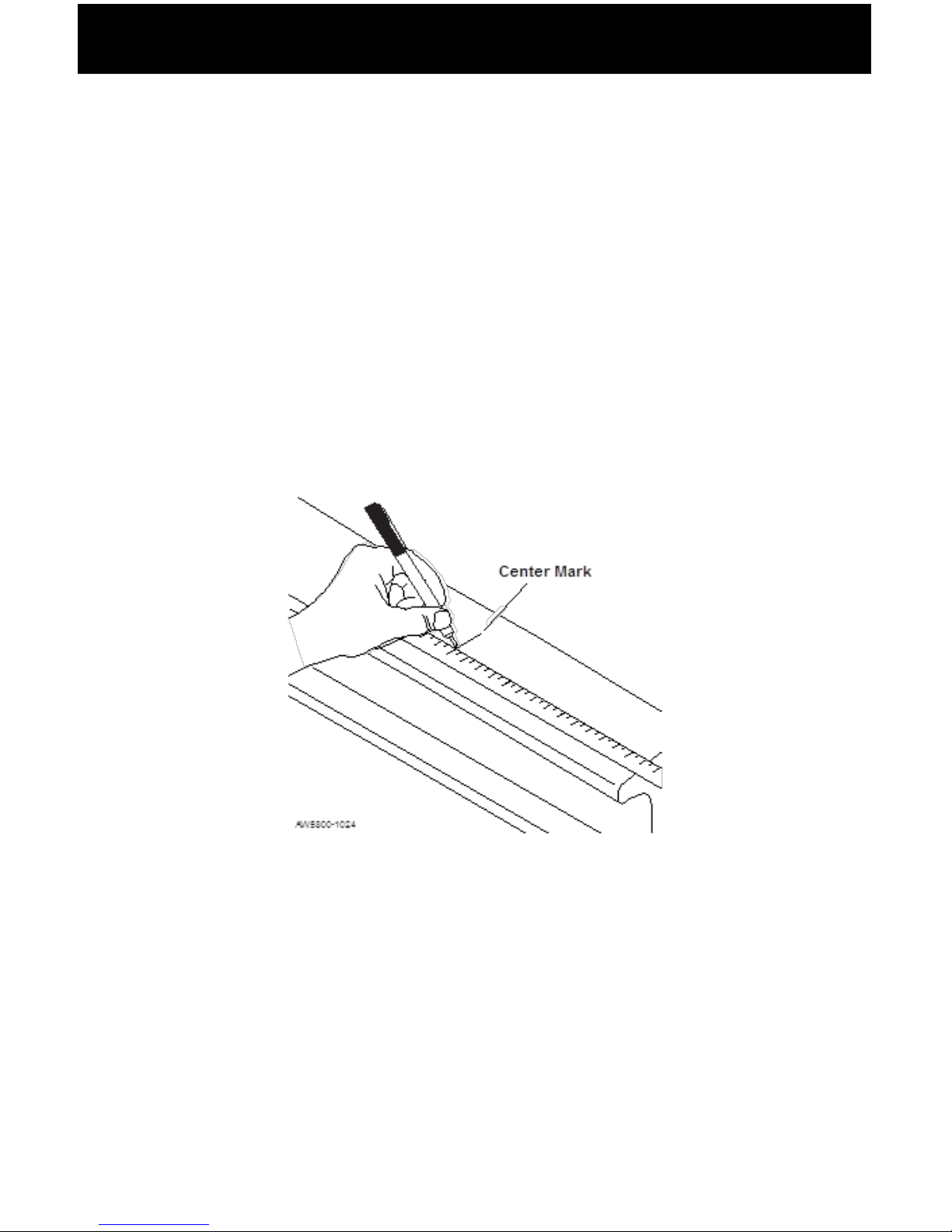
Preparing the Steer Axle Sensor Brackets...............................3
Welding the Bracket......................................................................6
Adding a Protective Spray Paint Coating..................................7
Installing the Drive Axle Sensor Bracket......................................8
Assembling the Bracket to the Jig.............................................8
J-Bracket Placement and Surface Preparation......................10
Welding the J-Bracket.................................................................12
Routing Cables...............................................................................13
Installing the ComLink and Display.............................................14
Preparing the Cab Display for Installation...............................14
Installing the Cab Display...........................................................14
Mounting the ComLink...............................................................15
ConnectingCables.........................................................................16
Power and Ground Table...........................................................16
Securing Cables and Reassembling the Dash......................16

3
Installing the Steer Axle Sensor...................................................17
Installing the Drive Axle Sensor...................................................19
Setting the A/D Values..................................................................20
Adjusting the A/D Readings......................................................21
Final Sensor Torque...................................................................22
Steer Axle Cover Installation........................................................23
Limited Warranty...........................................................................25
Procedure for Warranty Claims...................................................26
Notes...............................................................................................27

1
About LoadMaxx for Hendrickson
Suspensions
LoadMaxx is a weighing system for vehicles that works by using
that number into weight, which is displayed in the truck cab. Weight
information, including axle group, net, and gross vehicle weights, is
also displayed.
The LoadMaxx scale for vocational vehicles with Hendrickson
suspension includes a dash-mounted display, a ComLink
mounting hardware for the Hendrickson suspension.
Please see the User Guide, included with your scale kit, to calibrate
your scale after installation.
About Installation
Overview
There are three major components of the LoadMaxx scale that you
will install, listed as follows:
• Electronics: dash-mounted display, ComLink module,
power cables and sensor extension cables
•
only)
•

2
Tools Required
the steer and drive axles.
• Sander/grinder
• 40-grit medium sandpaper
• Chalk or permanent marker
• 22 MM combination wrench
• Torque wrench
• 22 MM socket and socket handle
• Enamel spray paint, any color
• Welder, MIG or ARC
• E7018 welding electrodes for ARC welders
• E70S-3 or E71T-1 welding wire for MIG welders
• C-clamps
• Tape measure
Note: The reusable Installation Jig (sold separately) is required for
this installation.
Optional Tools

3
Installing the Steer Axle Sensor
Bracket
Note: This section applies only to scales using the 5817
skip
this section and see the section on installing the drive axle sensor
(page 6).
Preparing the Steer Axle Sensor Brackets
1. Locate and mark the center of the steer axle.
2. Using chalk or a permanent marker, mark the top of the
total). Clean this area. If the axle is heavily caked with dirt
or grease, use a degreaser such as Brakleen to remove the
worst.
3. Using 40-grit medium sandpaper or a pneumatic grinder,
sand the 6-inch area until nothing remains but bare metal.
We recommend that you partially grind down the mold line as
well.
Marking the Center of the Steer Axle

4
4. Re-mark the center of the steer axle.
and that no axle paint is left under the pad. If there is any
paint at all that will be touching the brackets, sand until it has
been removed.
6. Once you have prepared the axle, place the bracket
rocking in any direction. If the bracket rocks, sand or grind off
Note: Make sure that the main body of the bracket does not touch
the axle. Only the feet of the bracket should touch the axle.
Sanding the Steer Axle

5
7. If the brackets have protective tape on them, remove the tape
from around the bottom of the bracket assembly.
Removing the Protective Plastic Strips
8. Clean the underside of the bracket assembly with one of the
supplied isopropyl alcohol pads.
Cleaning the Bottom of the Bracket Assembly

6
Welding the Bracket
Note: Air-Weigh takes no responsibility for damage or failure of the
steer axle due to improper welding.
1. Place the new bracket assembly at the center of the axle.
place. Make sure you leave the alignment tool in the bracket
assembly while welding.
2. Tack weld all 8 corners of the base.
Bracket Assembly Centered on Axle
Note: Do not operate the vehicle while the alignment tool is still in
place.
TACK WELD LOCATIONS

7
Adding a Protective Spray Paint Coating
To prevent steer axle corrosion, we recommend you spray paint
around the base of the bracket.
1. Using any enamel-based spray paint, paint around the base
of the bracket and over the welded section. Paint all bare
metal around the bracket completely.
2. Once the paint is dry, we recommend that you paint all
exposed metal a second time.
Spray Paint Coating
3. Fillet weld a full bead on the front and back edges of each
of the bracket, only the edges indicated below. Air-Weigh
recommends that you use equipment similar to Miller
Shopmaster 300 AC/DC; AMP/VOLT setting of 22; wire
speed of 3.5; and a welding argon gas mixture of 75/25. MIG
the same settings as the Miller Shopmaster noted above.

8
Installing the Drive Axle Sensor
Bracket
Assembling the Bracket to the Jig
Note: You must make sure that the frame rail will not hit the top of
frame stop and the suspension is at least a 1/2 inch more than the
distance from the top of the bracket to the frame rail above it.
1.
J-bracket and then through the jig.
2.
hex nut.
Assembling the J-Bracket to the Jig

9
Completing the J-Bracket Assembly
3. Make sure both alignment pins are touching the J-bracket.
4. Securely tighten the J-bracket to the jig assembly.
5. Repeat the above steps using a second J-Bracket. Ensure all
edges are parallel and at the same height.

10
J-Bracket Placement and Surface Preparation
1.
bar pin end on either the front or the back of the equalizing
beam. Put the J-bracket assembly against the spacer onto
the equalizing beam.
Hendrickson HAULMAXX
Hendrickson HN462/463
120-0079-XXX 120-0080-XXX

11
mark the area inside the two large holes of each J-bracket.
3. Remove the J-bracket assembly and set it aside.
4. Using a sander or grinder with 40-grit sandpaper, clean a
wide area around the marked areas until only bare metal is
visible.
5. Repeat steps 1-4 on opposite side of the suspension so you
have one bracket on the passenger’s side and one on the
driver’s side of your suspension.
Preparing Suspension Surface for Welding

12
Welding the J-Bracket
1. Using the appropriate spacer, place the J-bracket assembly
back on the walking beam.
2. Using two C-clamps, secure the bracket assembly to the
walking beam.
3. Using a MIG or ARC welder, tack-weld the two large holes
4. Then plug-weld the circumference of the two large holes in
the J-bracket assemblies only.
5. Once the welds are completely cooled, remove the clamps.
from the J-bracket assembly and remove the assembly jig.
Repeat with the second J-bracket on the opposite side of the
suspension and retain the nuts and bolts.
7. Use enamel spray paint and paint all welded and sanded
areas to prevent oxidization. Do not paint where sensor will
be installed.
Clamping the J-bracket Assembly to the Suspension

13
Routing Cables
1. Route the 20’ steer extension cable and the 40’ drive
extension cable along their respective axles and the frame,
sensor connections. If at all possible, route along an existing
wire harness. Be careful to avoid routing along pieces of the
frame that may move or cause wiring to rub.
2. Secure the cables loosely to the suspension using zip ties.
Note: Keep all cables a minimum of 12” from exhaust piping or
properly shield cables.

14
Installing the ComLink and Display
The Optional Universal Mounting Pod can be used for installations
where there is no space in the dash to mount the scale display.
Preparing the Cab Display for Installation
and its connections. A higher dash position provides better
visibility.
will mount the display.
Installing the Cab Display
the dash.
using 6 in-lbs. of torque. Do not over- tighten the mounting
Display Preparation and Installation

15
Mounting the ComLink
1. Select a location behind the dash for the ComLink module,
ensuring there is adequate access to the scale and the
electrical connections.
2. The ComLink module should be oriented with the connectors
facing downward and installed by either one of the following
methods, using the hardware provided:
Use zip ties through the holes in the ComLink module
mounting ears to secure it to any appropriate wire harness
behind the dash.
-OR -
attached using the 2-sided adhesive tape already in position
on the back of the ComLink module. Remove all dust, grease
pad. Remove one or both of the red strips from the back of
the ComLink module, exposing the adhesive tape. Place
hard enough to ensure adhesion. For best results, push the
ComLink module into place using 15 ft lbs of pressure,
being careful not to crack the case. Using this method will
Printer Installation Instructions for information on connecting the
printer to the ComLink.

16
Connecting Cables
The provided cables are used to connect the ComLink to the
vehicle’s electrical system, to the dash display unit, and, if desired,
to an alarm output.
Power and Ground Table
White Wire Vehicle Chassis Ground
Blue/Black Wire with In-
Line Fuse
12VDC or 24VDC Key
Hot Power
Gray Wire/Brown Wire Alarm output 1 and 2
vehicle power)
Black Wires Alarm ground Return 1
and 2
1. Connect the white wire to chassis ground.
“hot” side of the 12 VDC or 24 VDC key hot power source.
3. Connect the 10-pin plug of the power interface cable to the
ComLink module.
4. Connect both the 2-pin and the 4-pin plugs of the power
interface cable to the display.
5. When using an alarm, connect the alarm output wire and the
etc.).
Securing Cables and Reassembling the Dash
1. Connect the extension cable to the ComLink module in the
dash. Drive cables should be connected to Port A and the
steer cable should connect to Port B.
2. Coil and secure any excess wire using zip ties.
3. Tighten all zip ties and trim.
4. Reassemble the dash assembly after all sensors have been
Ensure all connections are tight.

17
Installing and Adjusting the Steer
Axle Sensor
1. Remove the alignment tool from the brackets. Retain the
nuts and bolts.
2. Insert the steer axle sensor with its cable extending toward
the side of the vehicle where the sensor extension cable has
faces up.
3. Align the steer axle sensor with the holes in the steer axle
bracket assembly.
4. Insert one bolt through the bracket hole on the sensor end
with the engraved lettering on it so that the bolthead is
secured in the manufactured bolthead holder. Place a washer
and a nut at the end of the bolt and hand-tighten the nut. Add
Loctite, or other threadlocker adhesive, to the bolts to prevent
loosening and corrosion.
Inserting the Sensor Into the Bracket
Table of contents
Other Air Weigh Accessories manuals